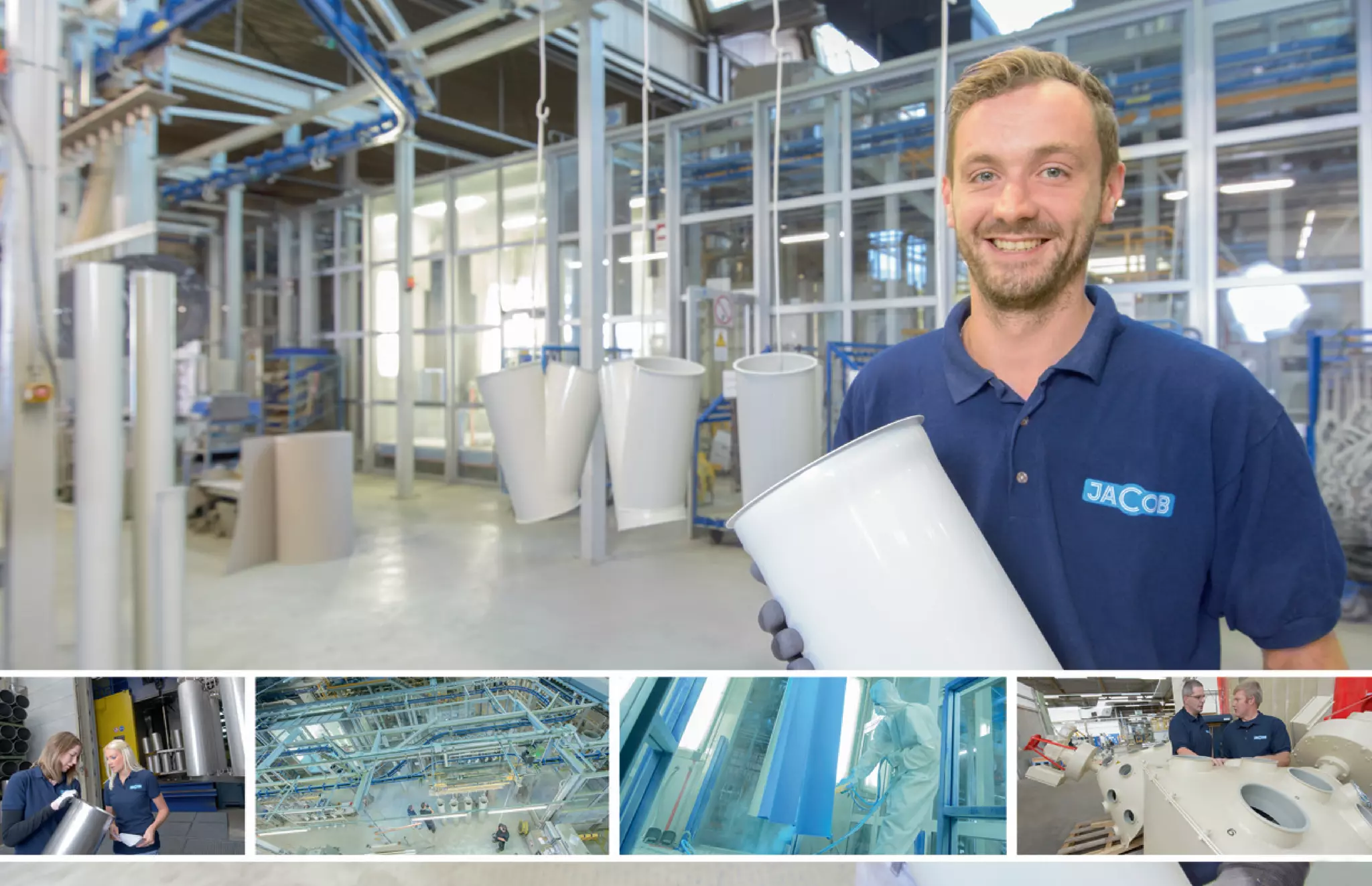
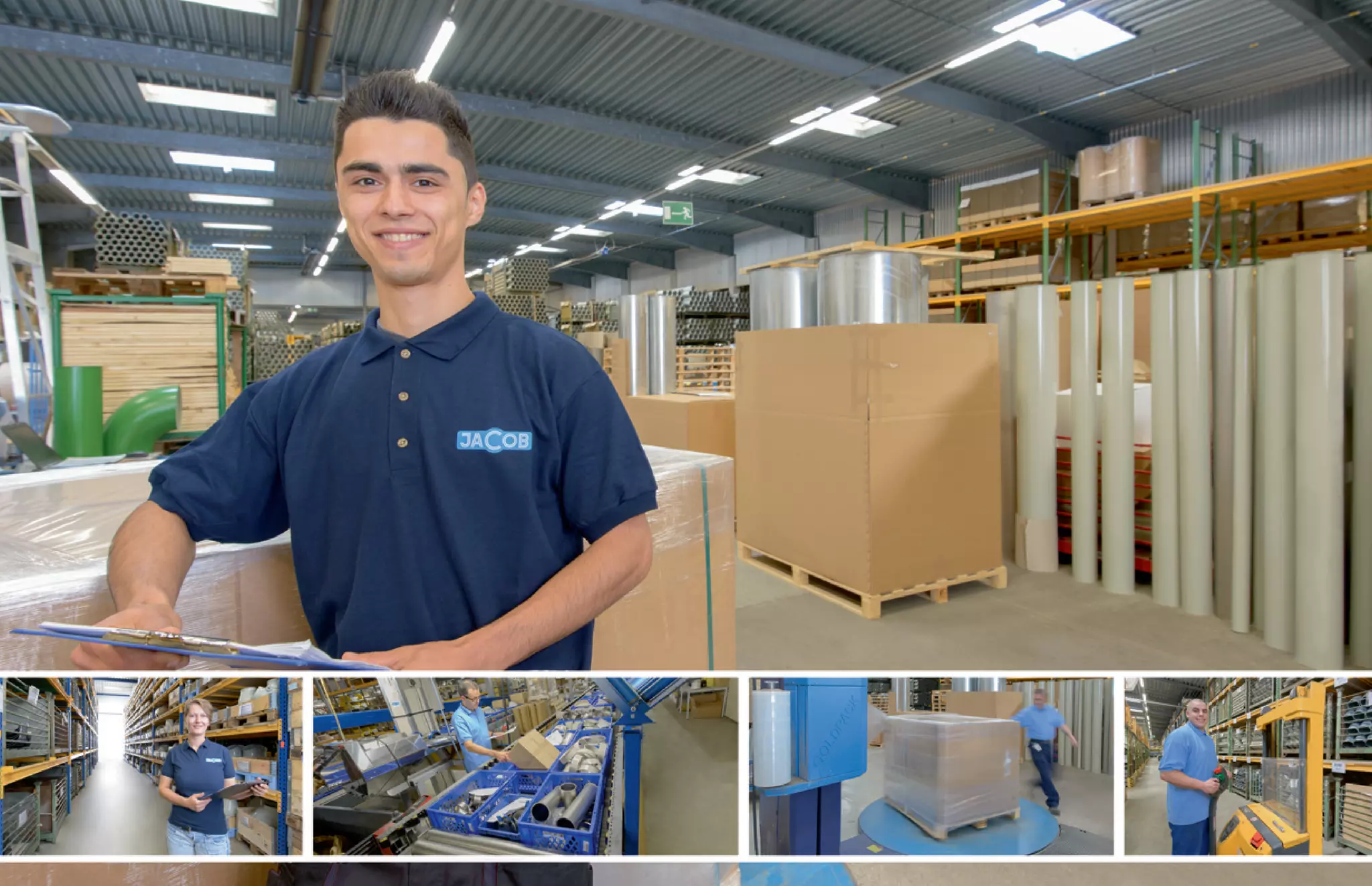
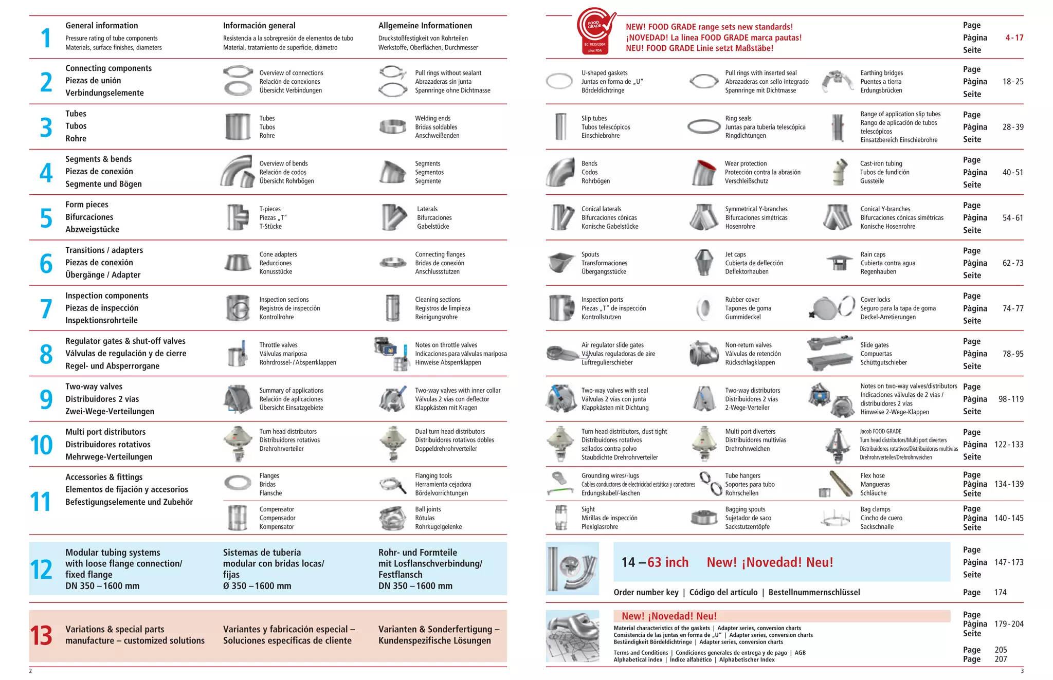
Das Dokument beschreibt ein Produktkatalog für modulare Rohrsysteme, die nach dem Baukastenprinzip gefertigt werden. Es hebt die Qualität, Verfügbarkeit und die breite Anwendung der Rohrsysteme in verschiedenen Industrien hervor, einschließlich Lebensmittel, Chemie und Pharma. Die Jacob-Gruppe, gegründet 1924, ist Marktführer in Europa und bietet über 5.000 verschiedene Produkte mit kurzer Lieferzeit an.
![16 17
1
1
Normalstahl: Werkstoff DC 04 (ST 1403)
Werkstoff DC 01 (ST 1203)
Pulverbeschichtung:
Gepulvert innen und außen (DN 60 – 630 mm).
Die Pulverbeschichtung ist elektrostatisch ableitfähig.
Alle verwendeten Rohstoffe unserer Standardpulver
beschichtung in Anlehnung an Farbton RAL 7032
(kieselgrau) erfüllen die FDA-Anforderungen für den
direkten Kontakt mit Lebensmitteln (z. B. Bestimmung
21 CFR175.300 „Resinious and polymeric coatings“)
Schichtstärke außen: Pulvergrundierung mit einer
Auftragsstärke von durchschnittlich 55 μm.
Temperaturbeständigkeit: Von -60 °C bis +120 °C
nahezu stabile Pulverlackeigenschaften.
Schichtdicke innen: optisch deckend. Die Innen
beschichtung ist grundsätzlich nur erforderlich,
um einen temporären Korrosionsschutz unter Lager-
und Transportbedingungen bis zum Einbau der Produkte
zu erreichen.
Spritzgrundierung:
Grundierung innen und außen, in Anlehnung an Farbton
RAL 7032 (kieselgrau).
Grundierte Oberflächenqualität ist im Katalog gekenn
zeichnet. Durchmesser > 630 mm sind im Standard
grundiert. Auf Anfrage auch pulverbeschichtet.
Rohrteile innen ungrundiert nach Aufwand möglich.
Endlackierung Rohr- und Formteile
(RAL-Farbskala, außen, auf Nachfrage)
Mehr als 3.000 Farb- und Effektvarianten, Sonderfarben
sowie Strukturlacke bis zum Durchmesserbereich
630 mm auf Anfrage gepulvert lieferbar.
Acero normal: material DC 04 (ST 1403)
y DC 01 (ST 1203)
Recubrimiento de polvo:
Pulverizado en la parte interior y exterior (DN 60 – 630
mm). El recubrimiento de polvo tiene capacidad de deri
vación electrostática. Todas las materias primas utiliza
das en nuestro recubrimiento de polvo estándar con la
tonalidad de color RAL 7032 (gris guijarro) satisfacen los
requisitos FDA para el contacto directo con alimentos (p.
ej. disposición 21 CFR175.300 „Resinious and polymeric
coatings“ – recubrimientos resinosos y poliméricos).
Grosor de capa exterior: imprimación protectora contra
polvo con un grosor de aplicación de 55 μm como valor
medio. Resistencia a la temperatura: de -60 a +120 °C,
propiedades de pintura en polvo prácticamente estables.
Grosor de capa interior: cubre visualmente. Por regla
general, el recubrimiento interior sólo es necesario para
lograr una protección anticorrosiva temporal en condi
ciones de almacenamiento y transporte hasta el montaje
de los productos.
Imprimación pulverizada:
Imprimación interior y exterior, RAL 7032 (gris guijarro).
La calidad de la superficie imprimada está marcada en el
catálogo. Los diámetros a partir de 630 mm tienen una
imprimación en la versión estándar. Bajo demanda,
también pueden recubrirse de polvo. También pueden
suministrarse piezas de tubo sin imprimación en función
del gasto.
Barnizado final de piezas de tubo y molde
(escala de colores RAL, exterior, bajo demanda)
Bajo demanda pueden suministrarse más de 3.000
variantes de colores y efectos, colores especiales y
barnices estructurales pulverizados para diámetros de
hasta 630 mm.
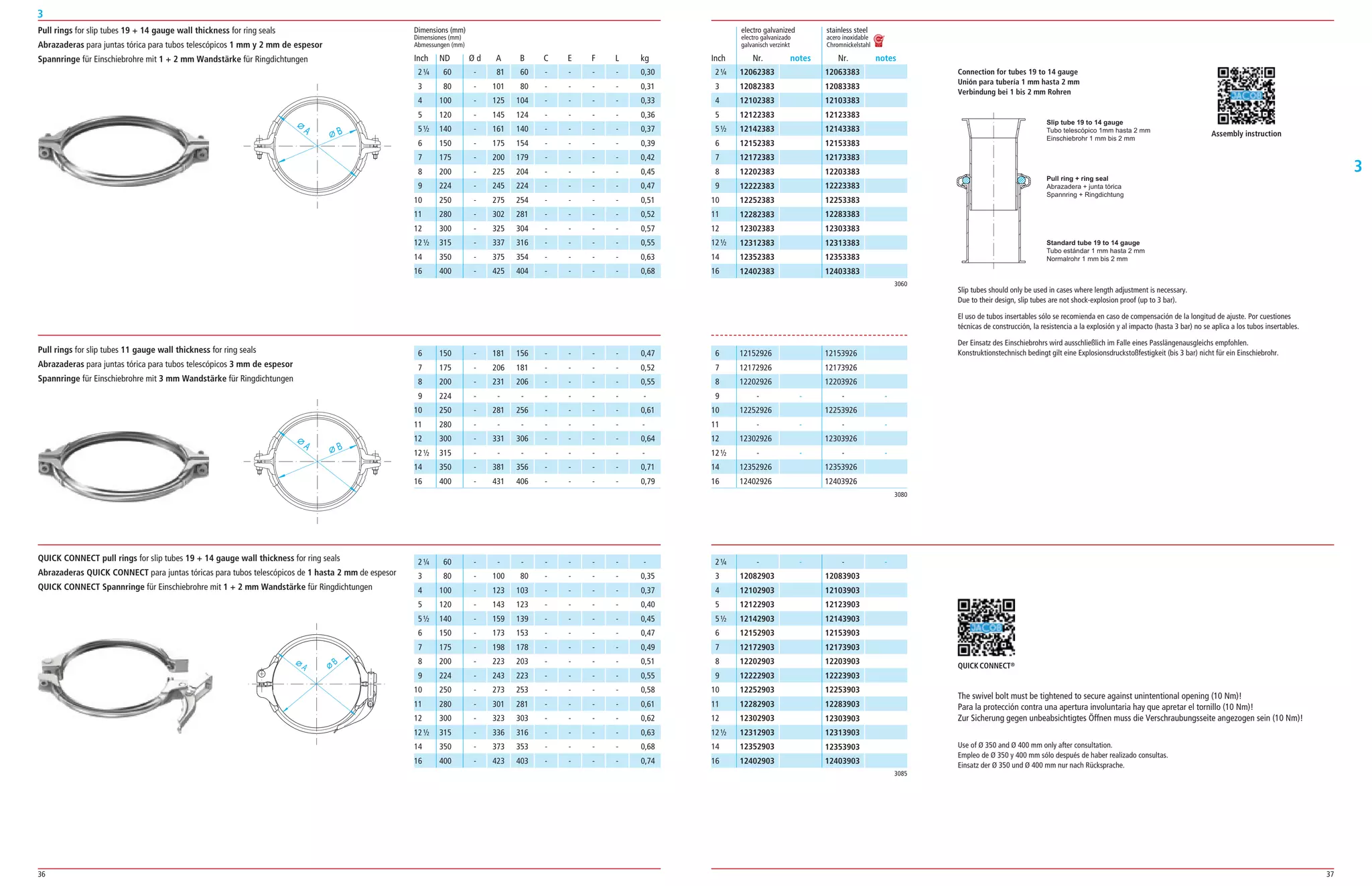
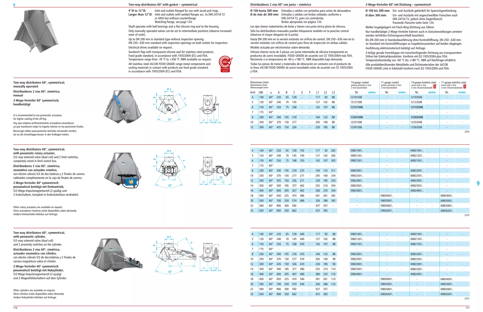
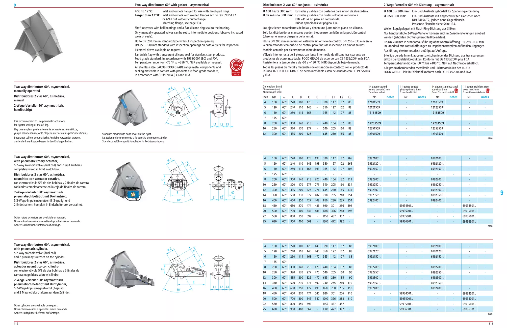
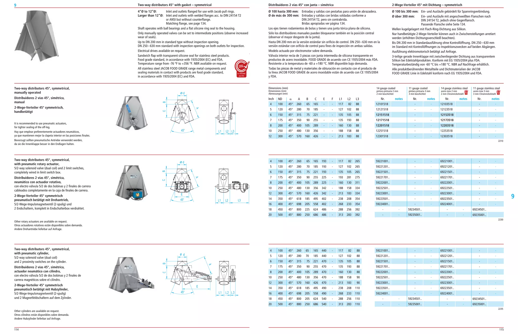
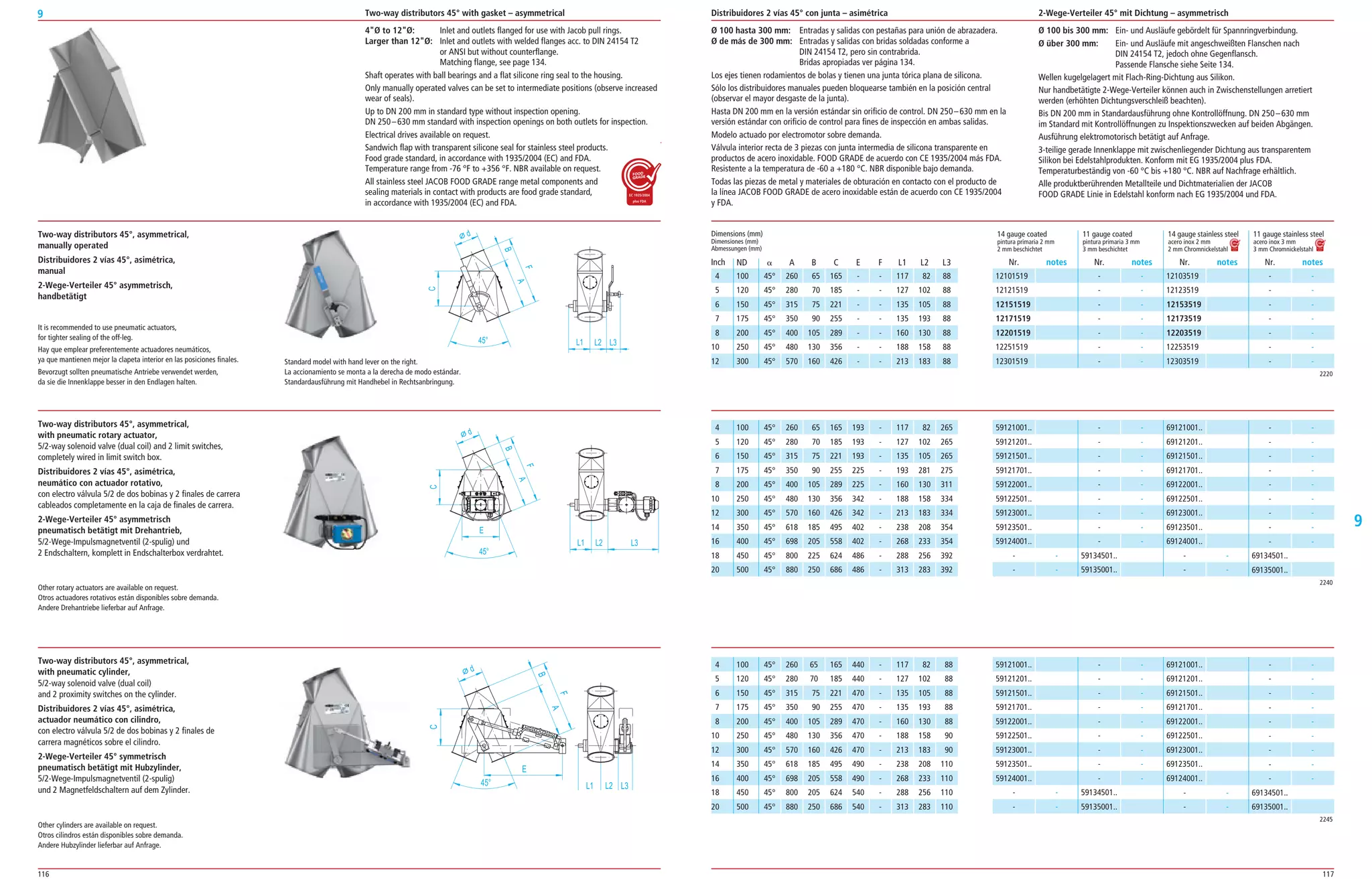
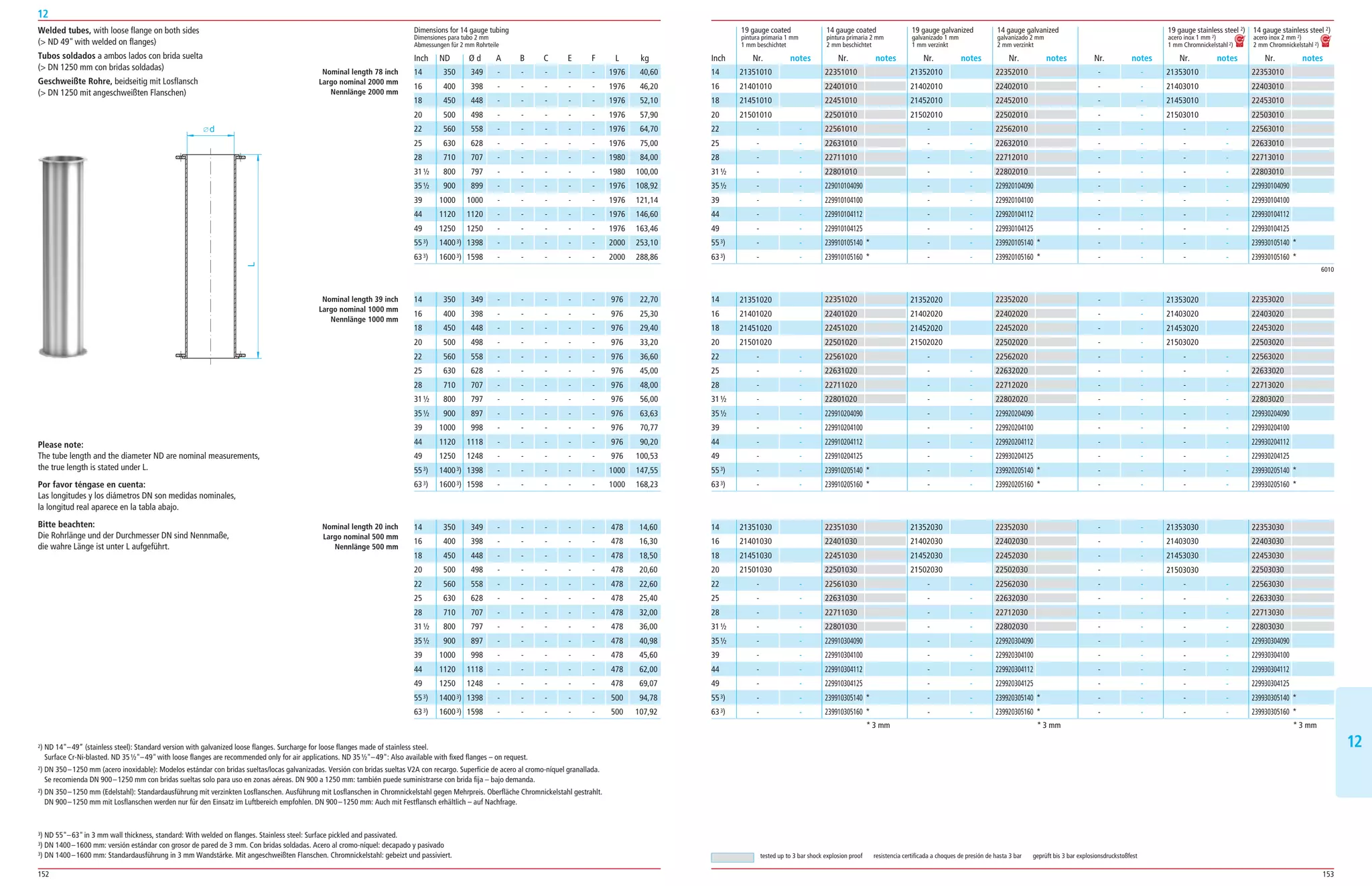
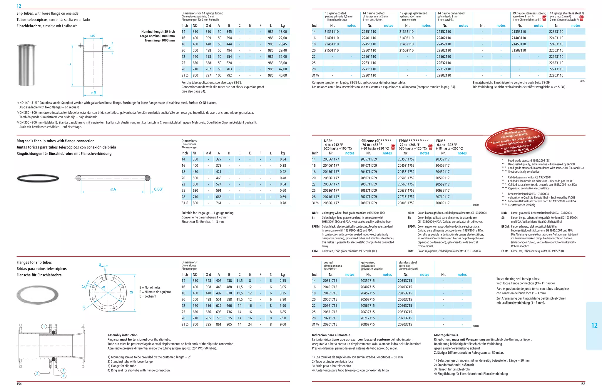
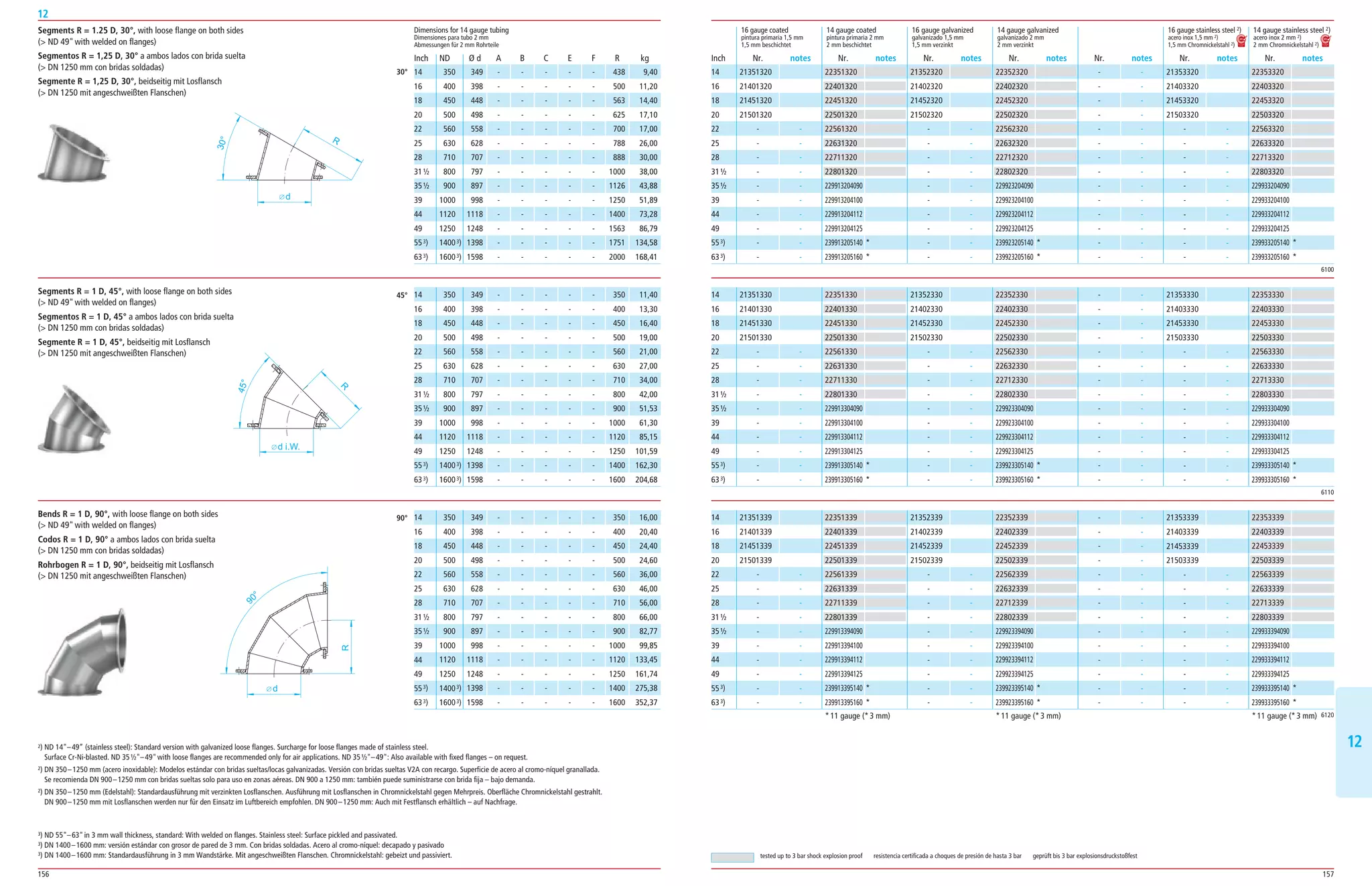
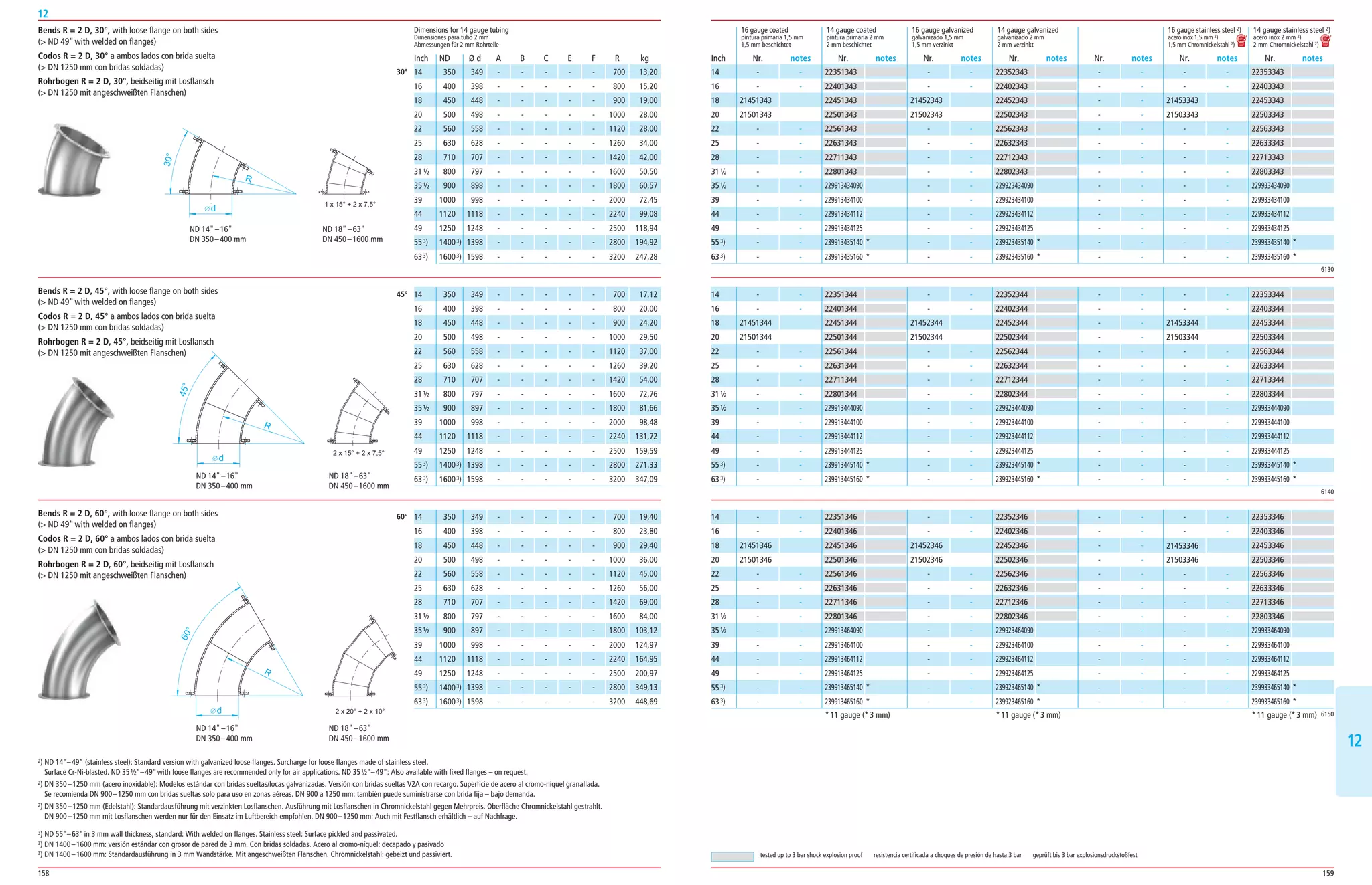
Flange for pull ring connection
Rebordeado para conexiones con abrazadera
Bördelrand für Spannringverbindung
Inside diameter (d)
of the tubing in relation to the
nominal diameter (DN).
Diámetro interior (d)
de las piezas referido al
diámetro nominal (DN).
Innendurchmesser (d)
der Rohrteile bezogen auf den
Nenndurchmesser (ND).
60 mm - 57 - -
80 mm 78 77 76 -
100 mm 100 100 99 -
120 mm 120 120 119 118
140 mm 136 136 135 -
150 mm 150 150 149 148
175 mm 175 175 174 173
200 mm 200 200 199 198
224 mm 220 220 219 -
250 mm 250 250 249 248
280 mm 272 277 276 274
300 mm 315 315 314 313
315 mm 313 312 311 309
350 mm 350 350 349 348
400 mm 400 399 398 396
450 mm 450 449 448 446
500 mm 500 499 498 496
560 mm - 559 558 556
630 mm - 629 628 626
ND s = 1mm s = 1,5mm s = 2mm s = 3mm
Werkstoffe
MaterialesMaterials
Tolerancias:
Diámetro de tubo y redondez – DIN EN 10296-1.
Medidas de longitudes y ángulos – DIN ISO 2768-1 –
clase de tolerancia V.
Excepción: segmentos y empalmes con tolerancia de
ángulo de inclinación ±1°. El grosor de pared puede
variar en piezas embutidas o rectificadas.
Conexiones:
Siempre que no se evidencie lo contrario, las piezas de
tubo están rebordeadas 6 mm en los extremos para
uniones de abrazaderas.
Los diámetros de 60, 80, 140 y 224 mm apenas se
utilizan en el ámbito de productos a granel, y algunos
grosores de pared y piezas de tubo y molde, como p. ej.
válvulas de 2 vías, no se hallan disponibles con esos
diámetros.
Grosor de capa total (incluida imprimación):
80 μm como mín. Bajo demanda, capacidad de
derivación electrostática con recargo.
Bajo demanda pueden suministrarse pinturas de
pulverización alternativas.
Galvanización en caliente según DIN EN ISO 1461:
Los grosores promedio de las capas (valores mínimos)
dependen
del grosor de material del acero:
< 1,5 mm: 45 μm, ≥ 1,5 a ≤ 3 mm: 55 μm,
≥ 3 a ≤ 6 mm: 70 μm.
Resistente a la temperatura hasta 200 °C.
Galvanización según DIN 50961.
Grosor de capa: aprox. 10 μm.
Resistente a la temperatura hasta 120 °C.
Acero al cromo-níquel: material 1.4301,
(X5CrNi18-10), AISI 304 (V2A) (1.4307 [X2CrNi18-9],
AISI 304L, V2A). Superficie Cr-Ni-granallada.
Resistente a la temperatura hasta 300 °C.
También de material 1.4571(X6CrNiMoTi17-12-2),
AISI 316Ti (VA4) (1.4404 [X2CrNiMoTi17-12-2],
AISI 316L, V4A). La superficie también puede suminis
trarse decapada y pasivada. Precios V4A bajo demanda.
Conformidad CE 1935/2004 más FDA
Los productos de acero inoxidable JACOB fabricados con
los materiales 1.4301, 1.4571 o equiparables satisfacen
los criterios descritos en las ”EU-Guidelines on metals,
alloys used as food contact materials (13.02.2002)“
(directrices UE sobre metales y aleaciones utilizadas
como materiales en contacto con alimentos) del Consejo
Europeo. Los mismos son adecuados y están permitidos
para el contacto con alimentos en función del grado de
carga corrosiva.
Gesamtschichtstärke (einschließlich Grundierung):
zirka 80 μm.
Elektrostatische Ableitfähigkeit aufpreispflichtig auf
Nachfrage.
Alternative Spritzlackierung auf Nachfrage erhältlich.
Feuerverzinkung nach DIN EN ISO 1461:
Durchschnittliche Schichtdicken (Mindestwerte) sind von
der Materialdicke des Stahls abhängig:
< 1,5 mm: 45 μm, ≥ 1,5 mm bis ≤ 3 mm: 55 μm,
> 3mm bis ≤ 6 mm: 70 μm.
Temperaturbeständig bis 200 °C.
Verzinkung nach DIN 50961. Schichtstärke ca. 10 μm.
Temperaturbeständig bis 120 °C.
Chromnickelstahl: Werkstoff 1.4301 (X5CrNi18-10),
AISI 304 (V2A) (1.4307 [X2CrNi18-9], AISI 304L, V2A)
Oberfläche Cr-Ni-gestrahlt.
Temperaturbeständig bis 300 °C.
Auch aus Werkstoff 1.4571(X6CrNiMoTi17-12-2),
AISI 316Ti (VA4) (1.4404 [X2CrNiMoTi17-12-2],
AISI 316L, V4A). Oberfläche gebeizt und passiviert
lieferbar. Preise V4A auf Anfrage.
Konformität EC 1935/2004 plus FDA
JACOB Edelstahlprodukte aus den Werkstoffen 1.4301,
1.4571 oder vergleichbare entsprechen den Kriterien,
die in den „EU-Guidelines on metals, alloys used as food
contact materials (13.02.2002)“ des Europarates
beschrieben sind. Sie sind je nach Grad der korrosiven
Belastung für den Kontakt mit Lebensmittel geeignet
und zugelassen.
Mild steel: material DC 04 (ST 1403)
material DC 01 (ST 1203)
Powder coating:
Powder coated inside and outside 2 ¼" – 25" (DN
60 – 630 mm). The powder coating is electrostatically
conductive. All of the raw materials used in our
standard powder coating, color pebble grey, similar to
RAL 7032, comply with the FDA requirements for
direct contact with food (e.g. regulation 21 CFR175.300
“Resinous and polymeric coatings”).
Coating thickness on the outside: Powder coating as
primer with an average ayer thickness of 55 μm.
Temperature resistance: Powder coating properties are
practically stable between -76 °F to 248 °F (-60 °C to
+120 °C).
Layer thickness on the inside: The surface is optically
covered. The coating on the inside is only necessary to
provide temporary corrosion protection in storage and
transport conditions until the products have been instal
led.
Priming (Spray painted):
Inner and outer priming, color pebble grey,
similar to RAL 7032.
Primed surface finish is identified in the catalog.
Diameters of 25 ( 630 mm)
are primed in the standard quality. Powder coating also
available on request. Tube components with inside
uncoated are available at cost.
Final coating for modular tubing systems
(RAL color chart, external, on request):
More than 3 000 color and effect variations; special
colors and structured coatings up to 25 (630 mm)
diameter available powder coated, on request.
Total thickness of coating (including primer):
Approximately 80 μm.
Electrical conductivity on request, at a surcharge.
Alternatively spray painted, on request.
Hot-Dip Galvanized acc. to DIN EN ISO 1461:
Average coating thickness (minimum value) depends on
the thickness of the steel:
16 gauge (1.5 mm): 45 μm, ≥ 16 gauge (≥ 1.5 mm) to
≤ 11 gauge (≤ 3 mm): 55 μm, 11 gauge ( 3 mm) to
≤ 6 mm: 70 μm.
Withstand temperature up to 392 °F (200 °C).
Galvanic method according to DIN 50961.
Coating thickness approx. 10 μm.
Withstand temperature up to 248 °F (120 °C).
Stainless steel: material 1.4301 (X5CrNi18-10),
AISI 304 (V2A) (1.4307 [X2CrNi18-9], AISI 304L, V2A)
surface Cr-Ni-blasted.
Temperature resistance up to 572 °F (300 °C).
As well as material 1.4571(X6CrNiMoTi17-12-2),
AISI 316Ti (VA4) (1.4404 [X2CrNiMoTi17-12-2],
AISI 316L, V4A). Available pickled and passivated.
Prices V4A on request.
Compliance 1935/2004 (EC) and FDA
JACOB’s stainless steel products made of 1.4301, 1.4571
or comparable grade steel comply with the criteria laid
down in the “EU guidelines on metals and alloys used as
food contact materials” (13.02.2002) issued by the
Council of Europe. They are suitable and approved for
use in contact with food, depending on the corrosiveness
of the medium.
Toleranzen:
Rohrdurchmesser und Rundheit – DIN EN 10296-1.
Längen- und Winkelmaße – DIN ISO 2768-1 –
Toleranzklasse V.
Ausnahme: Segmente und Übergangsstücke mit
Neigung, Winkeltoleranz ±1°. Bei gezogenen oder ge
schliffenen Teilen kann sich die Wandstärke verändern.
Anschlüsse:
Sofern nicht anders ersichtlich, sind die Rohrteile an den
Enden 6 mm gebördelt für Spannringverbindungen.
Die Durchmesser 60, 80, 140, und 224 mm werden kaum
im Schüttgutbereich eingesetzt, einige Wandstärken,
Rohr und Formteile, wie z. B. 2-Wege-Klappen sind in
diesen Durchmessern nicht lieferbar.
Tolerances:
Tube diameter and roundness – DIN EN 10296-1.
Lengths and angles – DIN ISO 2768-1 –
tolerance class V.
Exclusions: segments and spouts with inclination, angle
tolerance ±1°. The wall thickness can be amended for
specially drawn or cut components.
Connections:
Unless otherwise mentioned, the tube components have
6 mm flanged ends for pull ring connections.
Diameters 60, 80, 140, and 224 mm are rarely used
in areas handling bulk goods, certain wall thicknesses,
tube segments and components, such as two-way
valves, are not available in these diameters.
Inch
2 ¼
3
4
5
5 ½
6
7
8
9
10
11
12
12 ½
14
16
18
20
22
25](https://image.slidesharecdn.com/55fefb7c-a7cc-4008-a3e8-585e9ac72d72-150611141718-lva1-app6892/75/Jacob-Tubing-Product-Catalog-10-2048.jpg)