Downloaden Sie, um offline zu lesen


![CAVEX®
1 - 2
Legende / Erläuterungen Legend / Explanations
ED = Einschaltdauer in %
(z.B. ED = 80% je Stunde)
ED = Operating cycle per hour in %
(e.g. ED = 80% / h)
f1 ... f6 = Faktoren siehe Seite 1 - 3 f1 ... f6 = For factors, see page 1 - 3
f7 = Faktor aus Leistungstabellen f7 = For factor, see rating tables
i = Übersetzung = n1 / n2 i = Transmission ratio = n1 / n2
n1 = Antriebsdrehzahl [min-1
] n1 = Input speed [min-1
]
n2 = Abtriebsdrehzahl [min-1
] n2 = Output speed [min-1
]
P1N = Nenn-Antriebsleistung [kW] P1N = Nominal input power rating [kW]
P2 = Leistung der Arbeitsmaschine [kW] P2 = Power rating of driven machine [kW]
T2 = Abtriebsdrehmoment (Nm)
T2 = 9550 x P2 / n2
T2 = Output torque (Nm)
T2 = 9550 x P2 / n2
T2A = Betriebsspitzen-, Anfahr- oder Bremsmoment [Nm] T2A = Peak operating-, starting- or braking torque [Nm]
T2max = Kurzzeitig zulässiges maximales Drehmoment [Nm]
beim Anfahren
T2max = Briefly permissible maximum torque [Nm] when start
T2max* = Kurzzeitig zulässiges maximales Drehmoment bei
der in den Tabellen angegebenen niedrigsten
Drehzahl n1
T2max* = Briefly permissible maximum torque for the lowest
speed n1 indicated in the tables
Größenbestimmung Selection of size
Nach einer Vorabauswahl des Getriebes, bei der
T2N ≥ 1,2 x T2 sein soll, müssen folgende Bedingungen erfüllt
sein:
After a first selection of the gear unit where T2N should
be ≥ 1,2xT2 , the following conditions should be fulfilled:
I) T2N ≥ T2 x f1 x f2 x f3 mechanisches Grenzdrehmoment / mechanical limit torque
II) T2N ≥ T2 x f3 x f4 x f5 x f7 thermisches Grenzdrehmoment / thermal limit torque
III) T2max ≥ T2A x f2 x f3 mechanisches Anfahrmoment / mechanical starting torque
IV) T2max* ≥ T2A x f2 x f6 Zahngrenzbelastung / limit tooth load
Sind die Bedingungen reichlich erfüllt, kann ein kleineres Ge-
triebe versucht werden.
Sind die Bedingungen nicht erfüllt, muß ein größeres Getriebe
gewählt werden.
If the conditions are generously fulfilled one can try to select a
smaller gear unit.
If the conditions are not fulfilled a larger gear unit has to be
selected.
Zusätzliche Hinweise Additional notes
Bei festliegender Drehrichtungszuordnung zwischen An- und
Abtriebswelle wird evtl. linkssteigende Verzahnung erforder-
lich.
If the direction of rotation for input and output shaft has been
definitely decided, LH gear teeth might possibly become ne-
cessary.
Bei Anläufen unter Last ist zur ausreichenden Bemessung
des Antriebsmotors der Anlaufwirkungsgrad zu berücksichti-
gen, siehe Seite 1 - 24.
For starts under load, the starting efficiency has to be taken
into account for a sufficient dimensioning of the prime mover,
refer to page 1 - 24.
Bei vorgesehenen antriebsseitigen Bremsungen ist das zuläs-
sige Bremsmoment zu berücksichtigen, siehe Seite 1 - 25.
If braking on the input side is intended, the permissible braking
torque has to be taken into account, refer to page 1 - 25.
Bei Forderungen nach Selbsthemmung oder Selbstbremsung
siehe Seite 1 - 25.
If automatic locking or automatic braking is required, refer to
page 1 - 25.
Etwa vom Getriebe aufzunehmende äußere Kräfte sind zu
überprüfen, siehe Seite 1 - 14.
Possible external forces to be taken up by the gear unit are to
be checked, refer to page 1 - 14.
Bei der Größenbestimmung werden durch die Bedingung II
thermische Einflüsse berücksichtigt, wobei eine Schmierstoff-
temperatur von +100°C zugrunde liegt.
When selecting the size, thermal influences are taken into
consideration with condition II based on a lubricant tempera-
ture of +100°C.
Bei Umgebungstemperaturen unter -10°C oder über +50°C ist
Rücksprache erforderlich.
For ambient temperatures below -10°C or above +50°C, plea-
se refer to us.](https://image.slidesharecdn.com/flendercavex-170315053907/85/CAVEX-Flender-Siemens-7-320.jpg)
![CAVEX®
1 - 3
Betriebsfaktoren Service Factors
f1 für die Betriebsdauer und Belastungsart f1 for daily operating periods and load classifications
Tägliche Laufzeit [Std]
Daily operating hours [hrs]
1/2 im Aussetzbetrieb
1/2 intermittent operation
1/2 im Aussetzbetrieb
1/2 intermittent operation
über 2 bis 10
above 2 up to 10
über 10 bis 24
above 10 up to 24
Belastungskennwert G
Load classification symbol U
0,8 0,9 1 1,2
Belastungskennwert M
Load classification symbol M
0,9 1 1,2 1,4
Belastungskennwert S
Load classification symbol H
1 1,2 1,4 1,6
f2 für Anläufe, Spitzenmomente, Bremsungen f2 for starts, peak torques, braking
Häufigkeit je Stunde
Frequency per hour
bis 10
up to 10
> 10 - 60 > 60 - 240 > 240 - 600
f2 1 1,1 1,2 1,3
f3 für Schmierung mit Mineralölen (bei synth. Ölen ist f3 = 1) f3 for lubrication with mineral oils (for synthetic oils f3 = 1)
Getriebegröße
Gear unit size
63 - 100 120 - 250 280 - 450 500 - 630
f3 1,2 1,25 1,3 1,35
f4 für Einschaltdauer je Stunde (ED) f4 for operating cycle per hour (ED)
ED [%] 100 80 60 40 20
f4 1 0,94 0,86 0,74 0,56
f5 für Umgebungstemperatur (tu) f5 for ambient temperature (tu)
tu [°C] bis 10
up to 10
20 30 40 50
n1 [min-1
] f5
- 300 0,9 1 1,14 1,33 1,60
> 300 - 1500 0,9 1 1,17 1,42 1,75
> 1500 0,9 1 1,20 1,50 1,90
f6 für Lastrichtung f6 for direction of load
f6
1 bei gleichbleibender Lastrichtung / for constant direction of load
1,2 bei wechselnder Lastrichtung / for alternating direction of load](https://image.slidesharecdn.com/flendercavex-170315053907/85/CAVEX-Flender-Siemens-8-320.jpg)


![CAVEX®
1 - 9
Erforderliche Angaben für eine Getriebeauswahl Necessary details for the choise of the gear
Checkliste Checklist
An
To
Flender Tübingen
Bahnhofstr. 40 - 44
D-72072 Tübingen
Tel.: +49 (0)7071/707-0 Telefax: +49 (0)7071/707-400
Fax:
Von
From
Flender / Tel.: Telefax.:
Fax:
Datum:
Date:
Name:
Projekt:
Project
Stückzahl:
No. of pieces:
Firma:
Company
Ansprechpartner:
Contact person:
Tel.:
E-mail:
Getriebedaten Gear unit data
Bauart Unit type
Größe Size
Abtriebsmoment T2 Output torque T2 [Nm]
max. Abtriebsmoment T2max max. Output torque T2max [Nm]
geplante Antriebsleistung (P1) planned driving power (P1) [kW]
Antriebsdrehzahl n1 Input speed [min-1]
Übersetzung i Transmission ratio
Einbaulage Mounting position
Abtriebswelle auf Seite Output shaft on side
Flansch auf Seite Flange on side
Drehmomentstütze auf Seite / Stellung Torque arm on side / in position
mit / ohne Endscheibe with or without end plate
Antriebswelle in Stellung Input shaft on side
Umgebungstemperatur TU 1) Ambient temperaures TU 1) [°C]
Einschaltdauer ED Operating cycle ED [h/day]
Verbindung Getriebe-Motor Mounting of IEC motor at the gear unit
Motor-Baugröße Size of the motor
Kupplungs-Baugröße Size of the coupling
Art der Kupplung Type of coupling
Motordaten Electric motor data
Größe Size
Bauform Mounting position
Schutzart Type of protection
Nennleistung Nominal input power rating [kW]
Drehzahl Rated motor speed [min-1]
Nennspannung Rated motor voltage [V]
Frequenz Rated motor frequency [s-1
]
Zusatzausstattungen Additional features
Beschreibung der Belastungs- und Umgebungsverhält-
nisse / zusätzliche Informationen
Additional data / information describtion of proced to be
driven / additional informations
1) Bei Umgebungstemperatur unter -10°C oder über +50°C
ist Rücksprache erforderlich.
1) For ambient temperature below -10°C or above +50°C
please contact us.](https://image.slidesharecdn.com/flendercavex-170315053907/85/CAVEX-Flender-Siemens-14-320.jpg)


![CAVEX®
1 - 26
Massenträgheitsmomente J1 [kgm2] Mass moments of interia J1 [kgm2]
Übersetzung
Ratio
Getriebegröße / Gear unit size
63 80 100 120 140 160 180 200 225
Einstufige CAVEX®
-Schneckengetriebe / Single stage CAVEX®
worm gear units
5 - 6 0,00015 0,00052 0,0016 0,0034 0,0076 0,014 0,024 0,037 0,061
6 - 8 0,00013 0,00041 0,0013 0,0027 0,0059 0,011 0,019 0,029 0,048
8 - 10 0,00011 0,00035 0,0011 0,0023 0,0049 0,009 0,016 0,024 0,040
10 - 15 0,00010 0,00030 0,0010 0,0020 0,0043 0,008 0,014 0,020 0,033
15 - 30 0,00009 0,00026 0,0009 0,0017 0,0036 0,007 0,012 0,018 0,028
30 - 67 0,00008 0,00024 0,0008 0,0016 0,0033 0,006 0,011 0,016 0,026
CAVEX®-Stirnradschneckengetriebe / CAVEX® helical worm gear units
20 - 25 0,00011 0,00017 0,00050 0,00082 0,0021 0,0030 0,0063 0,0086 0,017
25 - 30 0,00009 0,00012 0,00038 0,00057 0,0015 0,0021 0,0045 0,0057 0,012
30 - 38 0,00010 0,00015 0,00051 0,00071 0,0019 0,0027 0,0064 0,0074 0,015
38 - 46 0,00009 0,00012 0,00047 0,00052 0,0014 0,0019 0,0043 0,0051 0,011
46 - 60 0,00007 0,00009 0,00027 0,00036 0,0010 0,0012 0,0030 0,0036 0,008
60 - 73 0,00010 0,00014 0,00049 0,00070 0,0018 0,0025 0,0056 0,0070 0,015
73 - 90 0,00009 0,00011 0,00035 0,00050 0,0014 0,0018 0,0041 0,0048 0,011
90 - 112 0,00007 0,00009 0,00027 0,00036 0,0010 0,0012 0,0029 0,0035 0,008
112 - 140 0,00005 0,00007 0,00022 0,00026 0,0007 0,0009 0,0021 0,0024 0,006
140 - 335 0,00004 0,00006 0,00015 0,00018 0,0005 0,0006 0,0015 0,0017 0,004
CAVEX®
-Doppelschneckengetriebe / CAVEX®
tandem worm gear units
170 - 580 - - 0,00010 0,00010 0,00031 0,00033 0,0010 0,0011 0,0020
580 - 4300 - - 0,00008 0,00009 0,00025 0,00026 0,0008 0,0008 0,0016
Übersetzung
Ratio
Getriebegröße / Gear unit size
250 280 315 355 400 450 500 560 630
Einstufige CAVEX®
-Schneckengetriebe / Single stage CAVEX®
worm gear units
5 - 7 0,10 0,14 0,23 0,38 0,63 1,07 1,58 2,59 4,08
7 - 9 0,08 0,11 0,18 0,30 0,49 0,81 1,20 1,85 2,94
9 - 11,5 0,06 0,09 0,15 0,24 0,39 0,67 0,95 1,45 2,23
11,5 - 18 0,06 0,08 0,13 0,20 0,32 0,59 0,81 1,21 1,75
18 - 33 0,05 0,07 0,11 0,17 0,25 0,49 0,67 0,95 1,32
33 - 75 0,04 0,06 0,10 0,15 0,22 0,43 0,57 0,80 1,07
CAVEX®
-Stirnradschneckengetriebe / CAVEX®
helical worm gear units
22 - 28 0,023 0,050 0,062 0,14 0,17 0,46 0,52 1,27 1,40
28 - 35 0,016 0,038 0,047 0,11 0,13 0,34 0,37 0,94 1,02
35 - 43 0,020 0,047 0,058 0,13 0,15 0,44 0,48 1,21 1,30
43 - 55 0,014 0,036 0,044 0,10 0,12 0,32 0,35 0,90 0,95
55 - 68 0,010 0,025 0,030 0,07 0,08 0,23 0,25 0,65 0,69
68 - 83 0,019 0,045 0,055 0,13 0,15 0,42 0,46 1,17 1,24
83 - 104 0,013 0,035 0,042 0,10 0,11 0,31 0,34 0,87 0,91
104 - 135 0,010 0,025 0,029 0,07 0,08 0,22 0,24 0,64 0,67
135 - 170 0,007 0,018 0,021 0,05 0,06 0,16 0,17 0,46 0,48
170 - 380 0,005 0,012 0,014 0,04 0,04 0,11 0,12 0,33 0,35
CAVEX®
-Doppelschneckengetriebe / CAVEX®
tandem worm gear units
180 - 660
6660 - 4800
0,0021
0,0016
0,0040
0,0033
0,008
0,006
0,014
0,011
0,020
0,016
- - - -
200 - 800
800 - 5300
- - - - -
0,036
0,029
0,064
0,051
0,087
0,071
0,14
0,11](https://image.slidesharecdn.com/flendercavex-170315053907/85/CAVEX-Flender-Siemens-31-320.jpg)


![CAVEX®
2 - 4
Leistungen und Drehmomente Power Ratings and Torques
Schneckengetriebe, einstufig Größe 63 Worm Gear Units, single stage size 63
Legende / Erläuterungen siehe Seite 2 - 3 Legend / explanations see page 2 - 3
i
γm
n1
[1/min]
n2
[1/min]
P1N
[kW]
T2N
[Nm]
T2max
[Nm]
f7
[-]
η
[%]
i
γm
n1
[1/min]
n2
[1/min]
P1N
[kW]
T2N
[Nm]
T2max
[Nm]
f7
[-]
η
[%]
5,17
ca.
32°
3000 581 6,41 101 174
0,530
96
10,33
ca.
18°
3000 290 4,66 144 217
0,530
94
2400 465 6,20 122 202 96 2400 232 4,36 167 246 93
1800 348 5,76 150 238 95 1800 174 3,88 196 283 92
1500 290 5,39 168 261 95 1500 145 3,55 214 305 92
1200 232 4,88 189 287 94 1200 116 3,14 235 330 91
1000 194 4,44 206 307 94 1000 96,8 2,81 251 349 91
750 145 3,75 230 336 93 750 72,6 2,32 273 376 89
500 96,8 2,84 259 370 92 500 48,4 1,72 298 406 88
300 58,1 1,91 286 402 91 300 29,0 1,14 322 434 86
150 29,0 1,04 309 429 90 150 14,5 0,610 341 457 85
60 11,6 0,446 325 446 89 60 5,81 0,259 354 472 83
10 1,94 0,081 334 456 84 10 0,968 0,048 361 481 76
6,60
ca.
27°
3000 455 5,75 115 189
0,530
95
12,67
ca.
16°
3000 237 3,89 145 215
0,530
93
2400 364 5,48 137 217 95 2400 189 3,59 167 242 92
1800 273 4,99 165 253 95 1800 142 3,17 194 276 91
1500 227 4,62 183 275 94 1500 118 2,88 210 296 90
1200 182 4,14 203 301 93 1200 94,7 2,53 229 319 90
1000 152 3,74 219 320 93 1000 78,9 2,26 243 336 89
750 114 3,12 242 348 93 750 59,2 1,85 263 360 88
500 75,8 2,34 269 379 91 500 39,5 1,36 285 387 87
300 45,5 1,56 294 408 90 300 23,7 0,894 305 411 85
150 22,7 0,843 315 433 89 150 11,8 0,479 322 431 83
60 9,09 0,358 328 449 87 60 4,74 0,203 333 444 81
10 1,52 0,065 336 458 82 10 0,789 0,038 339 452 74
8,25
ca.
22°
3000 364 5,22 130 204
0,530
95
15,50
ca.
12°
3000 194 3,67 165 235
0,530
91
2400 291 4,92 152 233 94 2400 155 3,39 189 265 90
1800 218 4,42 181 269 93 1800 116 2,98 218 301 89
1500 182 4,06 199 291 93 1500 96,8 2,71 236 323 88
1200 145 3,61 219 316 92 1200 77,4 2,38 257 348 88
1000 121 3,25 235 336 92 1000 64,5 2,12 272 367 87
750 90,9 2,69 257 362 91 750 48,4 1,74 294 392 86
500 60,6 2,00 283 393 90 500 32,3 1,29 318 422 83
300 36,4 1,32 307 421 89 300 19,4 0,847 340 449 82
150 18,2 0,712 327 444 88 150 9,68 0,454 359 471 80
60 7,27 0,302 339 460 85 60 3,87 0,194 371 485 77
10 1,21 0,055 347 468 80 10 0,645 0,036 377 493 71
Bei den Einbaulagen VU und VO (Schnecke vertikal) mit
Drehzahl n2 ≥ 360/min ist Rückfrage erforderlich.
For mounting positions VU and VO (worm vertical) with speed
n2 ≥ 360/min, please refer to us.](https://image.slidesharecdn.com/flendercavex-170315053907/85/CAVEX-Flender-Siemens-35-320.jpg)
![CAVEX®
2 - 5
Schneckengetriebe, einstufig Größe 63 Worm Gear Units, single stage size 63
Legende / Erläuterungen siehe Seite 2 - 3 Legend / explanations see page 2 - 3
i
γm
n1
[1/min]
n2
[1/min]
P1N
[kW]
T2N
[Nm]
T2max
[Nm]
f7
[-]
η
[%]
i
γm
n1
[1/min]
n2
[1/min]
P1N
[kW]
T2N
[Nm]
T2max
[Nm]
f7
[-]
η
[%]
19,5
ca.
10°
3000 154 2,98 166 232
0,530
90
39
ca.
5,2°
3000 76,9 1,85 187 247 0,562 81
2400 123 2,72 188 260 89 2400 61,5 1,68 209 274 0,535 80
1800 92,3 2,37 215 293 88 1800 46,2 1,46 236 307
0,530
78
1500 76,9 2,15 231 313 87 1500 38,5 1,32 252 327 77
1200 61,5 1,88 250 336 86 1200 30,8 1,16 270 349 75
1000 51,3 1,67 263 352 85 1000 25,6 1,03 283 366 74
750 38,5 1,36 282 376 84 750 19,2 0,847 302 388 72
500 25,6 1,00 304 402 81 500 12,8 0,630 323 414 69
300 15,4 0,657 323 425 79 300 7,69 0,416 341 437 66
150 7,69 0,352 339 445 78 150 3,85 0,225 357 456 64
60 3,08 0,150 349 457 75 60 1,54 0,098 367 468 60
10 0,513 0,029 355 464 66 10 0,256 0,020 372 475 50
24,5
ca.
8,8°
3000 122 2,37 162 224
0,530
87
49
ca.
4,4°
3000 61,2 1,48 181 238 0,546 78
2400 98,0 2,15 182 249 87 2400 49,0 1,34 201 263
0,530
77
1800 73,5 1,86 207 280 86 1800 36,7 1,16 226 293 75
1500 61,2 1,68 222 298 85 1500 30,6 1,05 240 311 73
1200 49,0 1,47 238 319 83 1200 24,5 0,918 257 331 72
1000 40,8 1,30 250 334 82 1000 20,4 0,817 269 346 70
750 30,6 1,06 267 354 81 750 15,3 0,672 285 366 68
500 20,4 0,780 286 378 78 500 10,2 0,500 304 389 65
300 12,2 0,509 303 399 76 300 6,12 0,330 321 410 62
150 6,12 0,273 317 416 74 150 3,06 0,179 334 426 60
60 2,45 0,117 326 427 71 60 1,22 0,078 343 437 56
10 0,408 0,022 330 431 64 10 0,204 0,016 348 443 46
31
ca.
6,1°
3000 96,8 2,30 191 254 0,574 84
61
ca.
3,8°
3000 49,2 1,19 175 228
0,530
76
2400 77,4 2,10 214 284 0,548 83 2400 39,3 1,08 193 251 74
1800 58,1 1,83 244 320
0,530
81 1800 29,5 0,934 216 279 71
1500 48,4 1,66 262 341 80 1500 24,6 0,844 229 296 70
1200 38,7 1,46 282 366 78 1200 19,7 0,739 244 314 68
1000 32,3 1,30 297 384 77 1000 16,4 0,657 255 327 67
750 24,2 1,07 317 409 75 750 12,3 0,541 270 346 64
500 16,1 0,796 341 438 72 500 8,20 0,393 279 357 61
300 9,68 0,528 362 464 69 300 4,92 0,247 280 358 58
150 4,84 0,285 379 485 67 150 2,46 0,129 281 358 56
60 1,94 0,123 391 498 65 60 0,984 0,056 281 358 52
10 0,323 0,024 397 506 56 10 0,164 0,011 281 359 44
Bei den Einbaulagen VU und VO (Schnecke vertikal) mit
Drehzahl n2 ≥ 360/min ist Rückfrage erforderlich.
For mounting positions VU and VO (worm vertical) with speed
n2 ≥ 360/min, please refer to us.](https://image.slidesharecdn.com/flendercavex-170315053907/85/CAVEX-Flender-Siemens-36-320.jpg)
![CAVEX®
2 - 6
Schneckengetriebe, einstufig Größe 80 Worm Gear Units, single stage size 80
Legende / Erläuterungen siehe Seite 2 - 3 Legend / explanations see page 2 - 3
i
γm
n1
[1/min]
n2
[1/min]
P1N
[kW]
T2N
[Nm]
T2max
[Nm]
f7
[-]
η
[%]
i
γm
n1
[1/min]
n2
[1/min]
P1N
[kW]
T2N
[Nm]
T2max
[Nm]
f7
[-]
η
[%]
5,17
ca.
33°
3000 581 11,4 180 310
0,530
96
10,33
ca.
18°
3000 290 8,22 255 387
0,530
94
2400 465 11,1 219 365 96 2400 232 7,77 299 444 93
1800 348 10,5 274 437 95 1800 174 7,02 358 518 93
1500 290 9,90 310 484 95 1500 145 6,48 394 564 92
1200 232 9,07 353 539 95 1200 116 5,78 437 617 92
1000 194 8,32 388 582 95 1000 96,8 5,21 470 658 91
750 145 7,09 439 645 94 750 72,6 4,33 517 717 91
500 96,8 5,44 501 720 93 500 48,4 3,24 573 785 90
300 58,1 3,70 561 792 92 300 29,0 2,16 625 848 88
150 29,0 2,05 614 855 91 150 14,5 1,17 670 903 87
60 11,6 0,879 649 897 90 60 5,81 0,501 700 938 85
10 1,94 0,160 671 922 85 10 0,968 0,093 717 959 78
6,60
ca.
27°
3000 455 10,3 207 342
0,530
96
12,67
ca.
16°
3000 237 6,96 262 389
0,530
93
2400 364 9,93 249 397 96 2400 189 6,51 304 444 92
1800 273 9,18 305 471 95 1800 142 5,82 360 514 92
1500 227 8,58 341 517 94 1500 118 5,34 393 556 91
1200 182 7,76 384 571 94 1200 94,7 4,73 433 606 91
1000 152 7,06 417 613 94 1000 78,9 4,24 463 644 90
750 114 5,95 466 673 93 750 59,2 3,50 506 697 90
500 75,8 4,51 525 745 92 500 39,5 2,60 557 759 89
300 45,5 3,03 581 812 91 300 23,7 1,73 603 816 87
150 22,7 1,66 629 870 90 150 11,8 0,931 643 864 85
60 9,09 0,710 661 908 89 60 4,74 0,398 668 896 83
10 1,52 0,129 680 931 84 10 0,789 0,074 683 914 76
8,25
ca.
23°
3000 364 9,35 234 370
0,530
95
15,50
ca.
12°
3000 194 6,44 292 418 0,550 92
2400 291 8,91 277 427 95 2400 155 6,01 338 476 0,537 91
1800 218 8,13 335 501 94 1800 116 5,35 397 551
0,530
90
1500 182 7,55 371 547 94 1500 96,8 4,91 434 596 90
1200 145 6,77 415 601 93 1200 77,4 4,35 476 649 89
1000 121 6,12 448 643 93 1000 64,5 3,90 509 689 88
750 90,9 5,12 496 702 92 750 48,4 3,22 555 746 87
500 60,6 3,85 553 772 91 500 32,3 2,40 610 813 86
300 36,4 2,57 607 838 90 300 19,4 1,59 660 874 84
150 18,2 1,40 653 894 89 150 9,68 0,863 703 927 83
60 7,27 0,598 684 930 87 60 3,87 0,371 730 961 80
10 1,21 0,109 702 952 82 10 0,645 0,070 747 981 72
Bei den Einbaulagen VU und VO (Schnecke vertikal) mit
Drehzahl n2 ≥ 340/min ist Rückfrage erforderlich.
For mounting positions VU and VO (worm vertical) with speed
n2 ≥ 340/min, please refer to us.](https://image.slidesharecdn.com/flendercavex-170315053907/85/CAVEX-Flender-Siemens-37-320.jpg)
![CAVEX®
2 - 7
Schneckengetriebe, einstufig Größe 80 Worm Gear Units, single stage size 80
Legende / Erläuterungen siehe Seite 2 - 3 Legend / explanations see page 2 - 3
i
γm
n1
[1/min]
n2
[1/min]
P1N
[kW]
T2N
[Nm]
T2max
[Nm]
f7
[-]
η
[%]
i
γm
n1
[1/min]
n2
[1/min]
P1N
[kW]
T2N
[Nm]
T2max
[Nm]
f7
[-]
η
[%]
19,5
ca.
11°
3000 154 5,34 300 423 0,567 91
39
ca.
5,4°
3000 76,9 3,31 342 455 0,646 83
2400 123 4,94 344 479 0,548 90 2400 61,5 3,04 387 510 0,614 82
1800 92,3 4,36 400 549
0,530
89 1800 46,2 2,68 443 581 0,573 80
1500 76,9 3,98 434 591 88 1500 38,5 2,43 477 623 0,544 79
1200 61,5 3,50 474 641 87 1200 30,8 2,14 517 672
0,530
78
1000 51,3 3,12 504 678 87 1000 25,6 1,91 546 709 77
750 38,5 2,57 546 730 86 750 19,2 1,57 588 761 75
500 25,6 1,90 595 791 84 500 12,8 1,17 636 820 73
300 15,4 1,26 640 846 82 300 7,69 0,785 680 875 70
150 7,69 0,680 678 893 80 150 3,85 0,426 717 920 68
60 3,08 0,292 702 923 78 60 1,54 0,186 741 950 64
10 0,513 0,056 717 941 69 10 0,256 0,038 755 967 53
24,5
ca.
9,2°
3000 122 4,27 297 412 0,563 89
49
ca.
4,6°
3000 61,2 2,63 331 437 0,626 81
2400 98,0 3,92 337 464 0,536 88 2400 49,0 2,41 372 489 0,591 79
1800 73,5 3,44 388 528
0,530
87 1800 36,7 2,12 424 553 0,549 77
1500 61,2 3,12 419 567 86 1500 30,6 1,92 455 592
0,530
76
1200 49,0 2,73 455 611 86 1200 24,5 1,68 490 636 75
1000 40,8 2,43 482 645 85 1000 20,4 1,50 517 669 74
750 30,6 1,99 519 692 84 750 15,3 1,23 554 716 72
500 20,4 1,47 562 745 82 500 10,2 0,919 597 769 69
300 12,2 0,974 602 794 79 300 6,12 0,617 636 817 66
150 6,12 0,523 634 835 78 150 3,06 0,334 668 857 64
60 2,45 0,225 656 862 75 60 1,22 0,147 689 883 60
10 0,408 0,043 668 876 66 10 0,204 0,030 701 899 50
31
ca.
6,2°
3000 96,8 4,02 339 454 0,640 85
61
ca.
3,9°
3000 49,2 2,12 320 419 0,604 78
2400 77,4 3,71 386 513 0,612 84 2400 39,3 1,94 358 467 0,571 76
1800 58,1 3,28 445 587 0,575 83 1800 29,5 1,70 405 526
0,530
74
1500 48,4 3,00 482 632 0,550 81 1500 24,6 1,53 433 562 73
1200 38,7 2,64 524 684
0,530
80 1200 19,7 1,34 466 602 72
1000 32,3 2,36 556 724 80 1000 16,4 1,20 490 633 70
750 24,2 1,95 602 780 78 750 12,3 0,987 524 675 68
500 16,1 1,46 655 845 76 500 8,20 0,735 562 723 66
300 9,68 0,977 703 905 73 300 4,92 0,469 568 729 62
150 4,84 0,531 745 956 71 150 2,46 0,244 569 730 60
60 1,94 0,232 771 989 68 60 0,984 0,105 570 730 56
10 0,323 0,046 787 1010 58 10 0,164 0,022 570 731 44
Bei den Einbaulagen VU und VO (Schnecke vertikal) mit
Drehzahl n2 ≥ 340/min ist Rückfrage erforderlich.
For mounting positions VU and VO (worm vertical) with speed
n2 ≥ 340/min, please refer to us.](https://image.slidesharecdn.com/flendercavex-170315053907/85/CAVEX-Flender-Siemens-38-320.jpg)
![CAVEX®
2 - 8
Schneckengetriebe, einstufig Größe 100 Worm Gear Units, single stage size 100
Legende / Erläuterungen siehe Seite 2 - 3 Legend / explanations see page 2-3
i
γm
n1
[1/min]
n2
[1/min]
P1N
[kW]
T2N
[Nm]
T2max
[Nm]
f7
[-]
η
[%]
i
γm
n1
[1/min]
n2
[1/min]
P1N
[kW]
T2N
[Nm]
T2max
[Nm]
f7
[-]
η
[%]
5,33
ca.
33°
3000 563 19,0 311 537
0,530
96
10,67
ca.
18°
3000 281 13,8 443 675 0,552 94
2400 450 18,7 383 637 97 2400 225 13,2 525 782 0,543 94
1800 338 17,8 484 774 96 1800 169 12,0 636 925
0,530
94
1500 281 17,0 552 863 96 1500 141 11,2 706 1020 93
1200 225 15,7 635 971 95 1200 113 10,1 790 1120 93
1000 188 14,5 702 1060 95 1000 93,8 9,12 856 1200 92
750 141 12,5 802 1180 95 750 70,3 7,64 952 1330 92
500 93,8 9,68 928 1340 94 500 46,9 5,76 1070 1470 91
300 56,3 6,63 1050 1490 93 300 28,1 3,86 1180 1610 90
150 28,1 3,71 1170 1630 93 150 14,1 2,12 1280 1730 89
60 11,3 1,60 1240 1730 92 60 5,63 0,908 1340 1810 87
10 1,88 0,292 1290 1780 87 10 0,938 0,169 1380 1860 80
6,8
ca.
28°
3000 441 17,2 357 590
0,530
96
13,33
ca.
16°
3000 225 11,6 462 687 0,574 94
2400 353 16,7 433 693 96 2400 180 10,9 541 791 0,556 94
1800 265 15,6 537 832 96 1800 135 9,87 646 926 0,534 93
1500 221 14,7 605 920 95 1500 113 9,12 712 1010
0,530
92
1200 176 13,5 688 1030 94 1200 90,0 8,15 791 1110 91
1000 147 12,3 754 1110 94 1000 75,0 7,33 851 1190 91
750 110 10,5 851 1230 93 750 56,3 6,10 939 1300 91
500 73,5 8,00 970 1380 93 500 37,5 4,56 1040 1430 90
300 44,1 5,42 1090 1530 93 300 22,5 3,03 1140 1550 89
150 22,1 3,00 1190 1650 92 150 11,3 1,65 1230 1660 88
60 8,82 1,29 1260 1740 90 60 4,50 0,709 1280 1730 85
10 1,47 0,236 1300 1790 85 10 0,750 0,132 1320 1770 79
8,75
ca.
23°
3000 343 15,3 406 641
0,530
95
16,5
ca.
12°
3000 182 10,6 514 738 0,639 92
2400 274 14,7 485 746 95 2400 145 9,97 600 848 0,619 91
1800 206 13,5 592 886 95 1800 109 8,98 713 992 0,591 91
1500 171 12,6 661 975 94 1500 90,9 8,28 784 1080 0,567 90
1200 137 11,4 743 1080 93 1200 72,7 7,41 869 1190 0,541 89
1000 114 10,4 808 1160 93 1000 60,6 6,66 934 1270
0,530
89
750 85,7 8,72 903 1280 93 750 45,5 5,54 1030 1390 89
500 57,1 6,59 1020 1430 93 500 30,3 4,14 1140 1530 87
300 34,3 4,43 1130 1560 92 300 18,2 2,76 1250 1670 86
150 17,1 2,43 1230 1680 91 150 9,09 1,51 1340 1780 84
60 6,86 1,04 1290 1760 89 60 3,64 0,652 1400 1860 82
10 1,14 0,192 1330 1810 83 10 0,606 0,124 1440 1900 74
Bei den Einbaulagen VU und VO (Schnecke vertikal) mit
Drehzahl n2 ≥ 320/min ist Rückfrage erforderlich.
For mounting positions VU and VO (worm vertical) with speed
n2 ≥ 320/min, please refer to us.](https://image.slidesharecdn.com/flendercavex-170315053907/85/CAVEX-Flender-Siemens-39-320.jpg)
![CAVEX®
2 - 9
Schneckengetriebe, einstufig Größe 100 Worm Gear Units, single stage size 100
Legende / Erläuterungen siehe Seite 2 - 3 Legend / explanations see page 2 - 3
i
γm
n1
[1/min]
n2
[1/min]
P1N
[kW]
T2N
[Nm]
T2max
[Nm]
f7
[-]
η
[%]
i
γm
n1
[1/min]
n2
[1/min]
P1N
[kW]
T2N
[Nm]
T2max
[Nm]
f7
[-]
η
[%]
20,5
ca.
11°
3000 146 8,79 523 739 0,651 91
40
ca.
5,5°
3000 75,0 5,49 589 786 0,731 84
2400 117 8,19 605 844 0,625 91 2400 60,0 5,08 673 892 0,693 83
1800 87,8 7,30 711 979 0,589 90 1800 45,0 4,52 781 1030 0,645 81
1500 73,2 6,71 777 1060 0,564 89 1500 37,5 4,15 849 1110 0,614 80
1200 58,5 5,95 855 1160 0,531 88 1200 30,0 3,68 927 1210 0,577 79
1000 48,8 5,33 915 1240
0,530
88 1000 25,0 3,29 988 1290 0,545 79
750 36,6 4,40 1000 1350 87 750 18,8 2,72 1080 1400
0,530
78
500 24,4 3,27 1100 1470 86 500 12,5 2,03 1180 1530 76
300 14,6 2,17 1200 1590 85 300 7,50 1,35 1270 1650 74
150 7,32 1,18 1280 1690 83 150 3,75 0,745 1360 1750 72
60 2,93 0,510 1330 1760 80 60 1,50 0,328 1410 1820 68
10 0,488 0,098 1360 1800 71 10 0,250 0,067 1440 1860 56
25,5
ca.
9,2°
3000 118 7,03 512 714 0,633 90
50
ca.
4,7°
3000 60,0 4,40 573 760 0,712 82
2400 94,1 6,51 587 811 0,603 89 2400 48,0 4,06 651 859 0,671 81
1800 70,6 5,77 685 936 0,566 88 1800 36,0 3,59 751 985 0,619 79
1500 58,8 5,29 746 1010 0,540 87 1500 30,0 3,30 813 1060 0,588 77
1200 47,1 4,67 816 1100
0,530
86 1200 24,0 2,91 884 1150 0,550 76
1000 39,2 4,17 870 1170 86 1000 20,0 2,59 939 1220
0,530
76
750 29,4 3,43 948 1270 85 750 15,0 2,14 1020 1320 75
500 19,6 2,54 1040 1380 84 500 10,0 1,59 1110 1440 73
300 11,8 1,68 1120 1490 82 300 6,00 1,06 1190 1540 71
150 5,88 0,915 1200 1580 81 150 3,00 0,583 1270 1630 68
60 2,35 0,388 1210 1610 77 60 1,20 0,257 1300 1680 64
10 0,392 0,074 1220 1610 68 10 0,200 0,052 1300 1680 52
32
ca.
6,3°
3000 93,8 6,65 584 787 0,725 86
62
ca.
4,0°
3000 48,4 3,54 553 730 0,687 79
2400 75,0 6,19 672 898 0,692 85 2400 38,7 3,26 626 822 0,644 78
1800 56,3 5,54 787 1040 0,649 84 1800 29,0 2,88 718 939 0,593 76
1500 46,9 5,09 859 1130 0,621 83 1500 24,2 2,64 775 1010 0,561 74
1200 37,5 4,55 943 1240 0,586 81 1200 19,4 2,32 840 1090
0,530
74
1000 31,3 4,08 1010 1320 0,556 81 1000 16,1 2,07 890 1160 72
750 23,4 3,38 1100 1440
0,530
80 750 12,1 1,70 961 1250 72
500 15,6 2,53 1210 1580 78 500 8,06 1,27 1040 1350 69
300 9,38 1,69 1320 1710 77 300 4,84 0,808 1070 1380 67
150 4,69 0,934 1410 1820 74 150 2,42 0,421 1070 1380 64
60 1,88 0,409 1470 1900 71 60 0,968 0,182 1070 1380 60
10 0,313 0,083 1510 1940 60 10 0,161 0,038 1070 1380 47
Bei den Einbaulagen VU und VO (Schnecke vertikal) mit
Drehzahl n2 ≥ 320/min ist Rückfrage erforderlich.
For mounting positions VU and VO (worm vertical) with speed
n2 ≥ 320/min, please refer to us.](https://image.slidesharecdn.com/flendercavex-170315053907/85/CAVEX-Flender-Siemens-40-320.jpg)
![CAVEX®
2 - 10
Schneckengetriebe, einstufig Größe 120 Worm Gear Units, single stage size 120
Legende / Erläuterungen siehe Seite 2 - 3 Legend / explanations see page 2 - 3
i
γm
n1
[1/min]
n2
[1/min]
P1N
[kW]
T2N
[Nm]
T2max
[Nm]
f7
[-]
η
[%]
i
γm
n1
[1/min]
n2
[1/min]
P1N
[kW]
T2N
[Nm]
T2max
[Nm]
f7
[-]
η
[%]
5,33
ca.
34°
3000 563 28,7 472 819
0,530
97
10,67
ca.
19°
3000 281 21,1 678 1040 0,606 95
2400 450 28,6 586 981 97 2400 225 20,2 812 1220 0,591 95
1800 338 27,6 751 1210 96 1800 169 18,7 994 1460 0,574 94
1500 281 26,5 862 1360 96 1500 141 17,5 1110 1610 0,557 94
1200 225 24,7 1000 1540 95 1200 113 15,9 1260 1790 0,535 94
1000 188 23,0 1120 1690 96 1000 93,8 14,6 1370 1940
0,530
92
750 141 20,0 1290 1910 95 750 70,3 12,3 1540 2160 92
500 93,8 15,7 1510 2200 94 500 46,9 9,33 1750 2420 92
300 56,3 10,9 1740 2480 94 300 28,1 6,29 1950 2680 91
150 28,1 6,12 1950 2750 94 150 14,1 3,48 2140 2910 91
60 11,3 2,67 2090 2930 93 60 5,63 1,50 2260 3070 89
10 1,88 0,487 2180 3040 88 10 0,938 0,279 2340 3160 82
6,8
ca.
28°
3000 441 26,2 547 909
0,530
96
13,33
ca.
16°
3000 225 17,8 712 1070 0,636 94
2400 353 25,8 669 1080 96 2400 180 16,9 842 1240 0,615 94
1800 265 24,4 841 1310 96 1800 135 15,4 1020 1470 0,586 94
1500 221 23,1 954 1460 96 1500 113 14,4 1130 1610 0,567 93
1200 176 21,3 1100 1640 95 1200 90,0 13,0 1260 1790 0,544 91
1000 147 19,7 1210 1790 95 1000 75,0 11,7 1370 1920
0,530
92
750 110 16,9 1380 2010 94 750 56,3 9,83 1530 2120 92
500 73,5 13,0 1590 2280 94 500 37,5 7,39 1720 2370 91
300 44,1 8,90 1810 2550 94 300 22,5 4,94 1900 2600 91
150 22,1 4,97 2000 2800 93 150 11,3 2,71 2060 2800 90
60 8,82 2,15 2130 2970 91 60 4,50 1,17 2170 2940 87
10 1,47 0,393 2210 3070 87 10 0,750 0,219 2240 3030 80
8,75
ca.
23°
3000 343 23,3 622 988 0,553 96
16,5
ca.
12°
3000 182 16,3 792 1140 0,709 93
2400 274 22,6 750 1160 0,549 95 2400 145 15,4 933 1330 0,681 92
1800 206 21,1 927 1400 0,536 95 1800 109 14,0 1120 1570 0,648 91
1500 171 19,8 1040 1550
0,530
94 1500 90,9 13,0 1240 1730 0,622 91
1200 137 18,1 1180 1730 94 1200 72,7 11,7 1390 1910 0,594 90
1000 114 16,6 1300 1880 93 1000 60,6 10,7 1500 2060 0,569 89
750 85,7 14,1 1460 2090 93 750 45,5 8,91 1670 2270
0,530
89
500 57,1 10,7 1670 2360 93 500 30,3 6,70 1880 2530 89
300 34,3 7,26 1880 2620 93 300 18,2 4,48 2080 2790 88
150 17,1 4,02 2060 2850 92 150 9,09 2,47 2260 3010 87
60 6,86 1,74 2190 3010 90 60 3,64 1,07 2380 3160 85
10 1,14 0,319 2260 3100 85 10 0,606 0,204 2450 3250 76
Bei den Einbaulagen VU und VO (Schnecke vertikal) mit
Drehzahl n1 ≥ 3000 und n2 ≥ 300/min ist Rückfrage erforder-
lich.
For mounting positions VU and VO (worm vertical) with speed
n1 ≥ 3000 and n2 ≥ 300/min, please refer to us.](https://image.slidesharecdn.com/flendercavex-170315053907/85/CAVEX-Flender-Siemens-41-320.jpg)
![CAVEX®
2 - 11
Schneckengetriebe, einstufig Größe 120 Worm Gear Units, single stage size 120
Legende / Erläuterungen siehe Seite 2 - 3 Legend / explanations see page 2 - 3
i
γm
n1
[1/min]
n2
[1/min]
P1N
[kW]
T2N
[Nm]
T2max
[Nm]
f7
[-]
η
[%]
i
γm
n1
[1/min]
n2
[1/min]
P1N
[kW]
T2N
[Nm]
T2max
[Nm]
f7
[-]
η
[%]
20,5
ca.
11°
3000 146 13,5 811 1150 0,722 92
40
ca.
5,6°
3000 75,0 8,37 908 1220 0,813 85
2400 117 12,7 946 1330 0,690 91 2400 60,0 7,82 1050 1400 0,767 84
1800 87,8 11,5 1130 1560 0,650 90 1800 45,0 7,01 1230 1630 0,710 83
1500 73,2 10,6 1240 1710 0,624 90 1500 37,5 6,47 1350 1780 0,676 82
1200 58,5 9,52 1380 1880 0,591 89 1200 30,0 5,81 1490 1950 0,636 81
1000 48,8 8,58 1480 2020 0,561 88 1000 25,0 5,23 1590 2090 0,603 80
750 36,6 7,12 1640 2220
0,530
88 750 18,8 4,32 1750 2290 0,548 80
500 24,4 5,32 1830 2450 88 500 12,5 3,22 1940 2530
0,530
79
300 14,6 3,54 2010 2680 87 300 7,50 2,15 2120 2750 77
150 7,32 1,94 2160 2880 85 150 3,75 1,19 2270 2950 75
60 2,93 0,840 2270 3020 83 60 1,50 0,523 2380 3090 71
10 0,488 0,162 2330 3100 73 10 0,250 0,108 2440 3170 59
25,5
ca.
9,5°
3000 118 10,8 793 1110 0,706 91
50
ca.
4,8°
3000 60,0 6,77 895 1190 0,799 83
2400 94,1 10,1 918 1280 0,669 90 2400 48,0 6,29 1030 1360 0,748 82
1800 70,6 9,03 1080 1490 0,623 88 1800 36,0 5,63 1200 1580 0,691 80
1500 58,8 8,31 1190 1620 0,598 88 1500 30,0 5,18 1300 1720 0,656 79
1200 47,1 7,43 1310 1780 0,559 87 1200 24,0 4,64 1430 1880 0,613 77
1000 39,2 6,66 1410 1900 0,533 87 1000 20,0 4,15 1530 2000 0,579 77
750 29,4 5,50 1550 2080
0,530
87 750 15,0 3,42 1670 2180
0,530
77
500 19,6 4,09 1710 2300 86 500 10,0 2,54 1840 2400 76
300 11,8 2,71 1870 2500 85 300 6,00 1,68 2000 2600 75
150 5,88 1,48 2010 2670 84 150 3,00 0,933 2140 2780 72
60 2,35 0,631 2060 2740 80 60 1,20 0,409 2220 2880 68
10 0,392 0,120 2070 2740 71 10 0,200 0,084 2220 2880 55
32
ca.
6,4°
3000 93,8 10,2 900 1220 0,810 87
63
ca.
4,1°
3000 47,6 5,34 861 1140 0,768 80
2400 75,0 9,52 1050 1400 0,762 87 2400 38,1 4,95 982 1300 0,716 79
1800 56,3 8,58 1240 1650 0,715 85 1800 28,6 4,41 1140 1500 0,656 77
1500 46,9 7,96 1360 1800 0,686 84 1500 23,8 4,06 1240 1620 0,622 76
1200 37,5 7,16 1510 1990 0,645 83 1200 19,0 3,63 1350 1770 0,580 74
1000 31,3 6,49 1620 2140 0,612 82 1000 15,9 3,22 1440 1880 0,543 74
750 23,4 5,39 1790 2350 0,564 81 750 11,9 2,65 1570 2040
0,530
74
500 15,6 4,04 2000 2610
0,530
81 500 7,94 1,96 1720 2240 73
300 9,38 2,70 2200 2860 80 300 4,76 1,25 1800 2340 72
150 4,69 1,50 2370 3080 78 150 2,38 0,654 1800 2340 69
60 1,88 0,657 2490 3230 75 60 0,952 0,281 1810 2340 64
10 0,313 0,133 2560 3320 63 10 0,159 0,059 1810 2340 51
Bei den Einbaulagen VU und VO (Schnecke vertikal) mit
Drehzahl n1 ≥ 3000 und n2 ≥ 300/min ist Rückfrage erforder-
lich.
For mounting positions VU and VO (worm vertical) with speed
n1 ≥ 3000 and n2 ≥ 300/min, please refer to us.](https://image.slidesharecdn.com/flendercavex-170315053907/85/CAVEX-Flender-Siemens-42-320.jpg)
![CAVEX®
2 - 12
Schneckengetriebe, einstufig Größe 140 Worm Gear Units, single stage size 140
Legende / Erläuterungen siehe Seite 2 - 3 Legend / explanations see page 2 - 3
i
γm
n1
[1/min]
n2
[1/min]
P1N
[kW]
T2N
[Nm]
T2max
[Nm]
f7
[-]
η
[%]
i
γm
n1
[1/min]
n2
[1/min]
P1N
[kW]
T2N
[Nm]
T2max
[Nm]
f7
[-]
η
[%]
5,33
ca.
34°
3000 563 40,7 668 1170
0,530
97
10,67
ca.
19°
3000 281 30,1 974 1500 0,663 95
2400 450 40,8 837 1410 97 2400 225 29,2 1170 1770 0,646 94
1800 338 39,7 1080 1750 96 1800 169 27,2 1450 2140 0,621 94
1500 281 38,3 1250 1980 96 1500 141 25,6 1640 2380 0,605 95
1200 225 36,0 1470 2270 96 1200 113 23,4 1860 2670 0,581 94
1000 188 33,7 1640 2500 96 1000 93,8 21,5 2040 2910 0,563 93
750 141 29,7 1920 2860 95 750 70,3 18,4 2320 3260
0,530
93
500 93,8 23,5 2280 3330 95 500 46,9 14,1 2660 3700 93
300 56,3 16,5 2650 3810 95 300 28,1 9,60 3000 4140 92
150 28,1 9,40 3010 4260 94 150 14,1 5,35 3320 4540 92
60 11,3 4,12 3260 4580 94 60 5,63 2,32 3530 4820 90
10 1,88 0,754 3410 4780 89 10 0,938 0,430 3660 4990 84
6,8
ca.
29°
3000 441 37,5 783 1310 0,534 96
13,33
ca.
17°
3000 225 25,3 1020 1530 0,691 95
2400 353 37,0 964 1560
0,530
96 2400 180 24,3 1210 1790 0,668 94
1800 265 35,4 1220 1920 96 1800 135 22,3 1480 2140 0,632 94
1500 221 33,8 1400 2150 96 1500 113 20,9 1650 2370 0,609 93
1200 176 31,3 1620 2440 95 1200 90,0 18,9 1860 2650 0,583 93
1000 147 29,1 1800 2680 95 1000 75,0 17,3 2030 2870 0,560 92
750 110 25,2 2070 3030 95 750 56,3 14,6 2280 3200
0,530
92
500 73,5 19,7 2420 3480 95 500 37,5 11,1 2600 3600 92
300 44,1 13,6 2770 3940 94 300 22,5 7,51 2900 4000 91
150 22,1 7,66 3100 4370 94 150 11,3 4,16 3180 4350 90
60 8,82 3,34 3330 4660 92 60 4,50 1,80 3370 4600 88
10 1,47 0,611 3480 4840 88 10 0,750 0,335 3490 4750 82
8,75
ca.
23°
3000 343 33,5 895 1430 0,609 96
16,5
ca.
13°
3000 182 23,2 1130 1650 0,773 93
2400 274 32,7 1090 1690 0,599 96 2400 145 22,1 1340 1920 0,742 92
1800 206 30,7 1360 2060 0,580 96 1800 109 20,3 1630 2300 0,700 92
1500 171 29,1 1540 2290 0,572 95 1500 90,9 18,9 1820 2540 0,675 92
1200 137 26,7 1760 2590 0,553 95 1200 72,7 17,2 2050 2840 0,644 91
1000 114 24,6 1940 2820 0,536 94 1000 60,6 15,7 2240 3070 0,618 91
750 85,7 21,1 2210 3170
0,530
94 750 45,5 13,3 2510 3430 0,571 90
500 57,1 16,3 2550 3620 94 500 30,3 10,1 2850 3860
0,530
90
300 34,3 11,1 2890 4060 94 300 18,2 6,81 3190 4290 89
150 17,1 6,22 3210 4460 92 150 9,09 3,78 3490 4680 88
60 6,86 2,70 3420 4740 91 60 3,64 1,64 3700 4950 86
10 1,14 0,496 3560 4910 86 10 0,606 0,311 3830 5110 78
Bei den Einbaulagen VU und VO (Schnecke vertikal) mit
Drehzahl n1 ≥ 2800 und n2 ≥ 280/min ist Rückfrage erforder-
lich.
For mounting positions VU and VO (worm vertical) with speed
n1 ≥ 2800 and n2 ≥ 280/min, please refer to us.](https://image.slidesharecdn.com/flendercavex-170315053907/85/CAVEX-Flender-Siemens-43-320.jpg)
![CAVEX®
2 - 13
Schneckengetriebe, einstufig Größe 140 Worm Gear Units, single stage size 140
Legende / Erläuterungen siehe Seite 2 - 3 Legend / explanations see page 2 - 3
i
γm
n1
[1/min]
n2
[1/min]
P1N
[kW]
T2N
[Nm]
T2max
[Nm]
f7
[-]
η
[%]
i
γm
n1
[1/min]
n2
[1/min]
P1N
[kW]
T2N
[Nm]
T2max
[Nm]
f7
[-]
η
[%]
20,5
ca.
11°
3000 146 19,3 1160 1660 0,794 92
41
ca.
5,6°
3000 73,2 11,8 1320 1780 0,901 86
2400 117 18,3 1370 1930 0,753 92 2400 58,5 11,1 1530 2050 0,847 84
1800 87,8 16,6 1640 2290 0,703 91 1800 43,9 9,98 1820 2420 0,780 84
1500 73,2 15,4 1820 2520 0,672 91 1500 36,6 9,25 2000 2650 0,740 83
1200 58,5 13,9 2040 2800 0,638 90 1200 29,3 8,32 2220 2930 0,693 82
1000 48,8 12,7 2210 3020 0,611 89 1000 24,4 7,58 2390 3160 0,659 81
750 36,6 10,6 2460 3340 0,558 89 750 18,3 6,32 2650 3480 0,602 80
500 24,4 8,00 2770 3740
0,530
88 500 12,2 4,74 2960 3880
0,530
80
300 14,6 5,37 3070 4140 87 300 7,32 3,18 3270 4270 79
150 7,32 2,97 3350 4490 86 150 3,66 1,77 3540 4620 77
60 2,93 1,29 3530 4720 84 60 1,46 0,782 3720 4860 73
10 0,488 0,247 3640 4870 75 10 0,244 0,160 3830 5000 61
25,5
ca.
9,7°
3000 118 15,5 1150 1620 0,779 92
51
ca.
4,9°
3000 58,8 9,44 1280 1720 0,874 83
2400 94,1 14,6 1340 1870 0,737 90 2400 47,1 8,83 1480 1980 0,810 83
1800 70,6 13,1 1590 2200 0,679 90 1800 35,3 7,93 1740 2310 0,748 81
1500 58,8 12,2 1760 2410 0,652 89 1500 29,4 7,33 1910 2530 0,712 80
1200 47,1 10,9 1950 2670 0,612 88 1200 23,5 6,59 2110 2790 0,664 79
1000 39,2 9,89 2110 2870 0,582 88 1000 19,6 5,98 2270 2990 0,627 78
750 29,4 8,23 2330 3160 0,531 87 750 14,7 4,95 2500 3290 0,570 78
500 19,6 6,17 2610 3520
0,530
87 500 9,80 3,71 2780 3650
0,530
77
300 11,8 4,12 2880 3870 86 300 5,88 2,48 3060 4000 76
150 5,88 2,27 3120 4170 85 150 2,94 1,38 3300 4300 74
60 2,35 0,970 3230 4310 82 60 1,18 0,603 3420 4460 70
10 0,392 0,183 3230 4320 72 10 0,196 0,123 3420 4460 57
32
ca.
6,5°
3000 93,8 14,4 1290 1760 0,878 88
64
ca.
4,1°
3000 46,9 7,47 1230 1650 0,841 81
2400 75,0 13,6 1510 2040 0,829 87 2400 37,5 6,96 1420 1880 0,779 80
1800 56,3 12,4 1800 2420 0,775 86 1800 28,1 6,24 1660 2200 0,713 78
1500 46,9 11,5 1990 2660 0,737 85 1500 23,4 5,76 1820 2390 0,674 77
1200 37,5 10,4 2230 2960 0,698 84 1200 18,8 5,17 2000 2630 0,625 76
1000 31,3 9,49 2410 3190 0,664 83 1000 15,6 4,66 2140 2810 0,592 75
750 23,4 7,99 2690 3540 0,615 82 750 11,7 3,85 2350 3080 0,536 75
500 15,6 6,04 3030 3980 0,539 82 500 7,81 2,87 2600 3400
0,530
74
300 9,38 4,08 3370 4410
0,530
81 300 4,69 1,84 2730 3570 73
150 4,69 2,27 3670 4790 79 150 2,34 0,956 2740 3570 70
60 1,88 1,00 3880 5060 76 60 0,938 0,407 2740 3570 66
10 0,313 0,201 4000 5220 65 10 0,156 0,085 2740 3580 53
Auswuchten erforderlich Balancing required
Bei den Einbaulagen VU und VO (Schnecke vertikal) mit
Drehzahl n1 ≥ 2800 und n2 ≥ 280/min ist Rückfrage erforder-
lich.
For mounting positions VU and VO (worm vertical) with speed
n1 ≥ 2800 and n2 ≥ 280/min, please refer to us.](https://image.slidesharecdn.com/flendercavex-170315053907/85/CAVEX-Flender-Siemens-44-320.jpg)
![CAVEX®
2 - 14
Schneckengetriebe, einstufig Größe 160 Worm Gear Units, single stage size 160
Legende / Erläuterungen siehe Seite 2 - 3 Legend / explanations see page 2 - 3
i
γm
n1
[1/min]
n2
[1/min]
P1N
[kW]
T2N
[Nm]
T2max
[Nm]
f7
[-]
η
[%]
i
γm
n1
[1/min]
n2
[1/min]
P1N
[kW]
T2N
[Nm]
T2max
[Nm]
f7
[-]
η
[%]
5,67
ca.
34°
3000 529 53,4 934 1620
0,530
97
11,33
ca.
19°
3000 265 39,2 1350 2070 0,733 96
2400 424 53,7 1170 1960 97 2400 212 38,0 1630 2450 0,704 95
1800 318 52,4 1520 2450 97 1800 159 35,6 2020 2980 0,673 94
1500 265 50,7 1760 2780 96 1500 132 33,6 2290 3330 0,655 94
1200 212 47,7 2070 3200 96 1200 106 30,9 2610 3760 0,628 94
1000 176 44,8 2320 3540 95 1000 88,2 28,4 2880 4110 0,606 94
750 132 39,6 2730 4080 95 750 66,2 24,5 3280 4630 0,567 93
500 88,2 31,6 3260 4770 95 500 44,1 18,9 3790 5300
0,530
93
300 52,9 22,3 3820 5510 95 300 26,5 12,9 4310 5980 93
150 26,5 12,8 4350 6200 94 150 13,2 7,26 4800 6610 91
60 10,6 5,63 4740 6700 93 60 5,29 3,16 5140 7050 90
10 1,76 1,03 4980 7010 89 10 0,882 0,586 5340 7320 84
7,2
ca.
28°
3000 417 48,6 1080 1790 0,585 97
14,33
ca.
16°
3000 209 32,5 1400 2110 0,765 94
2400 333 48,1 1330 2150 0,575 96 2400 167 31,2 1680 2480 0,727 94
1800 250 46,1 1690 2650 0,563 96 1800 126 28,9 2060 2990 0,683 94
1500 208 44,2 1940 2980 0,556 96 1500 105 27,1 2310 3320 0,659 94
1200 167 41,1 2250 3400 0,540 96 1200 83,7 24,6 2610 3720 0,628 93
1000 139 38,2 2500 3740
0,530
95 1000 69,8 22,5 2860 4040 0,600 93
750 104 33,4 2900 4270 95 750 52,3 19,2 3220 4530 0,558 92
500 69,4 26,2 3410 4940 95 500 34,9 14,7 3690 5130
0,530
92
300 41,7 18,2 3940 5630 95 300 20,9 9,95 4150 5740 91
150 20,8 10,3 4440 6280 94 150 10,5 5,54 4580 6300 91
60 8,33 4,51 4800 6740 93 60 4,19 2,40 4870 6680 89
10 1,39 0,827 5010 7020 88 10 0,698 0,448 5050 6910 82
9,25
ca.
23°
3000 324 43,4 1230 1960 0,669 96
17,5
ca.
13°
3000 171 30,0 1560 2270 0,850 93
2400 259 42,4 1490 2330 0,647 95 2400 137 28,8 1860 2660 0,807 93
1800 195 40,0 1870 2840 0,622 95 1800 103 26,5 2270 3200 0,753 92
1500 162 38,0 2130 3180 0,609 95 1500 85,7 24,9 2540 3560 0,728 92
1200 130 35,0 2440 3600 0,586 95 1200 68,6 22,6 2870 3990 0,691 91
1000 108 32,3 2700 3940 0,569 95 1000 57,1 20,7 3140 4340 0,661 91
750 81,1 27,9 3090 4460 0,533 94 750 42,9 17,7 3550 4870 0,615 90
500 54,1 21,7 3600 5120
0,530
94 500 28,6 13,5 4060 5530 0,542 90
300 32,4 14,9 4110 5790 94 300 17,1 9,19 4580 6200
0,530
89
150 16,2 8,39 4590 6420 93 150 8,57 5,13 5050 6810 88
60 6,49 3,65 4920 6850 92 60 3,43 2,24 5380 7240 86
10 1,08 0,672 5130 7120 86 10 0,571 0,424 5580 7500 79
Auswuchten erforderlich Balancing required
Bei den Einbaulagen VU und VO (Schnecke vertikal) mit
Drehzahl n1 ≥ 2600 und n2 ≥ 260/min ist Rückfrage erforder-
lich.
For mounting positions VU and VO (worm vertical) with speed
n1 ≥ 2600 and n2 ≥ 260/min, please refer to us.](https://image.slidesharecdn.com/flendercavex-170315053907/85/CAVEX-Flender-Siemens-45-320.jpg)
![CAVEX®
2 - 15
Schneckengetriebe, einstufig Größe 160 Worm Gear Units, single stage size 160
Legende / Erläuterungen siehe Seite 2 - 3 Legend / explanations see page 2 - 3
i
γm
n1
[1/min]
n2
[1/min]
P1N
[kW]
T2N
[Nm]
T2max
[Nm]
f7
[-]
η
[%]
i
γm
n1
[1/min]
n2
[1/min]
P1N
[kW]
T2N
[Nm]
T2max
[Nm]
f7
[-]
η
[%]
21,5
ca.
11°
3000 140 25,1 1580 2270 0,863 92
42
ca.
5,7°
3000 71,4 15,4 1780 2420 0,969 86
2400 112 23,8 1870 2650 0,807 92 2400 57,1 14,6 2080 2800 0,901 85
1800 83,7 21,8 2260 3170 0,754 91 1800 42,9 13,2 2480 3320 0,825 84
1500 69,8 20,3 2520 3500 0,720 91 1500 35,7 12,3 2750 3660 0,788 84
1200 55,8 18,4 2830 3910 0,684 90 1200 28,6 11,1 3070 4080 0,735 83
1000 46,5 16,7 3080 4230 0,647 90 1000 23,8 10,1 3320 4400 0,697 82
750 34,9 14,2 3450 4720 0,599 89 750 17,9 8,54 3700 4900 0,637 81
500 23,3 10,7 3920 5330
0,530
89 500 11,9 6,46 4180 5510 0,557 81
300 14,0 7,26 4380 5930 88 300 7,14 4,37 4650 6110
0,530
80
150 6,98 4,04 4800 6480 87 150 3,57 2,44 5070 6660 78
60 2,79 1,76 5090 6850 84 60 1,43 1,08 5370 7040 74
10 0,465 0,336 5270 7080 76 10 0,238 0,220 5540 7270 63
26,5
ca.
9,7°
3000 113 20,3 1570 2220 0,853 92
52
ca.
4,9°
3000 57,7 12,5 1750 2360 0,947 85
2400 90,6 19,2 1830 2570 0,793 90 2400 46,2 11,8 2030 2720 0,881 83
1800 67,9 17,4 2200 3060 0,731 90 1800 34,6 10,7 2410 3220 0,805 82
1500 56,6 16,2 2440 3370 0,698 89 1500 28,8 9,87 2660 3530 0,759 81
1200 45,3 14,5 2720 3740 0,653 89 1200 23,1 8,89 2950 3910 0,711 80
1000 37,7 13,2 2950 4040 0,620 88 1000 19,2 8,10 3190 4220 0,675 79
750 28,3 11,1 3290 4480 0,569 88 750 14,4 6,79 3540 4670 0,612 79
500 18,9 8,38 3710 5030
0,530
88 500 9,62 5,11 3970 5230
0,530
78
300 11,3 5,64 4120 5570 86 300 5,77 3,44 4390 5770 77
150 5,66 3,12 4490 6050 85 150 2,88 1,92 4770 6270 75
60 2,26 1,30 4550 6110 83 60 1,15 0,830 4890 6420 71
10 0,377 0,244 4550 6120 74 10 0,192 0,166 4900 6420 59
33
ca.
6,6°
3000 90,9 19,0 1750 2400 0,960 88
65
ca.
4,2°
3000 46,2 10,0 1700 2270 0,926 82
2400 72,7 18,0 2060 2800 0,896 87 2400 36,9 9,35 1960 2610 0,850 81
1800 54,5 16,4 2480 3350 0,824 86 1800 27,7 8,42 2310 3070 0,772 80
1500 45,5 15,3 2760 3700 0,789 86 1500 23,1 7,79 2540 3360 0,728 79
1200 36,4 13,9 3100 4140 0,743 85 1200 18,5 7,00 2810 3710 0,673 78
1000 30,3 12,7 3370 4490 0,709 84 1000 15,4 6,36 3020 3990 0,636 77
750 22,7 10,8 3780 5020 0,655 83 750 11,5 5,29 3340 4400 0,578 76
500 15,2 8,24 4300 5680 0,572 83 500 7,69 3,97 3720 4900
0,530
75
300 9,09 5,60 4820 6350
0,530
82 300 4,62 2,57 3950 5190 74
150 4,55 3,14 5290 6950 80 150 2,31 1,33 3960 5200 72
60 1,82 1,39 5620 7380 77 60 0,923 0,564 3970 5200 68
10 0,303 0,277 5820 7640 67 10 0,154 0,116 3970 5200 55
Auswuchten erforderlich Balancing required
Bei den Einbaulagen VU und VO (Schnecke vertikal) mit
Drehzahl n1 ≥ 2600 und n2 ≥ 260/min ist Rückfrage erforder-
lich.
For mounting positions VU and VO (worm vertical) with speed
n1 ≥ 2600 and n2 ≥ 260/min, please refer to us.](https://image.slidesharecdn.com/flendercavex-170315053907/85/CAVEX-Flender-Siemens-46-320.jpg)
![CAVEX®
2 - 16
Schneckengetriebe, einstufig Größe 180 Worm Gear Units, single stage size 180
Legende / Erläuterungen siehe Seite 2 - 3 Legend / explanations see page 2 - 3
i
γm
n1
[1/min]
n2
[1/min]
P1N
[kW]
T2N
[Nm]
T2max
[Nm]
f7
[-]
η
[%]
i
γm
n1
[1/min]
n2
[1/min]
P1N
[kW]
T2N
[Nm]
T2max
[Nm]
f7
[-]
η
[%]
5,67
ca.
34°
2800 494 69,3 1300 2240 0,541 97
11,33
ca.
19
2800 247 51,0 1880 2890 0,782 95
2400 424 69,6 1520 2560 0,535 97 2400 212 50,0 2140 3250 0,756 95
1800 318 68,4 1990 3220
0,530
97 1800 159 47,1 2680 3980 0,718 95
1500 265 66,5 2310 3680 96 1500 132 44,7 3050 4460 0,698 94
1200 212 63,0 2730 4250 96 1200 106 41,2 3500 5070 0,668 94
1000 176 59,4 3090 4730 96 1000 88,2 38,1 3880 5560 0,645 94
750 132 52,9 3650 5490 95 750 66,2 33,0 4450 6330 0,604 93
500 88,2 42,7 4410 6500 95 500 44,1 25,7 5190 7310 0,541 93
300 52,9 30,4 5220 7580 95 300 26,5 17,8 5970 8320
0,530
93
150 26,5 17,6 6020 8620 95 150 13,2 10,1 6690 9280 92
60 10,6 7,80 6600 9390 94 60 5,29 4,40 7210 9950 91
10 1,76 1,43 6970 9870 90 10 0,882 0,815 7530 10400 85
7,2
ca.
29°
2800 389 63,3 1500 2490 0,627 97
14,33
ca.
17°
2800 195 42,1 1950 2930 0,813 95
2400 333 62,9 1740 2830 0,617 96 2400 167 41,0 2210 3280 0,782 94
1800 250 60,7 2230 3510 0,595 96 1800 126 38,1 2720 3980 0,727 94
1500 208 58,4 2570 3970 0,588 96 1500 105 35,9 3070 4440 0,698 94
1200 167 54,7 3000 4560 0,572 96 1200 83,7 32,8 3490 5000 0,667 93
1000 139 51,1 3360 5040 0,558 96 1000 69,8 30,1 3840 5460 0,638 93
750 104 44,9 3910 5790 0,533 95 750 52,3 25,8 4370 6160 0,592 93
500 69,4 35,6 4650 6770
0,530
95 500 34,9 19,9 5040 7050
0,530
93
300 41,7 25,0 5430 7800 95 300 20,9 13,6 5720 7960 92
150 20,8 14,3 6180 8790 94 150 10,5 7,64 6360 8800 92
60 8,33 6,29 6720 9490 93 60 4,19 3,33 6800 9380 90
10 1,39 1,15 7050 9930 89 10 0,698 0,619 7080 9750 84
9,25
ca.
24°
2800 303 56,4 1710 2720 0,711 96
17,5
ca.
13°
2800 160 39,2 2190 3180 0,910 94
2400 259 55,6 1960 3070 0,694 96 2400 137 38,1 2470 3560 0,874 93
1800 195 52,8 2480 3780 0,662 96 1800 103 35,4 3040 4310 0,814 93
1500 162 50,4 2830 4250 0,647 95 1500 85,7 33,3 3420 4810 0,782 92
1200 130 46,7 3260 4840 0,623 95 1200 68,6 30,4 3890 5430 0,741 92
1000 108 43,3 3630 5320 0,604 95 1000 57,1 27,9 4270 5930 0,710 92
750 81,1 37,6 4180 6070 0,568 94 750 42,9 24,0 4850 6700 0,659 91
500 54,1 29,5 4910 7030
0,530
94 500 28,6 18,5 5600 7670 0,584 91
300 32,4 20,5 5660 8030 94 300 17,1 12,7 6370 8680
0,530
90
150 16,2 11,6 6380 8970 93 150 8,57 7,12 7080 9610 89
60 6,49 5,07 6890 9640 92 60 3,43 3,12 7590 10300 87
10 1,08 0,933 7200 10100 87 10 0,571 0,589 7890 10700 80
Auswuchten erforderlich Balancing required
Bei den Einbaulagen VU und VO (Schnecke vertikal) mit
Drehzahl n1 ≥ 2400 und n2 ≥ 240/min ist Rückfrage erforder-
lich.
For mounting positions VU and VO (worm vertical) with speed
n1 ≥ 2400 and n2 ≥ 240/min, please refer to us.](https://image.slidesharecdn.com/flendercavex-170315053907/85/CAVEX-Flender-Siemens-47-320.jpg)
![CAVEX®
2 - 17
Schneckengetriebe, einstufig Größe 180 Worm Gear Units, single stage size 180
Legende / Erläuterungen siehe Seite 2 - 3 Legend / explanations see page 2 - 3
i
γm
n1
[1/min]
n2
[1/min]
P1N
[kW]
T2N
[Nm]
T2max
[Nm]
f7
[-]
η
[%]
i
γm
n1
[1/min]
n2
[1/min]
P1N
[kW]
T2N
[Nm]
T2max
[Nm]
f7
[-]
η
[%]
21,5
ca.
11°
2800 130 32,2 2180 3130 0,912 92
42
ca.
5,8°
2800 66,7 19,7 2450 3340 1,021 87
2400 112 31,1 2450 3490 0,864 92 2400 57,1 19,0 2730 3700 0,964 86
1800 83,7 28,6 2990 4200 0,799 92 1800 42,9 17,4 3290 4430 0,879 85
1500 69,8 26,8 3340 4670 0,764 91 1500 35,7 16,2 3650 4900 0,835 84
1200 55,8 24,4 3780 5250 0,724 91 1200 28,6 14,7 4100 5480 0,782 84
1000 46,5 22,3 4130 5710 0,688 90 1000 23,8 13,4 4460 5950 0,744 83
750 34,9 19,0 4670 6410 0,633 90 750 17,9 11,4 5010 6660 0,679 82
500 23,3 14,6 5340 7300 0,557 89 500 11,9 8,70 5700 7550 0,596 82
300 14,0 9,92 6030 8210
0,530
89 300 7,14 5,92 6390 8460
0,530
81
150 6,98 5,55 6670 9040 88 150 3,57 3,33 7030 9290 79
60 2,79 2,42 7110 9620 86 60 1,43 1,47 7480 9870 76
10 0,465 0,462 7380 9970 78 10 0,238 0,298 7750 10200 65
26,5
ca.
9,8°
2800 106 26,1 2150 3060 0,897 91
52
ca.
5°
2800 53,8 16,1 2410 3270 1,006 84
2400 90,6 25,1 2410 3400 0,851 91 2400 46,2 15,4 2680 3620 0,945 84
1800 67,9 22,9 2910 4060 0,779 90 1800 34,6 14,1 3210 4300 0,860 82
1500 56,6 21,4 3240 4500 0,743 90 1500 28,8 13,1 3550 4750 0,814 82
1200 45,3 19,3 3640 5030 0,694 89 1200 23,1 11,8 3970 5290 0,756 81
1000 37,7 17,6 3960 5450 0,659 89 1000 19,2 10,8 4300 5730 0,720 80
750 28,3 14,9 4450 6090 0,603 89 750 14,4 9,11 4810 6380 0,655 80
500 18,9 11,3 5060 6900
0,530
89 500 9,62 6,91 5440 7210 0,566 79
300 11,3 7,68 5670 7700 87 300 5,77 4,69 6070 8030
0,530
78
150 5,66 4,28 6230 8430 86 150 2,88 2,63 6650 8780 76
60 2,26 1,79 6330 8560 84 60 1,15 1,13 6840 9020 73
10 0,377 0,333 6340 8570 75 10 0,192 0,226 6840 9020 61
33
ca.
6,7°
2800 84,8 24,4 2430 3330 1,012 88
65
ca.
4,3°
2800 43,1 12,8 2330 3140 0,970 82
2400 72,7 23,6 2720 3710 0,963 88 2400 36,9 12,2 2580 3460 0,910 82
1800 54,5 21,7 3300 4470 0,886 87 1800 27,7 11,1 3070 4100 0,822 80
1500 45,5 20,4 3680 4970 0,843 86 1500 23,1 10,3 3380 4510 0,774 79
1200 36,4 18,5 4160 5580 0,794 86 1200 18,5 9,25 3760 5010 0,717 79
1000 30,3 17,0 4550 6090 0,759 85 1000 15,4 8,43 4070 5410 0,674 78
750 22,7 14,5 5140 6850 0,697 84 750 11,5 7,09 4530 6000 0,617 77
500 15,2 11,2 5890 7830 0,615 84 500 7,69 5,36 5090 6740 0,531 76
300 9,09 7,66 6670 8830
0,530
83 300 4,62 3,52 5500 7260
0,530
76
150 4,55 4,31 7390 9760 82 150 2,31 1,81 5510 7270 74
60 1,82 1,91 7890 10400 79 60 0,923 0,766 5520 7280 70
10 0,303 0,380 8210 10800 69 10 0,154 0,156 5520 7280 57
Auswuchten erforderlich Balancing required
Bei den Einbaulagen VU und VO (Schnecke vertikal) mit
Drehzahl n1 ≥ 2400 und n2 ≥ 240/min ist Rückfrage erforder-
lich.
For mounting positions VU and VO (worm vertical) with speed
n1 ≥ 2400 and n2 ≥ 240/min, please refer to us.](https://image.slidesharecdn.com/flendercavex-170315053907/85/CAVEX-Flender-Siemens-48-320.jpg)
![CAVEX®
2 - 18
Schneckengetriebe, einstufig Größe 200 Worm Gear Units, single stage size 200
Legende / Erläuterungen siehe Seite 2 - 3 Legend / explanations see page 2 - 3
i
γm
n1
[1/min]
n2
[1/min]
P1N
[kW]
T2N
[Nm]
T2max
[Nm]
f7
[-]
η
[%]
i
γm
n1
[1/min]
n2
[1/min]
P1N
[kW]
T2N
[Nm]
T2max
[Nm]
f7
[-]
η
[%]
5,67
ca.
34°
2600 459 87,3 1760 3020 0,571 97
11,33
ca.
19°
2600 229 63,3 2510 3860 0,815 95
2400 424 87,5 1910 3240 0,565 97 2400 212 62,7 2700 4110 0,797 96
1800 318 86,5 2510 4100 0,554 97 1800 159 59,5 3390 5060 0,751 95
1500 265 84,4 2940 4700 0,552 97 1500 132 56,7 3870 5700 0,729 94
1200 212 80,5 3490 5460 0,544 96 1200 106 52,5 4470 6510 0,695 95
1000 176 76,2 3960 6110 0,537 96 1000 88,2 48,8 4970 7170 0,672 94
750 132 68,2 4720 7140
0,530
96 750 66,2 42,4 5740 8210 0,629 94
500 88,2 55,5 5750 8520 96 500 44,1 33,4 6760 9560 0,566 93
300 52,9 40,0 6880 10000 95 300 26,5 23,3 7840 11000
0,530
93
150 26,5 23,3 8010 11500 95 150 13,2 13,3 8870 12400 92
60 10,6 10,4 8850 12600 94 60 5,29 5,82 9610 13300 91
10 1,76 1,91 9380 13400 91 10 0,882 1,08 10100 13900 86
7,2
ca.
29°
2600 361 79,6 2030 3360 0,658 96
14,33
ca.
17°
2600 181 52,6 2620 3950 0,851 94
2400 333 79,4 2200 3590 0,651 97 2400 167 51,9 2800 4190 0,832 94
1800 250 77,0 2830 4490 0,626 96 1800 126 48,6 3480 5110 0,768 94
1500 208 74,4 3280 5100 0,615 96 1500 105 46,0 3940 5730 0,737 94
1200 167 70,1 3850 5880 0,599 96 1200 83,7 42,2 4510 6500 0,702 94
1000 139 65,7 4320 6530 0,581 96 1000 69,8 38,9 4980 7120 0,672 94
750 104 58,0 5080 7560 0,558 95 750 52,3 33,6 5700 8090 0,626 93
500 69,4 46,5 6090 8910
0,530
95 500 34,9 26,1 6630 9330 0,554 93
300 41,7 33,0 7180 10400 95 300 20,9 18,0 7600 10600
0,530
92
150 20,8 19,0 8240 11800 94 150 10,5 10,2 8510 11800 92
60 8,33 8,40 9020 12800 94 60 4,19 4,44 9160 12700 91
10 1,39 1,54 9510 13500 90 10 0,698 0,826 9560 13200 85
9,25
ca.
24°
2600 281 71,0 2320 3680 0,750 96
17,5
ca.
13°
2600 149 48,3 2900 4230 0,936 94
2400 259 70,4 2490 3920 0,738 96 2400 137 47,6 3100 4490 0,917 93
1800 195 67,4 3160 4850 0,699 96 1800 103 44,5 3830 5470 0,848 93
1500 162 64,5 3620 5480 0,681 95 1500 85,7 42,1 4330 6130 0,814 92
1200 130 60,1 4210 6280 0,655 95 1200 68,6 38,6 4950 6950 0,770 92
1000 108 56,0 4700 6940 0,636 95 1000 57,1 35,6 5460 7630 0,739 92
750 81,1 48,9 5460 7960 0,598 95 750 42,9 30,7 6250 8670 0,684 91
500 54,1 38,7 6460 9310 0,540 95 500 28,6 23,9 7280 10000 0,608 91
300 32,4 27,1 7530 10700
0,530
94 300 17,1 16,5 8350 11400
0,530
91
150 16,2 15,5 8550 12100 94 150 8,57 9,35 9360 12800 90
60 6,49 6,81 9290 13100 93 60 3,43 4,11 10100 13700 88
10 1,08 1,25 9760 13700 88 10 0,571 0,775 10500 14300 81
Auswuchten erforderlich Balancing required
Bei den Einbaulagen VU und VO (Schnecke vertikal) mit
Drehzahl n1 ≥ 2200 und n2 ≥ 220/min ist Rückfrage erforder-
lich.
For mounting positions VU and VO (worm vertical) with speed
n1 ≥ 2200 and n2 ≥ 220/min, please refer to us.](https://image.slidesharecdn.com/flendercavex-170315053907/85/CAVEX-Flender-Siemens-49-320.jpg)
![CAVEX®
2 - 19
Schneckengetriebe, einstufig Größe 200 Worm Gear Units, single stage size 200
Legende / Erläuterungen siehe Seite 2 - 3 Legend / explanations see page 2 - 3
i
γm
n1
[1/min]
n2
[1/min]
P1N
[kW]
T2N
[Nm]
T2max
[Nm]
f7
[-]
η
[%]
i
γm
n1
[1/min]
n2
[1/min]
P1N
[kW]
T2N
[Nm]
T2max
[Nm]
f7
[-]
η
[%]
21,5
ca.
11°
2600 121 40,1 2940 4220 0,948 93
43
ca.
5,8°
2600 60,5 24,0 3290 4490 1,062 87
2400 112 39,4 3120 4470 0,921 93 2400 55,8 23,6 3480 4750 1,031 86
1800 83,7 36,5 3830 5410 0,847 92 1800 41,9 21,7 4220 5710 0,935 85
1500 69,8 34,4 4300 6040 0,808 91 1500 34,9 20,4 4700 6340 0,883 84
1200 55,8 31,3 4880 6820 0,760 91 1200 27,9 18,5 5310 7130 0,830 84
1000 46,5 28,8 5360 7450 0,725 91 1000 23,3 16,9 5800 7770 0,782 84
750 34,9 24,7 6090 8420 0,669 90 750 17,4 14,5 6540 8750 0,721 82
500 23,3 19,0 7030 9670 0,586 90 500 11,6 11,1 7500 10000 0,627 82
300 14,0 13,1 8000 10900
0,530
90 300 6,98 7,62 8490 11300
0,530
81
150 6,98 7,34 8910 12100 89 150 3,49 4,29 9400 12500 80
60 2,79 3,22 9550 13000 87 60 1,40 1,91 10100 13300 78
10 0,465 0,612 9950 13500 79 10 0,233 0,385 10500 13900 67
26,5
ca.
10°
2600 98,1 32,7 2920 4150 0,942 92
53
ca.
5°
2600 49,1 19,6 3230 4390 1,048 85
2400 90,6 32,1 3090 4390 0,915 91 2400 45,3 19,2 3410 4630 1,011 84
1800 67,9 29,5 3760 5280 0,833 91 1800 34,0 17,5 4110 5540 0,907 84
1500 56,6 27,6 4200 5870 0,789 90 1500 28,3 16,4 4560 6130 0,859 82
1200 45,3 25,0 4750 6590 0,737 90 1200 22,6 14,8 5120 6870 0,800 82
1000 37,7 22,9 5190 7180 0,702 89 1000 18,9 13,5 5580 7460 0,750 82
750 28,3 19,5 5860 8070 0,641 89 750 14,2 11,5 6260 8360 0,685 81
500 18,9 14,9 6710 9210 0,558 89 500 9,43 8,79 7140 9510 0,598 80
300 11,3 10,2 7580 10400
0,530
88 300 5,66 6,00 8020 10700
0,530
79
150 5,66 5,71 8390 11400 87 150 2,83 3,38 8840 11700 78
60 2,26 2,40 8590 11700 85 60 1,13 1,46 9170 12200 74
10 0,377 0,444 8610 11700 77 10 0,189 0,289 9180 12200 63
34
ca.
6,6°
2600 76,5 29,6 3260 4490 1,053 88
66
ca.
4,3°
2600 39,4 15,6 3110 4200 1,006 82
2400 70,6 29,0 3460 4750 1,025 88 2400 36,4 15,2 3280 4430 0,968 82
1800 52,9 26,9 4220 5750 0,937 87 1800 27,3 13,9 3930 5280 0,869 81
1500 44,1 25,3 4730 6410 0,888 86 1500 22,7 12,9 4350 5830 0,816 80
1200 35,3 23,1 5370 7240 0,837 86 1200 18,2 11,7 4870 6510 0,760 79
1000 29,4 21,2 5890 7920 0,794 86 1000 15,2 10,6 5280 7060 0,707 79
750 22,1 18,2 6690 8970 0,731 85 750 11,4 9,03 5910 7880 0,645 78
500 14,7 14,1 7730 10300 0,647 84 500 7,58 6,87 6700 8920 0,559 77
300 8,82 9,75 8810 11700 0,542 83 300 4,55 4,54 7290 9680
0,530
77
150 4,41 5,52 9840 13100
0,530
82 150 2,27 2,33 7300 9690 74
60 1,76 2,45 10600 14000 80 60 0,909 0,981 7310 9700 71
10 0,294 0,487 11000 14600 70 10 0,152 0,199 7320 9700 59
Auswuchten erforderlich Balancing required
Bei den Einbaulagen VU und VO (Schnecke vertikal) mit
Drehzahl n1 ≥ 2200 und n2 ≥ 220/min ist Rückfrage erforder-
lich.
For mounting positions VU and VO (worm vertical) with speed
n1 ≥ 2200 and n2 ≥ 220/min, please refer to us.](https://image.slidesharecdn.com/flendercavex-170315053907/85/CAVEX-Flender-Siemens-50-320.jpg)
![CAVEX®
2 - 20
Schneckengetriebe, einstufig Größe 225 Worm Gear Units, single stage size 225
Legende / Erläuterungen siehe Seite 2 - 3 Legend / explanations see page 2 - 3
i
γm
n1
[1/min]
n2
[1/min]
P1N
[kW]
T2N
[Nm]
T2max
[Nm]
f7
[-]
η
[%]
i
γm
n1
[1/min]
n2
[1/min]
P1N
[kW]
T2N
[Nm]
T2max
[Nm]
f7
[-]
η
[%]
5,83
ca.
35°
2400 411 111 2510 4260 0,613 97
11,67
ca.
19°
2400 206 79,4 3510 5380 0,859 95
1800 309 110 3310 5420 0,591 97 1800 154 75,6 4450 6660 0,802 95
1500 257 108 3880 6220 0,587 97 1500 129 72,2 5090 7530 0,766 95
1200 206 103 4630 7270 0,572 97 1200 103 67,4 5910 8650 0,734 95
1000 171 98,4 5270 8160 0,569 96 1000 85,7 62,7 6590 9570 0,708 94
750 129 88,4 6310 9590 0,542 96 750 64,3 54,8 7670 11000 0,663 94
500 85,7 72,5 7750 11600
0,530
96 500 42,9 43,5 9100 13000 0,596 94
300 51,4 52,6 9360 13700 96 300 25,7 30,6 10600 15000
0,530
93
150 25,7 31,0 11000 15900 95 150 12,9 17,6 12100 17000 93
60 10,3 13,9 12200 17600 95 60 5,14 7,75 13300 18500 92
10 1,71 2,56 13000 18700 91 10 0,857 1,43 13900 19400 87
7,4
ca.
29°
2400 324 101 2880 4720 0,706 97
14,67
ca.
17°
2400 164 66,5 3680 5530 0,899 95
1800 243 98,5 3730 5930 0,670 96 1800 123 62,6 4600 6790 0,825 95
1500 203 95,4 4330 6760 0,653 96 1500 102 59,4 5220 7630 0,791 94
1200 162 90,3 5100 7840 0,636 96 1200 81,8 54,8 6000 8700 0,747 94
1000 135 85,0 5750 8740 0,620 96 1000 68,2 50,7 6650 9580 0,714 94
750 101 75,4 6800 10200 0,589 95 750 51,1 43,9 7660 10900 0,663 93
500 67,6 60,9 8220 12100 0,539 96 500 34,1 34,4 8990 12700 0,588 93
300 40,5 43,5 9770 14200
0,530
95 300 20,5 24,0 10400 14600
0,530
93
150 20,3 25,3 11300 16300 95 150 10,2 13,6 11700 16400 92
60 8,11 11,2 12500 17800 95 60 4,09 5,98 12700 17700 91
10 1,35 2,06 13200 18800 91 10 0,682 1,11 13300 18600 86
9,25
ca.
24°
2400 259 91,4 3230 5130 0,795 96
18,5
ca.
13°
2400 130 59,7 4100 5960 1,003 93
1800 195 88,0 4140 6390 0,746 96 1800 97,3 55,9 5100 7310 0,916 93
1500 162 84,6 4760 7260 0,723 95 1500 81,1 53,0 5770 8210 0,873 92
1200 130 79,3 5570 8360 0,690 96 1200 64,9 48,9 6630 9360 0,825 92
1000 108 74,2 6240 9280 0,668 95 1000 54,1 45,2 7340 10300 0,787 92
750 81,1 65,3 7310 10700 0,634 95 750 40,5 39,1 8440 11800 0,731 92
500 54,1 52,1 8740 12700 0,572 95 500 27,0 30,6 9890 13700 0,648 91
300 32,4 36,9 10300 14800
0,530
95 300 16,2 21,3 11400 15800 0,545 91
150 16,2 21,3 11800 16800 94 150 8,11 12,1 12900 17700
0,530
91
60 6,49 9,40 12900 18300 93 60 3,24 5,35 14000 19200 89
10 1,08 1,73 13600 19300 89 10 0,541 1,01 14700 20100 82
Auswuchten erforderlich Balancing required
Bei den Einbaulagen VU und VO (Schnecke vertikal) mit
Drehzahl n1 ≥ 2000 und n2 ≥ 200/min ist Rückfrage erforder-
lich.
For mounting positions VU and VO (worm vertical) with speed
n1 ≥ 2000 and n2 ≥ 200/min, please refer to us.](https://image.slidesharecdn.com/flendercavex-170315053907/85/CAVEX-Flender-Siemens-51-320.jpg)
![CAVEX®
2 - 21
Schneckengetriebe, einstufig Größe 225 Worm Gear Units, single stage size 225
Legende / Erläuterungen siehe Seite 2 - 3 Legend / explanations see page 2 - 3
i
γm
n1
[1/min]
n2
[1/min]
P1N
[kW]
T2N
[Nm]
T2max
[Nm]
f7
[-]
η
[%]
i
γm
n1
[1/min]
n2
[1/min]
P1N
[kW]
T2N
[Nm]
T2max
[Nm]
f7
[-]
η
[%]
22,5
ca.
11°
2400 107 49,5 4110 5910 1,002 93
43
ca.
5,9°
2400 55,8 30,6 4550 6240 1,113 87
1800 80,0 46,1 5060 7200 0,911 92 1800 41,9 28,3 5540 7550 0,996 86
1500 66,7 43,5 5700 8060 0,863 92 1500 34,9 26,6 6200 8430 0,937 85
1200 53,3 39,8 6510 9140 0,809 91 1200 27,9 24,3 7040 9530 0,874 85
1000 44,4 36,7 7170 10000 0,771 91 1000 23,3 22,3 7720 10400 0,826 84
750 33,3 31,5 8190 11400 0,709 91 750 17,4 19,1 8780 11800 0,761 84
500 22,2 24,5 9530 13200 0,625 90 500 11,6 14,8 10200 13600 0,667 84
300 13,3 16,9 10900 15000
0,530
90 300 6,98 10,2 11600 15500 0,551 83
150 6,67 9,58 12200 16800 89 150 3,49 5,81 13000 17300
0,530
82
60 2,67 4,21 13200 18100 88 60 1,40 2,58 13900 18600 79
10 0,444 0,799 13800 18900 80 10 0,233 0,518 14600 19400 69
27,5
ca.
10°
2400 87,3 40,1 4020 5740 0,985 92
54
ca.
5,1°
2400 44,4 24,5 4470 6100 1,094 85
1800 65,5 37,1 4920 6950 0,885 91 1800 33,3 22,5 5410 7340 0,974 84
1500 54,5 34,9 5520 7750 0,835 90 1500 27,8 21,2 6030 8170 0,914 83
1200 43,6 31,8 6260 8750 0,781 90 1200 22,2 19,2 6810 9200 0,846 82
1000 36,4 29,1 6870 9570 0,737 90 1000 18,5 17,6 7450 10000 0,800 82
750 27,3 24,9 7810 10800 0,675 90 750 13,9 15,0 8420 11300 0,728 82
500 18,2 19,2 9020 12400 0,589 90 500 9,26 11,6 9680 13000 0,637 81
300 10,9 13,2 10300 14100
0,530
89 300 5,56 7,95 11000 14700
0,530
81
150 5,45 7,43 11400 15700 88 150 2,78 4,49 12200 16300 79
60 2,18 3,06 11500 15800 86 60 1,11 1,90 12400 16600 76
10 0,364 0,564 11500 15800 78 10 0,185 0,373 12400 16600 64
34
ca.
6,8°
2400 70,6 37,3 4470 6170 1,094 89
67
ca.
4,4°
2400 35,8 19,6 4310 5860 1,059 82
1800 52,9 34,7 5490 7520 0,989 88 1800 26,9 17,9 5190 7020 0,932 82
1500 44,1 32,7 6180 8430 0,934 87 1500 22,4 16,8 5770 7790 0,870 81
1200 35,3 30,2 7050 9570 0,878 86 1200 17,9 15,2 6490 8740 0,809 80
1000 29,4 27,8 7770 10500 0,835 86 1000 14,9 13,9 7070 9510 0,764 79
750 22,1 24,0 8890 12000 0,769 86 750 11,2 11,8 7960 10700 0,690 79
500 14,7 18,7 10400 13900 0,680 86 500 7,46 9,02 9100 12200 0,597 79
300 8,82 13,0 11900 16000 0,568 85 300 4,48 6,01 9970 13300 0,530 78
150 4,41 7,42 13400 18000
0,530
83 150 2,24 3,07 9990 13400
0,530
76
60 1,76 3,30 14500 19400 81 60 0,896 1,29 10000 13400 73
10 0,294 0,652 15200 20300 72 10 0,149 0,258 10000 13400 60
Auswuchten erforderlich Balancing required
Bei den Einbaulagen VU und VO (Schnecke vertikal) mit
Drehzahl n1 ≥ 2000 und n2 ≥ 200/min ist Rückfrage erforder-
lich.
For mounting positions VU and VO (worm vertical) with speed
n1 ≥ 2000 and n2 ≥ 200/min, please refer to us.](https://image.slidesharecdn.com/flendercavex-170315053907/85/CAVEX-Flender-Siemens-52-320.jpg)
![CAVEX®
2 - 22
Schneckengetriebe, einstufig Größe 250 Worm Gear Units, single stage size 250
Legende / Erläuterungen siehe Seite 2 - 3 Legend / explanations see page 2 - 3
i
γm
n1
[1/min]
n2
[1/min]
P1N
[kW]
T2N
[Nm]
T2max
[Nm]
f7
[-]
η
[%]
i
γm
n1
[1/min]
n2
[1/min]
P1N
[kW]
T2N
[Nm]
T2max
[Nm]
f7
[-]
η
[%]
5,83
ca.
35°
2200 377 140 3430 5800 0,645 97
11,67
ca.
20°
2200 189 99,2 4790 7330 0,894 96
1800 309 139 4170 6870 0,626 97 1800 154 95,9 5660 8530 0,849 95
1500 257 137 4910 7930 0,617 96 1500 129 92,1 6500 9680 0,808 95
1200 206 131 5880 9310 0,598 97 1200 103 86,3 7580 11200 0,771 95
1000 171 126 6730 10500 0,594 96 1000 85,7 80,7 8500 12400 0,747 95
750 129 114 8120 12400 0,570 96 750 64,3 71,0 9950 14400 0,696 94
500 85,7 94,1 10100 15100 0,532 96 500 42,9 56,7 11900 17100 0,627 94
300 51,4 69,0 12300 18200
0,530
96 300 25,7 40,3 14100 20000 0,537 94
150 25,7 41,1 14600 21300 96 150 12,9 23,3 16200 22900
0,530
94
60 10,3 18,6 16400 23800 95 60 5,14 10,3 17800 25100 93
10 1,71 3,39 17400 25100 92 10 0,857 1,91 18800 26500 88
7,40
ca.
30°
2200 297 126 3920 6420 0,733 97
14,67
ca.
17°
2200 150 82,7 5000 7520 0,937 95
1800 243 124 4710 7540 0,709 97 1800 123 79,4 5840 8690 0,876 95
1500 203 121 5490 8630 0,688 96 1500 102 75,6 6660 9810 0,836 94
1200 162 115 6500 10100 0,665 96 1200 81,8 70,3 7700 11200 0,787 94
1000 135 109 7370 11300 0,649 96 1000 68,2 65,2 8570 12400 0,751 94
750 101 97,1 8770 13200 0,618 96 750 51,1 56,8 9940 14300 0,698 94
500 67,6 79,1 10700 15900 0,565 96 500 34,1 44,8 11800 16800 0,620 94
300 40,5 57,1 12900 18800
0,530
96 300 20,5 31,5 13700 19500
0,530
93
150 20,3 33,5 15100 21800 96 150 10,2 18,0 15600 22100 93
60 8,11 15,0 16700 24100 95 60 4,09 7,94 17000 24000 92
10 1,35 2,70 17400 25000 91 10 0,682 1,47 17900 25200 87
9,25
ca.
25°
2200 238 115 4440 7020 0,833 96
18,50
ca.
13°
2200 119 74,4 5580 8140 1,046 93
1800 195 112 5270 8200 0,789 96 1800 97,3 71,2 6510 9390 0,978 93
1500 162 108 6090 9340 0,766 96 1500 81,1 67,7 7400 10600 0,926 93
1200 130 102 7160 10800 0,734 96 1200 64,9 62,8 8540 12100 0,871 92
1000 108 95,7 8060 12100 0,709 95 1000 54,1 58,3 9490 13400 0,832 92
750 81,1 84,6 9500 14000 0,666 95 750 40,5 50,7 11000 15400 0,772 92
500 54,1 68,1 11500 16700 0,603 96 500 27,0 40,0 13000 18100 0,686 92
300 32,4 48,7 13600 19700
0,530
95 300 16,2 28,1 15200 21000 0,579 92
150 16,2 28,3 15800 22600 95 150 8,11 16,1 17300 23900
0,530
91
60 6,49 12,6 17400 24800 94 60 3,24 7,12 18800 26000 90
10 1,08 2,23 17800 25300 90 10 0,541 1,34 19800 27300 84
Auswuchten erforderlich Balancing required
Bei den Einbaulagen VU und VO (Schnecke vertikal) mit
Drehzahl n1 ≥ 1800 und n2 ≥ 180/min ist Rückfrage erforder-
lich.
For mounting positions VU and VO (worm vertical) with speed
n1 ≥ 1800 and n2 ≥ 180/min, please refer to us.](https://image.slidesharecdn.com/flendercavex-170315053907/85/CAVEX-Flender-Siemens-53-320.jpg)
![CAVEX®
2 - 23
Schneckengetriebe, einstufig Größe 250 Worm Gear Units, single stage size 250
Legende / Erläuterungen siehe Seite 2 - 3 Legend / explanations see page 2 - 3
i
γm
n1
[1/min]
n2
[1/min]
P1N
[kW]
T2N
[Nm]
T2max
[Nm]
f7
[-]
η
[%]
i
γm
n1
[1/min]
n2
[1/min]
P1N
[kW]
T2N
[Nm]
T2max
[Nm]
f7
[-]
η
[%]
22,5
ca.
12°
2200 97,8 61,5 5570 8040 1,044 93
44
ca.
6°
2200 50,0 37,4 6210 8550 1,165 87
1800 80,0 58,6 6460 9240 0,970 92 1800 40,9 35,4 7130 9780 1,073 86
1500 66,7 55,4 7300 10400 0,913 92 1500 34,1 33,4 8020 11000 1,003 86
1200 53,3 51,2 8380 11800 0,856 91 1200 27,3 30,8 9130 12400 0,931 85
1000 44,4 47,2 9270 13000 0,812 91 1000 22,7 28,3 10100 13700 0,884 85
750 33,3 40,8 10700 14900 0,749 91 750 17,0 24,3 11500 15600 0,810 84
500 22,2 31,9 12500 17400 0,659 91 500 11,4 18,9 13400 18100 0,705 85
300 13,3 22,3 14500 20100 0,555 91 300 6,82 13,1 15400 20800 0,585 84
150 6,67 12,7 16400 22600
0,530
90 150 3,41 7,49 17400 23400
0,530
83
60 2,67 5,59 17800 24500 89 60 1,36 3,33 18800 25200 80
10 0,444 1,06 18600 25700 82 10 0,227 0,665 19700 26400 70
27,5
ca.
10°
2200 80,0 49,9 5470 7830 1,025 92
55
ca.
5,1°
2200 40,0 29,7 6040 8280 1,129 85
1800 65,5 47,3 6300 8960 0,946 91 1800 32,7 28,1 6910 9440 1,037 84
1500 54,5 44,6 7100 10000 0,888 91 1500 27,3 26,5 7740 10500 0,967 83
1200 43,6 40,9 8100 11400 0,828 90 1200 21,8 24,2 8780 11900 0,896 83
1000 36,4 37,6 8920 12500 0,782 90 1000 18,2 22,2 9630 13100 0,844 83
750 27,3 32,3 10200 14200 0,715 90 750 13,6 19,0 11000 14800 0,772 82
500 18,2 25,1 11900 16500 0,626 90 500 9,09 14,7 12700 17100 0,671 82
300 10,9 17,4 13600 18900 0,530 89 300 5,45 10,2 14500 19500 0,554 81
150 5,45 9,84 15300 21100
0,530
89 150 2,73 5,76 16200 21800
0,530
80
60 2,18 4,03 15400 21200 87 60 1,09 2,40 16300 21900 78
10 0,364 0,737 15400 21200 80 10 0,182 0,467 16300 22000 67
35
ca.
6,8°
2200 62,9 45,8 6160 8540 1,154 89
69
ca.
4,4°
2200 31,9 23,3 5770 7880 1,084 83
1800 51,4 43,5 7120 9810 1,069 88 1800 26,1 22,0 6570 8950 0,991 82
1500 42,9 41,2 8040 11000 1,005 88 1500 21,7 20,7 7340 9970 0,920 81
1200 34,3 38,2 9210 12600 0,941 87 1200 17,4 18,8 8290 11200 0,847 80
1000 28,6 35,3 10200 13900 0,894 87 1000 14,5 17,1 9070 12300 0,792 81
750 21,4 30,5 11700 15900 0,824 86 750 10,9 14,6 10300 13900 0,719 81
500 14,3 23,9 13800 18600 0,724 86 500 7,25 11,2 11800 15900 0,622 80
300 8,57 16,7 16000 21600 0,607 86 300 4,35 7,49 13000 17500
0,530
79
150 4,29 9,60 18100 24400
0,530
85 150 2,17 3,81 13000 17500 78
60 1,71 4,28 19700 26500 82 60 0,870 1,59 13000 17500 74
10 0,286 0,842 20700 27800 74 10 0,145 0,316 13000 17500 62
Auswuchten erforderlich Balancing required
Bei den Einbaulagen VU und VO (Schnecke vertikal) mit
Drehzahl n1 ≥ 1800 und n2 ≥ 180/min ist Rückfrage erforder-
lich.
For mounting positions VU and VO (worm vertical) with speed
n1 ≥ 1800 and n2 ≥ 180/min, please refer to us.](https://image.slidesharecdn.com/flendercavex-170315053907/85/CAVEX-Flender-Siemens-54-320.jpg)
![CAVEX®
2 - 24
Schneckengetriebe, einstufig Größe 280 Worm Gear Units, single stage size 280
Legende / Erläuterungen siehe Seite 2 - 3 Legend / explanations see page 2 - 3
i
γm
n1
[1/min]
n2
[1/min]
P1N
[kW]
T2N
[Nm]
T2max
[Nm]
f7
[-]
η
[%]
i
γm
n1
[1/min]
n2
[1/min]
P1N
[kW]
T2N
[Nm]
T2max
[Nm]
f7
[-]
η
[%]
5,83
ca.
35°
2000 343 176 4750 8010 0,667 97
11,67
ca.
20°
2000 171 124 6590 10100 0,925 95
1800 309 176 5270 8760 0,657 97 1800 154 122 7190 10900 0,897 95
1500 257 173 6230 10100 0,638 97 1500 129 117 8300 12500 0,848 96
1200 206 168 7510 12000 0,625 96 1200 103 111 9740 14500 0,810 95
1000 171 161 8640 13600 0,612 96 1000 85,7 104 11000 16200 0,776 95
750 129 147 10500 16200 0,588 96 750 64,3 92,4 13000 18900 0,728 95
500 85,7 123 13200 19900 0,552 96 500 42,9 74,6 15700 22700 0,654 95
300 51,4 91,4 16300 24300
0,530
96 300 25,7 53,6 18800 26900 0,563 94
150 25,7 55,2 19600 28900 96 150 12,9 31,4 21900 31100
0,530
94
60 10,3 25,2 22300 32500 95 60 5,14 14,0 24200 34400 93
10 1,71 4,66 24000 34900 92 10 0,857 2,60 25800 36500 89
7,4
ca.
30°
2000 270 161 5490 8950 0,774 96
14,67
ca.
5,1°
2000 136 104 6900 10400 0,972 94
1800 243 159 6040 9750 0,750 97 1800 123 102 7500 11200 0,936 95
1500 203 156 7070 11200 0,726 96 1500 102 97,3 8590 12800 0,885 94
1200 162 149 8430 13100 0,700 96 1200 81,8 90,9 9990 14700 0,826 94
1000 135 142 9600 14800 0,683 96 1000 68,2 85,0 11200 16300 0,787 94
750 101 128 11500 17500 0,650 95 750 51,1 74,6 13100 18900 0,731 94
500 67,6 105 14200 21200 0,593 96 500 34,1 59,5 15600 22500 0,653 94
300 40,5 76,7 17300 25500
0,530
96 300 20,5 42,3 18400 26400 0,553 93
150 20,3 45,6 20500 30000 96 150 10,2 24,5 21300 30200
0,530
93
60 8,11 20,6 23000 33400 95 60 4,09 10,9 23400 33100 92
10 1,35 3,76 24400 35300 92 10 0,682 2,02 24700 35000 87
9,25
ca.
25°
2000 216 144 6120 9680 0,862 96
18,5
ca.
13°
2000 108 91,9 7590 11100 1,067 93
1800 195 142 6710 10500 0,830 96 1800 97,3 89,8 8230 12000 1,025 93
1500 162 138 7790 12000 0,802 96 1500 81,1 85,8 9400 13600 0,965 93
1200 130 131 9200 14000 0,766 96 1200 64,9 80,1 10900 15600 0,905 92
1000 108 123 10400 15700 0,732 96 1000 54,1 75,0 12200 17400 0,862 92
750 81,1 110 12400 18400 0,692 96 750 40,5 65,7 14200 20200 0,800 92
500 54,1 89,7 15100 22200 0,632 95 500 27,0 52,4 17000 24000 0,713 92
300 32,4 64,8 18100 26400 0,545 95 300 16,2 37,2 20100 28200 0,604 92
150 16,2 38,1 21300 30800
0,530
95 150 8,11 21,6 23200 32400
0,530
91
60 6,49 17,1 23700 34100 94 60 3,24 9,64 25600 35500 90
10 1,08 3,10 24800 35600 90 10 0,541 1,81 27100 37600 85
auf Anfrage on request
Auswuchten erforderlich Balancing required
Bei den Einbaulagen VU und VO (Schnecke vertikal) mit
Drehzahl n1 ≥ 1650 und n2 ≥ 165/min ist Rückfrage erforder-
lich.
For mounting positions VU and VO (worm vertical) with speed
n1 ≥ 1650 and n2 ≥ 165/min, please refer to us.](https://image.slidesharecdn.com/flendercavex-170315053907/85/CAVEX-Flender-Siemens-55-320.jpg)
![CAVEX®
2 - 25
Schneckengetriebe, einstufig Größe 280 Worm Gear Units, single stage size 280
Legende / Erläuterungen siehe Seite 2 - 3 Legend / explanations see page 2 - 3
i
γm
n1
[1/min]
n2
[1/min]
P1N
[kW]
T2N
[Nm]
T2max
[Nm]
f7
[-]
η
[%]
i
γm
n1
[1/min]
n2
[1/min]
P1N
[kW]
T2N
[Nm]
T2max
[Nm]
f7
[-]
η
[%]
22,5
ca.
11°
2000 88,9 76,5 7620 11000 1,070 93
44
ca.
5,9°
2000 45,5 46,3 8460 11700 1,187 87
1800 80,0 74,6 8240 11900 1,026 93 1800 40,9 45,0 9110 12600 1,134 87
1500 66,7 71,0 9370 13400 0,962 92 1500 34,1 42,7 10300 14200 1,057 86
1200 53,3 66,0 10800 15400 0,898 91 1200 27,3 39,6 11800 16200 0,978 85
1000 44,4 61,4 12000 17100 0,853 91 1000 22,7 36,7 13100 17900 0,924 85
750 33,3 53,5 14000 19700 0,784 91 750 17,0 31,8 15100 20600 0,848 85
500 22,2 42,3 16600 23300 0,693 91 500 11,4 25,0 17700 24200 0,740 85
300 13,3 29,9 19400 27100 0,585 90 300 6,82 17,6 20700 28100 0,620 84
150 6,67 17,2 22200 31000
0,530
90 150 3,41 10,1 23500 32000
0,530
83
60 2,67 7,65 24300 33800 89 60 1,36 4,54 25700 34800 81
10 0,444 1,45 25700 35700 82 10 0,227 0,904 27000 36600 71
27,5
ca.
10°
2000 72,7 62,5 7530 10800 1,059 92
55
ca.
5,1°
2000 36,4 36,8 8230 11400 1,154 85
1800 65,5 60,8 8120 11600 1,012 92 1800 32,7 35,8 8850 12200 1,102 85
1500 54,5 57,6 9190 13100 0,944 91 1500 27,3 33,9 9960 13700 1,021 84
1200 43,6 53,3 10500 15000 0,877 90 1200 21,8 31,4 11400 15600 0,946 83
1000 36,4 49,2 11700 16500 0,826 91 1000 18,2 28,9 12500 17100 0,887 82
750 27,3 42,6 13500 18900 0,754 91 750 13,6 24,9 14400 19600 0,808 82
500 18,2 33,4 15800 22200 0,660 90 500 9,09 19,5 16800 22900 0,704 82
300 10,9 23,4 18400 25700 0,553 90 300 5,45 13,6 19500 26400 0,584 82
150 5,45 13,4 20900 29100
0,530
89 150 2,73 7,81 22000 29900
0,530
81
60 2,18 5,51 21100 29400 87 60 1,09 3,27 22400 30300 78
10 0,364 1,00 21200 29400 81 10 0,182 0,631 22400 30300 68
35
ca.
6,8°
2000 57,1 54,5 8060 11200 1,133 88
69
ca.
4,3°
2000 29,0 28,9 7870 10800 1,103 83
1800 51,4 53,0 8700 12100 1,084 88 1800 26,1 28,1 8440 11600 1,052 82
1500 42,9 50,5 9870 13700 1,012 88 1500 21,7 26,5 9470 13000 0,974 81
1200 34,3 46,9 11400 15700 0,942 87 1200 17,4 24,5 10800 14700 0,894 80
1000 28,6 43,8 12600 17400 0,892 86 1000 14,5 22,4 11900 16200 0,836 81
750 21,4 38,1 14600 20100 0,823 86 750 10,9 19,3 13500 18400 0,757 80
500 14,3 30,2 17400 23700 0,726 86 500 7,25 15,0 15800 21400 0,658 80
300 8,57 21,3 20400 27700 0,610 86 300 4,35 10,3 17800 24200 0,536 79
150 4,29 12,4 23400 31700
0,530
85 150 2,17 5,22 17800 24200
0,530
77
60 1,71 5,55 25600 34800 83 60 0,870 2,17 17900 24200 75
10 0,286 1,09 27100 36700 74 10 0,145 0,428 17900 24200 64
Auswuchten erforderlich Balancing required
Bei den Einbaulagen VU und VO (Schnecke vertikal) mit
Drehzahl n1 ≥ 1650 und n2 ≥ 165/min ist Rückfrage erforder-
lich.
For mounting positions VU and VO (worm vertical) with speed
n1 ≥ 1650 and n2 ≥ 165/min, please refer to us.](https://image.slidesharecdn.com/flendercavex-170315053907/85/CAVEX-Flender-Siemens-56-320.jpg)
![CAVEX®
2 - 26
Schneckengetriebe, einstufig Größe 315 Worm Gear Units, single stage size 315
Legende / Erläuterungen siehe Seite 2 - 3 Legend / explanations see page 2 - 3
i
γm
n1
[1/min]
n2
[1/min]
P1N
[kW]
T2N
[Nm]
T2max
[Nm]
f7
[-]
η
[%]
i
γm
n1
[1/min]
n2
[1/min]
P1N
[kW]
T2N
[Nm]
T2max
[Nm]
f7
[-]
η
[%]
6,17
ca.
34°
1800 292 220 6990 11700 0,721 97
12,33
ca.
20°
1800 146 155 9690 14800 1,000 96
1500 243 218 8280 13500 0,699 97 1500 122 150 11200 16900 0,943 95
1200 195 211 10000 16000 0,670 97 1200 97,3 142 13200 19700 0,887 95
1000 162 203 11500 18200 0,655 96 1000 81,1 134 14900 22100 0,848 94
750 122 187 14100 21900 0,628 96 750 60,8 119 17700 26000 0,788 95
500 81,1 157 17800 27100 0,586 96 500 40,5 96,8 21500 31300 0,712 94
300 48,6 118 22200 33300
0,530
96 300 24,3 70,0 25900 37400 0,609 94
150 24,3 71,7 26900 40000 95 150 12,2 41,3 30400 43700
0,530
94
60 9,73 32,9 30800 45400 95 60 4,86 18,6 33900 48600 93
10 1,62 6,08 33200 48700 93 10 0,811 3,23 33900 48400 89
7,8
ca.
29°
1800 231 196 7850 12700 0,810 97
15,33
ca.
17°
1800 117 127 9800 14800 1,016 95
1500 192 192 9200 14700 0,774 96 1500 97,8 122 11300 16800 0,946 95
1200 154 184 11000 17300 0,739 96 1200 78,3 114 13100 19500 0,877 94
1000 128 176 12600 19500 0,715 96 1000 65,2 107 14700 21700 0,836 94
750 96,2 159 15200 23200 0,674 96 750 48,9 94,6 17300 25300 0,775 94
500 64,1 132 18800 28400 0,620 96 500 32,6 76,1 20900 30300 0,686 94
300 38,5 97,4 23100 34400 0,541 96 300 19,6 54,4 24900 35800 0,581 94
150 19,2 58,5 27700 40800
0,530
95 150 9,78 31,8 28900 41400
0,530
93
60 7,69 26,6 31300 45900 95 60 3,91 14,2 32000 45700 92
10 1,28 4,91 33600 49100 92 10 0,652 2,58 33200 47400 88
9,75
ca.
24°
1800 185 176 8760 13800 0,903 96
18,5
ca.
13°
1800 97,3 116 10600 15600 1,105 93
1500 154 171 10200 15800 0,855 96 1500 81,1 111 12200 17800 1,028 93
1200 123 163 12100 18500 0,815 96 1200 64,9 104 14300 20600 0,954 93
1000 103 154 13700 20800 0,774 96 1000 54,1 98,0 16000 23000 0,907 92
750 76,9 138 16400 24600 0,730 96 750 40,5 86,7 18800 26900 0,842 92
500 51,3 114 20100 29900 0,667 95 500 27,0 69,9 22800 32300 0,751 92
300 30,8 82,8 24400 35900 0,571 95 300 16,2 50,2 27200 38400 0,638 92
150 15,4 49,2 28900 42200
0,530
95 150 8,11 29,5 31700 44600
0,530
91
60 6,15 22,2 32500 47100 94 60 3,24 13,2 35200 49400 90
10 1,03 4,01 33800 49000 91 10 0,541 2,49 37500 52600 85
auf Anfrage on request
Auswuchten erforderlich Balancing required
Bei den Einbaulagen VU und VO (Schnecke vertikal) mit
Drehzahl n1 ≥ 1500 und n2 ≥ 150/min ist Rückfrage erforder-
lich.
For mounting positions VU and VO (worm vertical) with speed
n1 ≥ 1500 and n2 ≥ 150/min, please refer to us.](https://image.slidesharecdn.com/flendercavex-170315053907/85/CAVEX-Flender-Siemens-57-320.jpg)
![CAVEX®
2 - 27
Schneckengetriebe, einstufig Größe 315 Worm Gear Units, single stage size 315
Legende / Erläuterungen siehe Seite 2 - 3 Legend / explanations see page 2 - 3
i
γm
n1
[1/min]
n2
[1/min]
P1N
[kW]
T2N
[Nm]
T2max
[Nm]
f7
[-]
η
[%]
i
γm
n1
[1/min]
n2
[1/min]
P1N
[kW]
T2N
[Nm]
T2max
[Nm]
f7
[-]
η
[%]
22,5
ca.
12°
1800 80,0 99,0 11000 16000 1,137 93
45
ca.
6,1°
1800 40,0 57,5 12000 16700 1,239 87
1500 66,7 94,5 12500 18100 1,055 92 1500 33,3 54,7 13600 18900 1,144 87
1200 53,3 88,0 14500 20900 0,977 92 1200 26,7 50,8 15600 21700 1,047 86
1000 44,4 82,3 16200 23200 0,922 92 1000 22,2 47,5 17400 24000 0,988 85
750 33,3 72,1 18900 27000 0,845 91 750 16,7 41,3 20100 27800 0,896 85
500 22,2 57,5 22600 32000 0,746 91 500 11,1 32,7 23900 32800 0,786 85
300 13,3 40,8 26700 37700 0,628 91 300 6,67 23,2 28000 38500 0,657 84
150 6,67 23,0 29900 42500
0,530
91 150 3,33 13,5 32200 44100
0,530
83
60 2,67 9,47 30400 42800 90 60 1,33 5,64 33000 45300 81
10 0,444 1,69 30400 42700 84 10 0,222 1,06 33100 45300 73
28,5
ca.
10°
1800 63,2 75,5 10500 15100 1,082 92
56
ca.
5,1°
1800 32,1 45,4 11500 15900 1,188 85
1500 52,6 71,8 11900 17100 1,001 91 1500 26,8 43,1 13000 18000 1,088 85
1200 42,1 66,7 13700 19600 0,921 91 1200 21,4 40,1 14900 20600 1,003 83
1000 35,1 62,1 15300 21800 0,866 91 1000 17,9 37,3 16500 22800 0,935 83
750 26,3 54,1 17700 25100 0,790 90 750 13,4 32,4 19100 26200 0,850 83
500 17,5 42,9 21000 29700 0,694 90 500 8,93 25,6 22500 30900 0,742 82
300 10,5 30,3 24700 34800 0,579 90 300 5,36 18,0 26300 36100 0,616 82
150 5,26 17,5 28300 39800
0,530
89 150 2,68 10,4 30100 41200
0,530
81
60 2,11 7,16 28500 39900 88 60 1,07 4,38 30700 42000 79
10 0,351 1,30 28500 40000 81 10 0,179 0,838 30700 42000 69
36
ca.
6,8°
1800 50,0 69,5 11700 16500 1,215 88
70
ca.
4,4°
1800 25,7 35,8 11000 15300 1,140 83
1500 41,7 66,3 13400 18700 1,126 88 1500 21,4 34,0 12400 17200 1,046 82
1200 33,3 61,9 15500 21500 1,042 87 1200 17,1 31,5 14200 19600 0,955 81
1000 27,8 58,1 17300 24000 0,981 87 1000 14,3 29,1 15700 21600 0,887 81
750 20,8 51,1 20200 27900 0,903 86 750 10,7 25,2 18000 24800 0,805 80
500 13,9 41,0 24200 33400 0,799 86 500 7,14 19,8 21200 29000 0,697 80
300 8,33 29,3 28800 39500 0,675 86 300 4,29 13,8 24500 33500 0,573 80
150 4,17 17,2 33400 45800
0,530
85 150 2,14 7,03 24500 33600
0,530
78
60 1,67 7,75 37000 50600 83 60 0,857 2,91 24600 33600 76
10 0,278 1,52 39300 53700 75 10 0,143 0,568 24600 33600 65
Auswuchten erforderlich Balancing required
Bei den Einbaulagen VU und VO (Schnecke vertikal) mit
Drehzahl n1 ≥ 1500 und n2 ≥ 150/min ist Rückfrage erforder-
lich.
For mounting positions VU and VO (worm vertical) with speed
n1 ≥ 1500 and n2 ≥ 150/min, please refer to us.](https://image.slidesharecdn.com/flendercavex-170315053907/85/CAVEX-Flender-Siemens-58-320.jpg)
![CAVEX®
2 - 28
Schneckengetriebe, einstufig Größe 355 Worm Gear Units, single stage size 355
Legende / Erläuterungen siehe Seite 2 - 3 Legend / explanations see page 2 - 3
i
γm
n1
[1/min]
n2
[1/min]
P1N
[kW]
T2N
[Nm]
T2max
[Nm]
f7
[-]
η
[%]
i
γm
n1
[1/min]
n2
[1/min]
P1N
[kW]
T2N
[Nm]
T2max
[Nm]
f7
[-]
η
[%]
6,17
ca.
35°
1650 268 282 9760 16300 0,754 97
12,33
ca.
19°
1650 134 192 13000 20000 1,011 95
1500 243 280 10700 17600 0,739 97 1500 122 188 14100 21500 0,974 96
1200 195 273 13000 21000 0,705 97 1200 97,3 179 16700 25200 0,909 95
1000 162 264 15000 24000 0,688 96 1000 81,1 170 19000 28400 0,867 95
750 122 244 18500 29000 0,652 97 750 60,8 153 22700 33700 0,805 94
500 81,1 208 23600 36300 0,610 96 500 40,5 126 28000 41200 0,728 94
300 48,6 158 29800 45200 0,545 96 300 24,3 92,6 34200 50000 0,626 94
150 24,3 97,7 36800 55100
0,530
96 150 12,2 55,5 40900 59300
0,530
94
60 9,73 45,4 42500 63300 95 60 4,86 25,3 46200 66700 93
10 1,62 8,25 45100 66900 93 10 0,811 4,72 49700 71700 89
7,8
ca.
29°
1650 212 252 11000 17800 0,851 97
15,33
ca.
17°
1650 108 160 13500 20400 1,039 95
1500 192 249 11900 19200 0,827 96 1500 97,8 157 14500 21900 1,006 95
1200 154 240 14400 22800 0,782 97 1200 78,3 148 17000 25500 0,931 94
1000 128 230 16500 25800 0,754 96 1000 65,2 139 19200 28600 0,874 94
750 96,2 210 20000 30900 0,709 96 750 48,9 124 22800 33600 0,805 94
500 64,1 176 25200 38300 0,652 96 500 32,6 101 27800 40700 0,716 94
300 38,5 132 31300 47100 0,574 96 300 19,6 73,4 33500 48800 0,612 94
150 19,2 80,2 38000 56600
0,530
95 150 9,78 43,5 39500 57300
0,530
93
60 7,69 36,9 43400 64300 95 60 3,91 19,6 44200 63900 92
10 1,28 6,57 45100 66600 92 10 0,652 3,66 47300 68200 88
9,75
ca.
24°
1650 169 225 12200 19300 0,945 96
19,5
ca.
13°
1650 84,6 137 14500 21400 1,123 94
1500 154 221 13200 20700 0,913 96 1500 76,9 134 15600 22900 1,081 94
1200 123 212 15700 24400 0,862 95 1200 61,5 126 18200 26600 0,992 93
1000 103 202 18000 27600 0,818 96 1000 51,3 119 20500 29800 0,937 93
750 76,9 183 21600 32800 0,769 95 750 38,5 106 24300 35100 0,862 92
500 51,3 152 26900 40300 0,697 95 500 25,6 86,4 29600 42400 0,771 92
300 30,8 112 33100 49100 0,605 95 300 15,4 62,6 35700 50900 0,652 92
150 15,4 67,5 39700 58500
0,530
95 150 7,69 37,1 42100 59800
0,530
91
60 6,15 30,8 45000 66100 94 60 3,08 16,8 47100 66700 90
10 1,03 5,52 46800 68500 91 10 0,513 3,05 48500 68700 85
auf Anfrage on request
Auswuchten erforderlich Balancing required
Bei den Einbaulagen VU und VO (Schnecke vertikal) mit
Drehzahl n1 ≥ 1350 und n2 ≥ 135/min ist Rückfrage erforder-
lich.
For mounting positions VU and VO (worm vertical) with speed
n1 ≥ 1350 and n2 ≥ 135/min, please refer to us.](https://image.slidesharecdn.com/flendercavex-170315053907/85/CAVEX-Flender-Siemens-59-320.jpg)
![CAVEX®
2 - 29
Schneckengetriebe, einstufig Größe 355 Worm Gear Units, single stage size 355
Legende / Erläuterungen siehe Seite 2 - 3 Legend / explanations see page 2 - 3
i
γm
n1
[1/min]
n2
[1/min]
P1N
[kW]
T2N
[Nm]
T2max
[Nm]
f7
[-]
η
[%]
i
γm
n1
[1/min]
n2
[1/min]
P1N
[kW]
T2N
[Nm]
T2max
[Nm]
f7
[-]
η
[%]
23,5
ca.
11°
1650 70,2 117 14800 21700 1,147 93
46
ca.
5,9°
1650 35,9 70,2 16200 22800 1,258 87
1500 63,8 115 15900 23200 1,106 92 1500 32,6 68,4 17400 24400 1,204 87
1200 51,1 108 18500 26900 1,009 92 1200 26,1 64,0 20100 28200 1,096 86
1000 42,6 101 20800 30100 0,944 92 1000 21,7 60,1 22500 31400 1,029 85
750 31,9 89,6 24500 35200 0,870 91 750 16,3 53,0 26300 36600 0,933 85
500 21,3 72,3 29600 42300 0,766 91 500 10,9 42,6 31600 43900 0,816 85
300 12,8 52,1 35400 50500 0,646 91 300 6,52 30,5 37600 52100 0,687 84
150 6,38 30,7 41500 58900
0,530
90 150 3,26 18,0 43800 60600
0,530
83
60 2,55 13,8 46200 65400 89 60 1,30 8,16 48600 67200 81
10 0,426 2,62 49200 69700 84 10 0,217 1,62 51700 71500 73
29,5
ca.
10°
1650 55,9 92,4 14500 21000 1,121 92
57
ca.
5,1°
1650 28,9 56,5 15900 22300 1,234 85
1500 50,8 90,1 15500 22500 1,073 92 1500 26,3 55,1 16900 23700 1,175 84
1200 40,7 84,1 17900 25900 0,978 91 1200 21,1 51,3 19600 27300 1,062 84
1000 33,9 78,8 20000 28900 0,916 90 1000 17,5 48,2 21800 30300 0,998 83
750 25,4 69,2 23400 33600 0,833 90 750 13,2 42,2 25300 35200 0,896 83
500 16,9 55,4 28100 40100 0,730 90 500 8,77 33,7 30200 41900 0,784 82
300 10,2 39,5 33300 47400 0,607 90 300 5,26 24,0 35700 49500 0,654 82
150 5,08 22,7 38000 53900
0,530
89 150 2,63 14,0 41300 57100
0,530
81
60 2,03 9,25 38100 54000 88 60 1,05 5,82 41700 57700 79
10 0,339 1,67 38200 54100 81 10 0,175 1,10 41700 57700 69
37
ca.
6,8°
1650 44,6 86,0 16300 23000 1,263 89
71
ca.
4,4°
1650 23,2 44,6 15200 21300 1,180 83
1500 40,5 83,9 17500 24600 1,211 88 1500 21,1 43,5 16200 22600 1,124 82
1200 32,4 78,8 20300 28500 1,110 87 1200 16,9 40,5 18600 26000 1,018 81
1000 27,0 74,1 22800 31900 1,042 87 1000 14,1 37,9 20700 28800 0,943 81
750 20,3 65,9 26800 37400 0,950 86 750 10,6 33,0 23900 33300 0,848 80
500 13,5 53,4 32500 45200 0,844 86 500 7,04 26,1 28400 39400 0,735 80
300 8,11 38,5 39000 54100 0,712 86 300 4,23 18,5 33400 46200 0,609 80
150 4,05 22,9 45800 63400 0,552 85 150 2,11 9,43 33500 46300
0,530
78
60 1,62 10,4 51100 70700
0,530
83 60 0,845 3,89 33500 46300 76
10 0,270 2,04 54600 75500 76 10 0,141 0,753 33500 46300 66
auf Anfrage on request
Auswuchten erforderlich Balancing required
Bei den Einbaulagen VU und VO (Schnecke vertikal) mit
Drehzahl n1 ≥ 1350 und n2 ≥ 135/min ist Rückfrage erforder-
lich.
For mounting positions VU and VO (worm vertical) with speed
n1 ≥ 1350 and n2 ≥ 135/min, please refer to us.](https://image.slidesharecdn.com/flendercavex-170315053907/85/CAVEX-Flender-Siemens-60-320.jpg)
![CAVEX®
2 - 30
Schneckengetriebe, einstufig Größe 400 Worm Gear Units, single stage size 400
Legende / Erläuterungen siehe Seite 2 - 3 Legend / explanations see page 2 - 3
i
γm
n1
[1/min]
n2
[1/min]
P1N
[kW]
T2N
[Nm]
T2max
[Nm]
f7
[-]
η
[%]
i
γm
n1
[1/min]
n2
[1/min]
P1N
[kW]
T2N
[Nm]
T2max
[Nm]
f7
[-]
η
[%]
6,17
ca.
35°
1500 243 356 13600 22700 0,781 97
12,33
ca.
20°
1500 122 241 18100 28000 1,039 96
1200 195 349 16600 27100 0,738 97 1200 97,3 230 21600 32900 0,958 96
1000 162 338 19300 31100 0,713 97 1000 81,1 220 24600 37300 0,909 95
750 122 316 23900 37900 0,677 97 750 60,8 200 29700 44600 0,844 95
500 81,1 273 30900 48100 0,632 96 500 40,5 166 37000 55100 0,755 95
300 48,6 210 39600 60700 0,566 96 300 24,3 124 45800 67700 0,656 94
150 24,3 132 49600 75200
0,530
96 150 12,2 75,2 55500 81400
0,530
94
60 9,73 62,0 58100 87500 95 60 4,86 34,6 63300 92600 93
10 1,62 11,3 61900 92900 93 10 0,811 6,45 68300 99700 90
7,8
ca.
30°
1500 192 319 15300 25000 0,884 96
15,33
ca.
17°
1500 97,8 202 18800 28700 1,080 95
1200 154 309 18500 29700 0,824 97 1200 78,3 192 22200 33600 0,990 95
1000 128 298 21400 33900 0,793 96 1000 65,2 182 25100 37900 0,929 94
750 96,2 274 26200 40900 0,741 96 750 48,9 164 30000 44900 0,854 94
500 64,1 233 33300 51200 0,681 96 500 32,6 135 37000 54900 0,758 94
300 38,5 177 42000 63800 0,600 96 300 19,6 99,0 45300 66700 0,647 94
150 19,2 109 51700 77900
0,530
95 150 9,78 59,4 54100 79300
0,530
93
60 7,69 50,8 59900 89700 95 60 3,91 27,1 61100 89300 92
10 1,28 9,14 62900 94000 92 10 0,652 5,01 65000 94900 89
9,75
ca.
25°
1500 154 282 16900 26800 0,969 97
19,5
ca.
13°
1500 76,9 177 20600 30600 1,180 94
1200 123 271 20200 31700 0,900 96 1200 61,5 168 24200 35800 1,084 93
1000 103 260 23200 36000 0,852 96 1000 51,3 159 27500 40300 1,019 93
750 76,9 237 28100 43200 0,798 95 750 38,5 143 32800 47800 0,929 92
500 51,3 199 35400 53600 0,721 96 500 25,6 118 40400 58500 0,831 92
300 30,8 149 44100 66200 0,629 95 300 15,4 86,5 49400 71200 0,703 92
150 15,4 91,2 53700 80100
0,530
95 150 7,69 52,0 59100 84900 0,550 92
60 6,15 42,1 61700 91500 94 60 3,08 23,8 66900 95900
0,530
91
10 1,03 7,58 64500 95500 92 10 0,513 4,48 71600 103000 86
Auswuchten erforderlich Balancing required
Bei den Einbaulagen VU und VO (Schnecke vertikal) mit
Drehzahl n1 ≥ 1200 und n2 ≥ 120/min ist Rückfrage erforder-
lich.
For mounting positions VU and VO (worm vertical) with speed
n1 ≥ 1200 and n2 ≥ 120/min, please refer to us.](https://image.slidesharecdn.com/flendercavex-170315053907/85/CAVEX-Flender-Siemens-61-320.jpg)
![CAVEX®
2 - 31
Schneckengetriebe, einstufig Größe 400 Worm Gear Units, single stage size 400
Legende / Erläuterungen siehe Seite 2 - 3 Legend / explanations see page 2 - 3
i
γm
n1
[1/min]
n2
[1/min]
P1N
[kW]
T2N
[Nm]
T2max
[Nm]
f7
[-]
η
[%]
i
γm
n1
[1/min]
n2
[1/min]
P1N
[kW]
T2N
[Nm]
T2max
[Nm]
f7
[-]
η
[%]
23,5
ca.
12°
1500 63,8 148 20600 30400 1,184 93
46
ca.
6°
1500 32,6 88,1 22500 31900 1,294 87
1200 51,1 140 24100 35400 1,077 92 1200 26,1 82,8 26200 37100 1,166 86
1000 42,6 132 27200 39800 1,008 92 1000 21,7 78,0 29400 41500 1,088 86
750 31,9 118 32300 47000 0,915 91 750 16,3 69,7 34600 48800 0,983 85
500 21,3 96,3 39500 57100 0,809 91 500 10,9 56,6 42100 59100 0,859 85
300 12,8 70,2 47900 69000 0,682 91 300 6,52 41,1 50700 71100 0,725 84
150 6,38 41,9 56800 81500
0,530
91 150 3,26 24,5 59900 83800 0,557 83
60 2,55 19,1 63800 91500 89 60 1,30 11,2 67100 93900
0,530
82
10 0,426 3,62 68500 98200 84 10 0,217 2,22 71900 101000 74
29,5
ca.
10°
1500 50,8 116 20100 29500 1,149 92
57
ca.
5,2°
1500 26,3 71,0 22000 31200 1,268 85
1200 40,7 109 23400 34200 1,038 91 1200 21,1 66,6 25500 36100 1,135 85
1000 33,9 103 26300 38200 0,972 91 1000 17,5 62,7 28600 40300 1,059 84
750 25,4 91,1 30900 44800 0,876 90 750 13,2 55,6 33500 47100 0,947 83
500 16,9 73,7 37400 54100 0,768 90 500 8,77 44,8 40400 56700 0,827 83
300 10,2 53,2 44900 64700 0,640 90 300 5,26 32,3 48300 67700 0,690 82
150 5,08 31,5 52800 75800
0,530
89 150 2,63 19,1 56500 79100
0,530
81
60 2,03 12,8 53100 76200 88 60 1,05 8,06 58200 81300 79
10 0,339 2,30 53200 76200 82 10 0,175 1,51 58200 81400 71
37
ca.
6,9°
1500 40,5 108 22500 32000 1,300 88
71
ca.
4,4°
1500 21,1 56,1 21100 29800 1,217 83
1200 32,4 101 26300 37300 1,169 88 1200 16,9 52,5 24400 34300 1,087 82
1000 27,0 95,7 29600 41900 1,095 87 1000 14,1 49,3 27200 38200 1,002 81
750 20,3 86,2 35100 49500 0,994 87 750 10,6 43,5 31700 44600 0,897 81
500 13,5 70,4 43000 60400 0,880 86 500 7,04 34,9 38000 53400 0,779 80
300 8,11 51,5 52200 73300 0,745 86 300 4,23 25,0 45200 63300 0,644 80
150 4,05 31,0 62200 87100 0,581 85 150 2,11 13,1 46700 65300
0,530
79
60 1,62 14,2 70100 98100
0,530
84 60 0,845 5,39 46800 65400 77
10 0,270 2,79 75500 106000 77 10 0,141 1,03 46800 65400 67
auf Anfrage on request
Auswuchten erforderlich Balancing required
Bei den Einbaulagen VU und VO (Schnecke vertikal) mit
Drehzahl n1 ≥ 1200 und n2 ≥ 120/min ist Rückfrage erforder-
lich.
For mounting positions VU and VO (worm vertical) with speed
n1 ≥ 1200 and n2 ≥ 120/min, please refer to us.](https://image.slidesharecdn.com/flendercavex-170315053907/85/CAVEX-Flender-Siemens-62-320.jpg)
![CAVEX®
2 - 32
Schneckengetriebe, einstufig Größe 450 Worm Gear Units, single stage size 450
Legende / Erläuterungen siehe Seite 2 - 3 Legend / explanations see page 2 - 3
i
γm
n1
[1/min]
n2
[1/min]
P1N
[kW]
T2N
[Nm]
T2max
[Nm]
f7
[-]
η
[%]
i
γm
n1
[1/min]
n2
[1/min]
P1N
[kW]
T2N
[Nm]
T2max
[Nm]
f7
[-]
η
[%]
6,33
ca.
35°
1350 213 446 19400 32400 0,821 97
12,67
ca.
20°
1350 107 304 26000 40400 1,097 96
1200 189 441 21500 35600 0,795 96 1200 94,7 296 28500 44000 1,050 95
1000 158 429 25100 41000 0,758 97 1000 78,9 284 32600 50100 0,986 95
750 118 403 31300 50300 0,718 96 750 59,2 259 39600 60200 0,902 95
500 78,9 351 40800 64400 0,664 96 500 39,5 219 49900 75200 0,811 94
300 47,4 274 53000 82300 0,594 96 300 23,7 164 62500 93400 0,698 95
150 23,7 174 67300 103000
0,530
96 150 11,8 101 76700 114000 0,555 94
60 9,47 82,9 79800 122000 95 60 4,74 47,0 88500 131000
0,530
93
10 1,58 15,0 84700 129000 93 10 0,789 8,50 92600 137000 90
8,2
ca.
29°
1350 165 386 21700 35300 0,915 97
15,67
ca.
17°
1350 86,2 250 26300 40500 1,116 95
1200 146 380 23900 38700 0,884 96 1200 76,6 243 28700 44000 1,057 95
1000 122 366 27700 44200 0,834 97 1000 63,8 231 32700 49800 0,987 95
750 91,5 339 34000 53700 0,776 96 750 47,9 210 39300 59500 0,897 94
500 61,0 291 43600 67800 0,710 96 500 31,9 175 49000 73500 0,799 94
300 36,6 222 55500 85400 0,622 96 300 19,1 130 60600 90400 0,684 93
150 18,3 139 69200 105000
0,530
95 150 9,57 78,9 73400 109000 0,533 93
60 7,32 65,2 80800 123000 95 60 3,83 36,3 83900 124000
0,530
93
10 1,22 11,6 84400 128000 93 10 0,638 6,68 88800 131000 89
10,25
ca.
24°
1350 132 342 23900 38000 1,009 97
19,5
ca.
13°
1350 69,2 222 28700 43000 1,213 94
1200 117 335 26200 41500 0,968 96 1200 61,5 216 31300 46800 1,155 93
1000 97,6 321 30200 47300 0,909 96 1000 51,3 205 35600 52900 1,073 93
750 73,2 295 36800 57100 0,840 96 750 38,5 186 42800 63200 0,974 93
500 48,8 250 46600 71500 0,758 95 500 25,6 155 53300 78300 0,866 92
300 29,3 189 58700 89200 0,656 95 300 15,4 115 66000 96500 0,737 93
150 14,6 117 72400 109000
0,530
95 150 7,69 70,4 80100 117000 0,582 92
60 5,85 54,5 83900 126000 94 60 3,08 32,6 91700 133000
0,530
91
10 0,976 9,74 87200 131000 91 10 0,513 6,01 96700 140000 86
auf Anfrage on request
Auswuchten erforderlich Balancing required
Bei den Einbaulagen VU und VO (Schnecke vertikal) mit
Drehzahl n1 ≥ 1100 und n2 ≥ 110/min ist Rückfrage erforder-
lich.
For mounting positions VU and VO (worm vertical) with speed
n1 ≥ 1100 and n2 ≥ 110/min, please refer to us.](https://image.slidesharecdn.com/flendercavex-170315053907/85/CAVEX-Flender-Siemens-63-320.jpg)
![CAVEX®
2 - 33
Schneckengetriebe, einstufig Größe 450 Worm Gear Units, single stage size 450
Legende / Erläuterungen siehe Seite 2 - 3 Legend / explanations see page 2 - 3
i
γm
n1
[1/min]
n2
[1/min]
P1N
[kW]
T2N
[Nm]
T2max
[Nm]
f7
[-]
η
[%]
i
γm
n1
[1/min]
n2
[1/min]
P1N
[kW]
T2N
[Nm]
T2max
[Nm]
f7
[-]
η
[%]
23,5
ca.
12°
1350 57,4 186 28700 42800 1,216 93
47
ca.
5,9°
1350 28,7 108 31300 44900 1,325 87
1200 51,1 180 31300 46500 1,146 93 1200 25,5 105 33900 48600 1,256 86
1000 42,6 171 35400 52500 1,069 92 1000 21,3 99,0 38300 54700 1,153 86
750 31,9 154 42300 62300 0,962 92 750 16,0 89,4 45400 64800 1,035 85
500 21,3 127 52300 76600 0,847 92 500 10,6 73,4 55800 79300 0,908 84
300 12,8 94,0 64200 93600 0,718 92 300 6,38 53,9 68000 96600 0,763 84
150 6,38 56,8 77100 112000 0,557 91 150 3,19 32,6 81400 115000 0,590 83
60 2,55 26,1 87700 127000
0,530
90 60 1,28 15,1 92200 131000
0,530
82
10 0,426 4,93 93900 136000 85 10 0,213 2,99 99500 141000 74
29,5
ca.
10°
1350 45,8 145 27900 41300 1,179 92
58
ca.
5,2°
1350 23,3 86,6 30300 43400 1,285 85
1200 40,7 141 30200 44700 1,119 91 1200 20,7 83,8 32800 47000 1,209 85
1000 33,9 133 34100 50300 1,031 91 1000 17,2 79,1 36900 52700 1,116 84
750 25,4 119 40500 59400 0,922 91 750 12,9 71,3 43600 62100 0,999 83
500 16,9 97,5 49600 72500 0,806 90 500 8,62 58,0 53100 75500 0,864 83
300 10,2 71,3 60300 87800 0,673 90 300 5,17 42,2 64300 91200 0,721 82
150 5,08 42,7 71800 104000
0,530
89 150 2,59 25,4 76300 108000 0,552 81
60 2,03 17,4 72000 104000 88 60 1,03 10,7 78300 111000
0,530
79
10 0,339 3,09 72100 105000 83 10 0,172 1,99 78400 111000 71
38
ca.
6,8°
1350 35,5 133 31700 45600 1,342 89
72
ca.
4,5°
1350 18,8 68,7 29100 41600 1,231 83
1200 31,6 129 34500 49600 1,265 88 1200 16,7 66,4 31500 44900 1,157 83
1000 26,3 123 39000 55900 1,183 87 1000 13,9 62,5 35300 50200 1,061 82
750 19,7 111 46600 66600 1,067 87 750 10,4 55,9 41400 58900 0,947 81
500 13,2 92,1 57600 82100 0,933 86 500 6,94 45,3 50200 71300 0,816 81
300 7,89 68,2 71000 101000 0,796 86 300 4,17 31,7 58400 82800 0,654 80
150 3,95 41,5 85700 121000 0,619 85 150 2,08 16,1 58500 82900
0,530
79
60 1,58 19,3 97700 138000
0,530
84 60 0,833 6,63 58600 82900 77
10 0,263 3,79 106000 150000 77 10 0,139 1,26 58600 82900 68
auf Anfrage on request
Auswuchten erforderlich Balancing required
Bei den Einbaulagen VU und VO (Schnecke vertikal) mit
Drehzahl n1 ≥ 1100 und n2 ≥ 110/min ist Rückfrage erforder-
lich.
For mounting positions VU and VO (worm vertical) with speed
n1 ≥ 1100 and n2 ≥ 110/min, please refer to us.](https://image.slidesharecdn.com/flendercavex-170315053907/85/CAVEX-Flender-Siemens-64-320.jpg)
![CAVEX®
2 - 34
Schneckengetriebe, einstufig Größe 500 Worm Gear Units, single stage size 500
Legende / Erläuterungen siehe Seite 2 - 3 Legend / explanations see page 2 - 3
i
γm
n1
[1/min]
n2
[1/min]
P1N
[kW]
T2N
[Nm]
T2max
[Nm]
f7
[-]
η
[%]
i
γm
n1
[1/min]
n2
[1/min]
P1N
[kW]
T2N
[Nm]
T2max
[Nm]
f7
[-]
η
[%]
6,67
ca.
33°
1200 180 527 27100 45200 0,847 97
24,5
ca.
12°
1200 49,0 215 38900 58500 1,215 93
1000 150 514 31700 52100 0,802 97 1000 40,8 204 44200 66200 1,115 93
750 113 483 39600 64200 0,744 97 750 30,6 186 53100 79100 1,005 91
500 75,0 424 51900 82700 0,688 96 500 20,4 155 66200 98100 0,881 91
300 45,0 333 67900 107000 0,614 96 300 12,2 115 82100 121000 0,742 91
150 22,5 214 87100 135000
0,530
96 150 6,12 70,6 99800 147000 0,579 91
60 9,00 103 104000 161000 95 60 2,45 32,7 115000 168000
0,530
90
10 1,50 18,5 110000 169000 93 10 0,408 6,22 124000 181000 85
8,4
ca.
29°
1200 143 462 29900 48800 0,931 97
30,5
ca.
10°
1200 39,3 170 37700 56500 1,189 91
1000 119 447 34600 56000 0,876 96 1000 32,8 161 42700 63700 1,081 91
750 89,3 416 42800 68400 0,808 96 750 24,6 145 51000 75700 0,960 91
500 59,5 360 55300 87100 0,733 96 500 16,4 120 63000 93200 0,833 90
300 35,7 278 71200 111000 0,644 96 300 9,84 88,5 77300 114000 0,702 90
150 17,9 176 89800 139000
0,530
96 150 4,92 52,8 91600 135000 0,531 89
60 7,14 83,4 106000 163000 95 60 1,97 21,4 91900 135000
0,530
89
10 1,19 14,8 110000 168000 93 10 0,328 3,81 92100 135000 83
10,75
ca.
24°
1200 112 401 32900 52600 1,028 96
39
ca.
6,8°
1200 30,8 156 43000 62500 1,333 89
1000 93,0 385 37900 60100 0,960 96 1000 25,6 149 48800 70700 1,242 88
750 69,8 355 46500 72800 0,877 96 750 19,2 135 58600 84700 1,107 87
500 46,5 303 59300 91900 0,785 95 500 12,8 114 73100 105000 0,974 86
300 27,9 231 75300 116000 0,681 95 300 7,69 85,2 90900 131000 0,827 86
150 14,0 144 93800 143000 0,539 95 150 3,85 52,4 111000 159000 0,642 85
60 5,58 67,9 110000 167000
0,530
95 60 1,54 24,6 128000 183000
0,530
84
10 0,930 12,0 113000 171000 92 10 0,256 4,76 137000 196000 77
13,33
ca.
19°
1200 90,0 353 35700 55700 1,117 95
48
ca.
6°
1200 25,0 128 42600 61800 1,331 87
1000 75,0 338 40900 63500 1,037 95 1000 20,8 122 48200 69800 1,226 86
750 56,3 310 49900 76700 0,942 95 750 15,6 110 57600 83100 1,089 86
500 37,5 264 63300 96400 0,841 94 500 10,4 91,9 71300 103000 0,947 84
300 22,5 200 80000 121000 0,725 94 300 6,25 68,2 88000 126000 0,796 84
150 11,3 124 99200 149000 0,569 95 150 3,13 41,6 106000 153000 0,614 84
60 4,50 58,3 116000 173000
0,530
94 60 1,25 19,4 122000 174000
0,530
82
10 0,750 10,5 121000 181000 91 10 0,208 3,84 131000 188000 74
16,33
ca.
17°
1200 73,5 291 35900 55600 1,124 95
59
ca.
5,2°
1200 20,3 103 41100 59500 1,292 85
1000 61,2 278 41000 63100 1,037 95 1000 16,9 97,4 46400 67000 1,178 84
750 45,9 253 49600 75800 0,937 94 750 12,7 88,1 55100 79500 1,043 83
500 30,6 213 62200 94400 0,826 94 500 8,47 72,6 67800 97500 0,899 83
300 18,4 160 77700 117000 0,705 94 300 5,08 53,5 83000 119000 0,751 83
150 9,18 98,0 95100 143000 0,551 93 150 2,54 32,5 99600 143000 0,577 82
60 3,67 45,5 110000 164000
0,530
93 60 1,02 13,6 102000 147000
0,530
80
10 0,612 8,32 116000 173000 89 10 0,169 2,53 102000 147000 71
19,5
ca.
13°
1200 61,5 269 39000 59000 1,223 93
73
ca.
4,5°
1200 16,4 81,3 39300 56700 1,230 83
1000 51,3 256 44600 67100 1,128 94 1000 13,7 77,0 44200 63700 1,119 82
750 38,5 234 53900 80600 1,017 93 750 10,3 69,6 52300 75200 0,986 81
500 25,6 197 67900 101000 0,900 92 500 6,85 56,9 63900 91800 0,848 81
300 15,4 149 85100 126000 0,772 92 300 4,11 40,9 76200 109000 0,690 80
150 7,69 91,8 105000 154000 0,604 92 150 2,05 20,8 76400 109000
0,530
79
60 3,08 42,9 121000 178000
0,530
91 60 0,822 8,52 76500 110000 77
10 0,513 7,95 129000 189000 87 10 0,137 1,60 76500 110000 69
auf Anfrage on request
Auswuchten erforderlich Balancing required
Bei den Einbaulagen VU und VO (Schnecke vertikal) mit
Drehzahl n1 ≥ 1000 und n2 ≥ 100/min ist Rückfrage erforder-
lich.
For mounting positions VU and VO (worm vertical) with speed
n1 ≥ 1000 and n2 ≥ 100/min, please refer to us.](https://image.slidesharecdn.com/flendercavex-170315053907/85/CAVEX-Flender-Siemens-65-320.jpg)
![CAVEX®
2 - 35
Schneckengetriebe, einstufig Größe 560 Worm Gear Units, single stage size 560
Legende / Erläuterungen siehe Seite 2 - 3 Legend / explanations see page 2 - 3
i
γm
n1
[1/min]
n2
[1/min]
P1N
[kW]
T2N
[Nm]
T2max
[Nm]
f7
[-]
η
[%]
i
γm
n1
[1/min]
n2
[1/min]
P1N
[kW]
T2N
[Nm]
T2max
[Nm]
f7
[-]
η
[%]
6,67
ca.
35°
1100 165 656 36800 61800 0,872 97
25,5
ca.
11°
1100 43,1 257 52700 80100 1,254 93
1000 150 648 39900 66700 0,844 97 1000 39,2 250 56400 85500 1,190 93
750 113 613 50300 82700 0,776 97 750 29,4 228 68100 103000 1,056 92
500 75,0 544 66600 108000 0,713 96 500 19,6 192 85600 129000 0,914 92
300 45,0 433 88300 141000 0,636 96 300 11,8 145 107000 161000 0,771 91
150 22,5 283 115000 181000
0,530
96 150 5,88 89,6 132000 197000 0,601 91
60 9,00 138 140000 219000 96 60 2,35 42,0 153000 228000
0,530
90
10 1,50 24,9 149000 232000 94 10 0,392 7,74 161000 239000 85
8,6
ca.
29°
1100 128 565 40800 67100 0,964 97
31,5
ca.
10°
1100 34,9 202 50700 76800 1,202 92
1000 116 556 44100 72200 0,933 96 1000 31,7 197 54200 81900 1,145 91
750 87,2 520 54800 88600 0,848 96 750 23,8 179 65000 98000 1,011 90
500 58,1 454 71400 114000 0,764 96 500 15,9 150 81100 122000 0,867 90
300 34,9 355 93000 147000 0,670 96 300 9,52 112 101000 151000 0,727 90
150 17,4 227 119000 186000 0,543 96 150 4,76 66,7 120000 178000 0,547 90
60 6,98 109 142000 221000
0,530
95 60 1,90 27,1 120000 179000
0,530
88
10 1,16 19,4 148000 230000 93 10 0,317 4,80 120000 179000 83
10,75
ca.
24°
1100 102 497 44600 72000 1,060 96
40
ca.
6,7°
1100 27,5 189 57900 85300 1,380 88
1000 93,0 487 48100 77200 1,015 96 1000 25,0 184 61900 91100 1,314 88
750 69,8 452 59300 94300 0,917 96 750 18,8 168 74900 110000 1,151 88
500 46,5 391 76500 120000 0,818 95 500 12,5 143 94300 138000 1,007 86
300 27,9 302 98500 153000 0,709 95 300 7,50 108 119000 173000 0,850 87
150 14,0 192 125000 193000 0,566 95 150 3,75 67,6 147000 214000 0,669 85
60 5,58 91,3 148000 227000
0,530
95 60 1,50 32,0 171000 249000
0,530
84
10 0,930 16,2 153000 235000 92 10 0,250 6,18 184000 267000 78
13,33
ca.
19°
1100 82,5 437 48200 76100 1,144 95
49
ca.
5,9°
1100 22,4 155 57300 84200 1,360 87
1000 75,0 427 51900 81600 1,095 95 1000 20,4 151 61200 89800 1,291 87
750 56,3 395 63700 99300 0,985 95 750 15,3 138 73600 108000 1,140 85
500 37,5 340 81700 126000 0,874 94 500 10,2 116 92000 134000 0,983 85
300 22,5 261 105000 160000 0,752 95 300 6,12 87,2 115000 167000 0,830 85
150 11,3 165 132000 201000 0,598 95 150 3,06 53,9 141000 205000 0,642 84
60 4,50 78,3 155000 236000
0,530
93 60 1,22 25,4 163000 237000 0,530 82
10 0,750 14,0 162000 245000 91 10 0,204 5,04 178000 258000 0,530 75
16,67
ca.
17°
1100 66,0 353 48400 75800 1,146 95
60
ca.
5,2°
1100 18,3 124 55300 81100 1,309 85
1000 60,0 344 52000 81100 1,096 95 1000 16,7 121 59000 86400 1,241 85
750 45,0 316 63200 98000 0,978 94 750 12,5 110 70600 103000 1,089 84
500 30,0 268 80100 123000 0,856 94 500 8,33 92,3 87700 128000 0,938 83
300 18,0 204 101000 155000 0,731 93 300 5,00 68,8 109000 158000 0,782 83
150 9,00 127 126000 191000 0,575 93 150 2,50 42,3 132000 192000 0,603 82
60 3,60 59,5 146000 222000
0,530
92 60 1,00 17,8 136000 198000
0,530
80
10 0,600 10,8 154000 233000 90 10 0,167 3,29 136000 198000 72
20,5
ca.
13°
1100 53,7 317 52800 80700 1,248 94
73
ca.
4,5°
1100 14,9 99,3 53100 77800 1,257 83
1000 48,8 310 56600 86300 1,197 93 1000 13,5 96,6 56600 82700 1,196 83
750 36,6 284 68900 104000 1,068 93 750 10,1 87,7 67400 98400 1,047 81
500 24,4 242 87500 132000 0,934 92 500 6,76 72,8 83200 121000 0,889 81
300 14,6 185 111000 166000 0,801 92 300 4,05 53,9 102000 149000 0,736 80
150 7,32 115 138000 206000 0,628 92 150 2,03 27,3 102000 149000
0,530
79
60 2,93 54,5 162000 241000
0,530
91 60 0,811 11,2 103000 149000 78
10 0,488 10,2 174000 259000 87 10 0,135 2,10 103000 149000 69
auf Anfrage on request
Auswuchten erforderlich Balancing required
Bei den Einbaulagen VU und VO (Schnecke vertikal) mit
Drehzahl n1 ≥ 900 und n2 ≥ 90/min ist Rückfrage erforderlich.
For mounting positions VU and VO (worm vertical) with speed
n1 ≥ 900 and n2 ≥ 90/min, please refer to us.](https://image.slidesharecdn.com/flendercavex-170315053907/85/CAVEX-Flender-Siemens-66-320.jpg)
![CAVEX®
2 - 36
Schneckengetriebe, einstufig Größe 630 Worm Gear Units, single stage size 630
Legende / Erläuterungen siehe Seite 2 - 3 Legend / explanations see page 2 - 3
i
γm
n1
[1/min]
n2
[1/min]
P1N
[kW]
T2N
[Nm]
T2max
[Nm]
f7
[-]
η
[%]
i
γm
n1
[1/min]
n2
[1/min]
P1N
[kW]
T2N
[Nm]
T2max
[Nm]
f7
[-]
η
[%]
6,83
ca.
34°
1000 146 805 50900 86300 0,901 97
25,5
ca.
12°
1000 39,2 319 72000 111000 1,271 93
750 110 766 64500 108000 0,816 97 750 29,4 293 87600 134000 1,110 92
500 73,2 685 86200 141000 0,739 96 500 19,6 250 111000 170000 0,954 91
300 43,9 553 116000 187000 0,658 96 300 11,8 191 141000 215000 0,803 91
150 22,0 366 153000 245000 0,543 96 150 5,88 120 177000 268000 0,632 91
60 8,78 181 189000 300000
0,530
96 60 2,35 56,9 208000 315000
0,530
90
10 1,46 33,1 203000 321000 94 10 0,392 10,5 220000 333000 86
8,6
ca.
29°
1000 116 706 56000 93200 0,992 96
31,5
ca.
10°
1000 31,7 252 69600 107000 1,229 92
750 87,2 664 70100 115000 0,889 96 750 23,8 230 84100 129000 1,065 91
500 58,1 586 92400 150000 0,793 96 500 15,9 195 106000 162000 0,907 91
300 34,9 465 122000 195000 0,693 96 300 9,52 147 133000 203000 0,758 90
150 17,4 303 159000 252000 0,566 96 150 4,76 91,2 164000 249000 0,585 90
60 6,98 148 193000 305000
0,530
95 60 1,90 37,0 165000 249000
0,530
89
10 1,16 26,4 202000 318000 93 10 0,317 6,53 165000 249000 84
10,75
ca.
24°
1000 93,0 617 60900 99500 1,075 96
41
ca.
6,7°
1000 24,4 229 79300 118000 1,396 88
750 69,8 576 75700 122000 0,958 96 750 18,3 211 96400 144000 1,220 88
500 46,5 504 98700 158000 0,847 95 500 12,2 182 123000 182000 1,052 86
300 27,9 396 129000 204000 0,735 95 300 7,32 139 156000 231000 0,891 86
150 14,0 255 166000 261000 0,588 95 150 3,66 87,9 196000 290000 0,698 85
60 5,58 123 199000 312000
0,530
95 60 1,46 42,1 232000 342000
0,530
84
10 0,930 22,3 211000 330000 92 10 0,244 8,04 246000 364000 78
13,67
ca.
19°
1000 73,2 531 66100 105000 1,167 95
50
ca.
5,9°
1000 20,0 188 78100 116000 1,382 87
750 54,9 493 81600 129000 1,034 95 750 15,0 173 94600 141000 1,201 86
500 36,6 429 106000 166000 0,907 95 500 10,0 148 119000 177000 1,028 84
300 22,0 334 137000 213000 0,779 94 300 6,00 112 151000 223000 0,855 85
150 11,0 214 175000 271000 0,622 94 150 3,00 70,3 188000 278000 0,670 84
60 4,39 103 209000 323000
0,530
93 60 1,20 33,5 220000 325000
0,530
83
10 0,732 18,6 221000 340000 91 10 0,200 6,62 240000 354000 76
16,67
ca.
17°
1000 60,0 439 66400 105000 1,171 95
61
ca.
5,2°
1000 16,4 152 75500 112000 1,333 85
750 45,0 405 81300 128000 1,031 95 750 12,3 139 91000 135000 1,149 84
500 30,0 349 104000 163000 0,893 94 500 8,20 118 114000 169000 0,975 83
300 18,0 268 133000 207000 0,759 94 300 4,92 89,2 143000 212000 0,818 83
150 9,00 169 168000 260000 0,597 94 150 2,46 55,5 177000 261000 0,629 82
60 3,60 80,6 199000 307000
0,530
93 60 0,984 23,5 183000 271000
0,530
80
10 0,600 14,8 211000 325000 90 10 0,164 4,30 184000 271000 73
20,5
ca.
13°
1000 48,8 394 72100 112000 1,275 94
75
ca.
4,5°
1000 13,3 121 72400 108000 1,279 83
750 36,6 363 88400 136000 1,117 93 750 10,0 111 86900 129000 1,099 82
500 24,4 314 113000 173000 0,972 92 500 6,67 93,5 108000 160000 0,926 81
300 14,6 242 146000 222000 0,832 92 300 4,00 70,2 135000 200000 0,769 81
150 7,32 154 184000 280000 0,658 92 150 2,00 36,3 138000 204000
0,530
80
60 2,93 73,6 219000 331000
0,530
91 60 0,800 14,9 139000 204000 78
10 0,488 13,8 235000 356000 87 10 0,133 2,77 139000 205000 70
auf Anfrage on request
Auswuchten erforderlich Balancing required
Bei den Einbaulagen VU und VO (Schnecke vertikal) mit
Drehzahl n1 ≥ 800 und n2 ≥ 80/min ist Rückfrage erforderlich.
For mounting positions VU and VO (worm vertical) with speed
n1 ≥ 800 and n2 ≥ 80/min, please refer to us.](https://image.slidesharecdn.com/flendercavex-170315053907/85/CAVEX-Flender-Siemens-67-320.jpg)


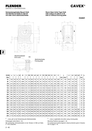


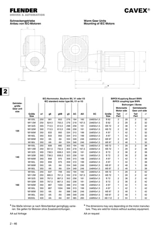


![CAVEX®
2 - 50
Schneckengetriebe
mit Schrumpfscheiben
Worm Gear Units
with shrink disks
Die Schutzhaube muß gesondert bestellt werden. Guard to be ordered seperately.
Größe
Size
Schrumpfscheibe / Shrink disk d7 d8 d9 d10 f1 G2 G4 l3 l4 l5 l6 l7
Typ(e) T2max
[Nm]
D
63 HSD 36 - 32 630 72 28 30 30 37 1 65 95 160 21 24 25 13
80 HSD 50 - 32 1400 90 39 40 40 48 0,5 80 112 192 25 28 30 13
100 HSD 68 - 32 2200 115 50 55 51 64 1 93 129 222 27 30 30 14
120 HSD 80 - 32 4600 141 60 65 61 75 1 106 144 250 29 32 32 16
140 HSD 90 - 32 6400 155 65 70 66 80 2 118 166 284 35 38 40 16
160 HSD 100 - 32 9700 170 75 80 77 90 2 132 184 316 40 43 45 16
180 HSD 110 - 32 14000 185 85 90 87 100 2 144 202 346 45 48 50 18
200 HSD 125 - 32 21200 215 95 100 97 110 2 155 216 371 48 51 50 19
225 HSD 140 - 32 29800 230 105 110 107 120 2 170 238 408 53 56 60 20
250 HSD 155 - 32 40000 263 115 120 117 130 2 185 257 442 57 60 60 20
280 HSD 165 - 32 51000 290 125 130 127 140 2 200 280 480 63 66 65 22
315 HSD 185 - 32 79000 320 140 150 142 160 2 220 317 537 78 82 80 23
355 HSD 200 - 32 95000 340 155 160 157 170 2 242 340 582 78 82 80
AA
400 HSD 240 - 32 148000 405 175 180 177 190 2 265 385 650 98 102 100
450 HSD 260 - 32 215000 430 200 205 202 215 2 292 425 717 112 116 120
500 HSD 280 - 32 279000 460 220 225 222 235 2 320 467 787 125 130 135
560 HSD 320 - 32 346000 520 240 245 242 255 2 352 507 859 134 140 145
630 HSD 340 - 32 489000 570 270 275 272 285 2 388 558 946 148 155 160
AA auf Anfrage AA on request
Schutzhaube
Guard
Schrumpfscheibe
Shrink disk
Gleitbuchse
Sliding bush
Anschlußmaße für Welle
Fitting dimensions for shaft](https://image.slidesharecdn.com/flendercavex-170315053907/85/CAVEX-Flender-Siemens-81-320.jpg)

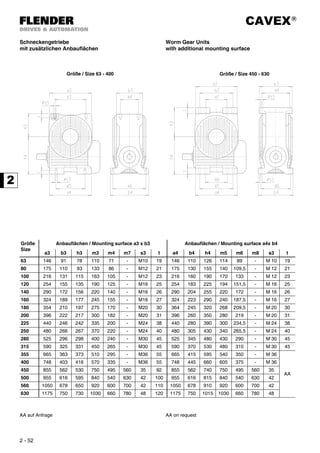

![CAVEX®
2 - 54
Schneckengetriebe
Entlüftung, Ölstand, Ölablaß
Worm Gear Units
Vent, oil level and oil drain
Größe / Size 63 80 100 120 140/160 180/200 225/250 280/315 355/400 450/500 560/630
X [mm] 60 70 82 95 110 135 160 190 210 240 280
Bei senkrechter Schneckenwelle muß oberhalb des Getriebes
bei M6 bzw. M7 ein Freiraum von der Höhe X vorgesehen
werden.
Position von M6 ist abhängig von der Baulage und Abtriebs-
seite.
For vertical worm shaft arrangement, a space of dimension X
must be left above the gear unit at M6 or M7.
Position M6 is depending on the mounting position and the
side of the output shaft.
Einbaulage / Mounting positions
Bauart Abtrieb auf Seite SU SO SR SL VO VU
Type Output on side ⊗ ⊗ ⊗ ⊗ ⊗ ⊗
CUW
CUA
A A1 B21) B3 B3 B2 A1 B4 M1 A1 A1 M1 B4 M6 B5 M7 M7 B7 M6
B / beiderseits
on both sides
B1 A21)
A3 A3 A2 B1 B1 M1 A4 A4 M1 B1 M6 A7 M7 M7 A5 M6
COW
COA
A B4 B21)
B6 B6 B2 B4 B4 M2/3 A4 A4 M2/3 B4 M6 B5 M7 M7 B7 M6
B / beiderseits
on both sides
A4 A21)
A6 A6 A2 A4 B4 M2/3 A4 A4 M2/3 B4 M6 A7 M7 M7 A5 M6
CFW 2)
CFA
CDA
A A1 B21)
B6 B6 B2 A1 B4 M1 A1 A1 M1 B4 M6 B5 M7 M7 B7 M6
B / beiderseits
on both sides
B1 A21)
A6 A6 A2 B1 B1 M1 A4 A4 M1 B1 M6 A7 M7 M7 A5 M6
Lage der Entlüftung Location of vent
⊗ Lage des Ölstands ⊗ Location of oil level
Lage des Ölablasses Location of oil drain
1)
Bei Größen 63 und 80: B5 statt B2 bzw. A5 statt A2 1)
For sizes 63 and 80: B5 instead of B2, and A5 instead of A2
2)
Bei Bauart CFW ist der Flansch als Abtrieb definiert. 2)
For type CFW, the flange is designed as output.
B4
B5 B7
B2
B3
B6
M3
M7
M2
M6
A1 M1 B1
A4
A2
A5 A7
A6
M2
M6
M3
M7
A3
M6 M6](https://image.slidesharecdn.com/flendercavex-170315053907/85/CAVEX-Flender-Siemens-85-320.jpg)
![CAVEX®
2 - 55
Schneckengetriebe
Durchschnittliche Ölmengen und Gewichte
Worm Gear Units
Average Oil quantities and Weights
Größe
Size
Ölmengen / oil quantities
[ l ]
Gewichte ohne Öl /weights without oil
[kg]
Bauart / Type CUW, COW, CFW
Einbaulage / Mouting position
Bauart / Type CUA, COA, CFA, CDA
Einbaulage / Mouting positions
Bauart / Type
SU SO SR/SL VO/VU SU SO SR/SL VO/VU C.W C.A
63 0,6 0,8 0,7 1,1 0,6 0,7 0,6 1 15 15
80 1,2 1,8 1,3 2,2 1,2 1,6 1,1 2 25 25
100 1,3 3,3 2,3 4,2 1,3 3 2 3,8 42 40
120 2 5,5 4 7 2 5 3,5 6,5 65 62
140 3 9 6 11 3 8 5,5 10 90 85
160 4,5 12,5 85 16 4,5 11,5 8 15 125 120
180 5,5 17 12 22 5,5 16 11 20 170 160
200 7,5 23 16 29 7,5 22 15 27 220 210
225 10 32 21 39 10 29 20 36 290 270
250 13 44 27 52 13 40 26 47 380 360
280 15 58 35 66 15 54 33 62 520 490
315 20 78 50 88 20 72 47 82 700 660
355 28 110 71 124 28 102 68 116 1030 980
400 40 155 95 174 40 145 90 164 1400 1340
450 55 220 133 243 55 108 127 132 1980 1910
500 77 310 186 340 77 295 178 325 2700 2620
560 108 430 260 475 108 410 250 455 3700 3600
630 150 600 360 665 150 575 348 640 5000 4880](https://image.slidesharecdn.com/flendercavex-170315053907/85/CAVEX-Flender-Siemens-86-320.jpg)
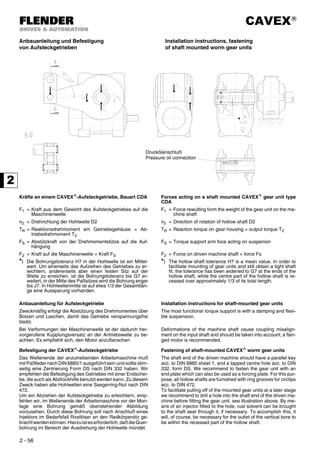


![CAVEX®
3 - 4
Leistungen und Drehmomente Power Ratings and Torques
Stirnradschneckengetriebe Größe 63 Helical Worm Gear Units size 63
Legende / Erläuterungen siehe Seite 3 - 3 Legend / explanations see page 3 - 3
i1 x i2
γm
n1
[1/min]
n2
[1/min]
P1N
[kW]
T2N
[Nm]
T2max
[Nm]
f7
[-]
η
[%]
i1 x i2
γm
n1
[1/min]
n2
[1/min]
P1N
[kW]
T2N
[Nm]
T2max
[Nm]
f7
[-]
η
[%]
2,080
x
10,33
=
21,49
ca.
18°
3000 140 3,55 218 309
0,530
90
2,545
x
15,50
=
39,45
ca.
12°
3000 76,0 2,40 258 350
0,530
86
2400 112 3,13 238 334 89 2400 60,8 2,08 277 372 85
1800 83,8 2,61 262 363 88 1800 45,6 1,70 297 397 83
1500 69,8 2,30 276 379 88 1500 38,0 1,49 309 411 83
1200 55,8 1,96 290 397 86 1200 30,4 1,25 321 426 82
1000 46,5 1,70 300 409 86 1000 25,3 1,08 330 436 81
750 34,9 1,35 314 425 85 750 19,0 0,850 341 449 80
500 23,3 0,953 329 443 84 500 12,7 0,590 353 464 80
300 14,0 0,601 342 458 83 300 7,60 0,371 363 476 78
150 6,98 0,315 352 470 82 150 3,80 0,194 371 485 76
2,545
x
10,33
=
26,30
ca.
18°
3000 114 3,17 236 332
0,530
89
3,174
x
15,50
=
49,20
ca.
12°
3000 61,0 2,09 277 372
0,530
85
2400 91,3 2,77 255 355 88 2400 48,8 1,79 293 392 84
1800 68,4 2,27 277 381 87 1800 36,6 1,44 311 414 83
1500 57,0 1,99 289 395 87 1500 30,5 1,26 321 425 81
1200 45,6 1,68 301 410 86 1200 24,4 1,05 331 438 81
1000 38,0 1,45 310 421 85 1000 20,3 0,902 338 446 80
750 28,5 1,14 322 435 84 750 15,2 0,698 348 458 79
500 19,0 0,794 335 450 84 500 10,2 0,485 358 469 79
300 11,4 0,499 346 462 83 300 6,10 0,302 366 479 77
150 5,70 0,260 354 472 81 150 3,05 0,158 372 487 75
2,080
x
15,50
=
32,24
ca.
12°
3000 93,1 2,70 240 328
0,530
87
2,080
x
31
=
64,48
ca.
6,1°
3000 46,5 1,66 265 346
0,530
78
2400 74,4 2,37 260 352 85 2400 37,2 1,45 285 370 77
1800 55,8 1,96 283 380 84 1800 27,9 1,21 307 397 74
1500 46,5 1,73 296 396 83 1500 23,3 1,06 320 412 74
1200 37,2 1,46 310 412 83 1200 18,6 0,903 333 429 72
1000 31,0 1,27 320 424 82 1000 15,5 0,788 343 440 71
750 23,3 1,01 333 440 80 750 11,6 0,630 355 455 68
500 15,5 0,709 347 457 79 500 7,75 0,442 369 472 68
300 9,31 0,447 359 471 78 300 4,65 0,281 380 486 66
150 4,65 0,235 369 483 76 150 2,33 0,149 389 497 64](https://image.slidesharecdn.com/flendercavex-170315053907/85/CAVEX-Flender-Siemens-91-320.jpg)
![CAVEX®
3 - 5
Stirnradschneckengetriebe Größe 63 Helical Worm Gear Units size 63
Legende / Erläuterungen siehe Seite 3 - 3 Legend / explanations see page 3 - 3
i1 x i2
γm
n1
[1/min]
n2
[1/min]
P1N
[kW]
T2N
[Nm]
T2max
[Nm]
f7
[-]
η
[%]
i1 x i2
γm
n1
[1/min]
n2
[1/min]
P1N
[kW]
T2N
[Nm]
T2max
[Nm]
f7
[-]
η
[%]
2,545
x
31
=
78,90
ca.
6,1°
3000 38,0 1,47 283 368
0,530
77
4,706
x
39
=
183,50
ca.
5,2°
3000 16,3 0,768 311 399
0,530
69
2400 30,4 1,28 301 389 75 2400 13,1 0,652 322 413 68
1800 22,8 1,05 321 414 73 1800 9,81 0,523 334 427 66
1500 19,0 0,917 332 427 72 1500 8,17 0,448 340 435 65
1200 15,2 0,777 344 441 70 1200 6,54 0,367 346 442 65
1000 12,7 0,674 352 451 69 1000 5,45 0,311 350 448 64
750 9,51 0,530 363 464 68 750 4,09 0,242 356 454 63
500 6,34 0,369 374 478 67 500 2,72 0,168 362 461 61
300 3,80 0,233 383 490 65 300 1,63 0,105 366 467 59
150 1,90 0,124 391 499 63 150 0,817 0,057 370 472 56
3,174
x
31
=
98,39
ca.
6,1°
3000 30,5 1,28 301 389
0,530
75
4,706
x
49
=
230,60
ca.
4,4°
3000 13,0 0,610 293 376
0,530
65
2400 24,4 1,10 317 409 74 2400 10,4 0,518 303 388 64
1800 18,3 0,892 334 430 72 1800 7,81 0,416 314 401 62
1500 15,2 0,778 344 441 70 1500 6,50 0,355 319 408 61
1200 12,2 0,654 353 453 69 1200 5,20 0,291 325 415 61
1000 10,2 0,562 360 461 68 1000 4,34 0,247 328 419 60
750 7,62 0,436 369 472 68 750 3,25 0,192 333 425 59
500 5,08 0,304 379 484 66 500 2,17 0,133 338 432 58
300 3,05 0,191 386 493 65 300 1,30 0,084 342 437 55
150 1,52 0,102 392 500 61 150 0,650 0,046 346 441 51
4,053
x
31
=
125,60
ca.
6,1°
3000 23,9 1,08 318 410
0,530
74
4,706
x
61
=
287,10
ca.
3,°8
3000 10,4 0,492 277 355
0,530
61
2400 19,1 0,920 332 427 72 2400 8,36 0,408 279 357 60
1800 14,3 0,741 346 445 70 1800 6,27 0,317 280 358 58
1500 11,9 0,643 354 454 69 1500 5,22 0,267 280 358 57
1200 9,55 0,533 362 464 68 1200 4,18 0,215 280 358 57
1000 7,96 0,453 368 471 68 1000 3,48 0,181 280 358 56
750 5,97 0,350 375 480 67 750 2,61 0,140 281 358 55
500 3,98 0,243 383 489 66 500 1,74 0,095 281 358 54
300 2,39 0,153 389 496 64 300 1,04 0,060 281 358 51
150 1,19 0,082 394 502 60 150 0,522 0,032 281 359 48
4,706
x
31
=
145,90
ca.
6,1°
3000 20,6 0,972 327 422
0,530
73
2400 16,4 0,824 340 437 71
1800 12,3 0,660 353 453 69
1500 10,3 0,568 360 461 68
1200 8,22 0,467 367 470 68
1000 6,85 0,396 372 476 67
750 5,14 0,307 378 483 66
500 3,43 0,212 385 491 65
300 2,06 0,133 390 498 63
150 1,03 0,071 394 503 60](https://image.slidesharecdn.com/flendercavex-170315053907/85/CAVEX-Flender-Siemens-92-320.jpg)
![CAVEX®
3 - 6
Stirnradschneckengetriebe Größe 80 Helical Worm Gear Units size 80
Legende / Erläuterungen siehe Seite 3 - 3 Legend / explanations see page 3 - 3
i1 x i2
γm
n1
[1/min]
n2
[1/min]
P1N
[kW]
T2N
[Nm]
T2max
[Nm]
f7
[-]
η
[%]
i1 x i2
γm
n1
[1/min]
n2
[1/min]
P1N
[kW]
T2N
[Nm]
T2max
[Nm]
f7
[-]
η
[%]
2,080
x
10,33
=
21,49
ca.
18°
3000 140 6,49 402 574
0,530
91
2,545
x
15,50
=
39,45
ca.
12°
3000 76,0 4,39 480 653
0,530
87
2400 112 5,77 444 626 90 2400 60,8 3,83 519 702 86
1800 83,8 4,86 495 689 89 1800 45,6 3,16 564 757 85
1500 69,8 4,31 523 724 89 1500 38,0 2,77 589 788 85
1200 55,8 3,68 555 763 88 1200 30,4 2,34 616 821 84
1000 46,5 3,21 578 791 88 1000 25,3 2,03 636 845 83
750 34,9 2,56 609 828 87 750 19,0 1,60 661 876 82
500 23,3 1,82 643 869 86 500 12,7 1,12 689 910 82
300 14,0 1,15 672 905 86 300 7,60 0,708 712 938 80
150 6,98 0,607 695 933 84 150 3,80 0,372 731 961 78
2,545
x
10,33
=
26,30
ca.
18°
3000 114 5,84 440 621
0,530
90
3,174
x
15,50
=
49,20
ca.
12°
3000 61,0 3,83 519 701
0,530
87
2400 91,3 5,13 480 671 89 2400 48,8 3,31 554 745 86
1800 68,4 4,25 526 727 89 1800 36,6 2,69 594 794 85
1500 57,0 3,73 552 759 88 1500 30,5 2,34 616 821 84
1200 45,6 3,16 580 793 88 1200 24,4 1,96 639 849 83
1000 38,0 2,74 600 818 87 1000 20,3 1,69 656 869 83
750 28,5 2,17 627 850 86 750 15,2 1,33 677 896 81
500 19,0 1,53 656 885 85 500 10,2 0,920 700 924 81
300 11,4 0,960 680 915 85 300 6,10 0,577 720 947 80
150 5,70 0,503 700 939 83 150 3,05 0,303 735 966 77
2,080
x
15,50
=
32,24
ca.
12°
3000 93,1 4,91 441 606
0,530
88
2,080
x
31
=
64,48
ca.
6,2°
3000 46,5 3,00 490 642 0,544 80
2400 74,4 4,34 484 658 87 2400 37,2 2,63 531 693
0,530
79
1800 55,8 3,62 533 719 86 1800 27,9 2,20 580 753 77
1500 46,5 3,20 561 754 85 1500 23,3 1,94 608 787 76
1200 37,2 2,72 592 791 85 1200 18,6 1,65 638 824 75
1000 31,0 2,37 614 818 84 1000 15,5 1,44 659 851 74
750 23,3 1,89 644 855 83 750 11,6 1,15 688 886 73
500 15,5 1,35 676 894 81 500 7,75 0,826 719 925 71
300 9,31 0,850 704 929 81 300 4,65 0,524 746 958 69
150 4,65 0,449 727 956 79 150 2,33 0,280 768 984 67](https://image.slidesharecdn.com/flendercavex-170315053907/85/CAVEX-Flender-Siemens-93-320.jpg)
![CAVEX®
3 - 7
Stirnradschneckengetriebe Größe 80 Helical Worm Gear Units size 80
Legende / Erläuterungen siehe Seite 3 - 3 Legend / explanations see page 3 - 3
i1 x i2
γm
n1
[1/min]
n2
[1/min]
P1N
[kW]
T2N
[Nm]
T2max
[Nm]
f7
[-]
η
[%]
i1 x i2
γm
n1
[1/min]
n2
[1/min]
P1N
[kW]
T2N
[Nm]
T2max
[Nm]
f7
[-]
η
[%]
2,545
x
31
=
78,90
ca.
6,2°
3000 38,0 2,67 528 688
0,530
79
4,706
x
39
=
183,50
ca.
5,4°
3000 16,3 1,43 609 786
0,530
73
2400 30,4 2,32 566 736 78 2400 13,1 1,21 634 818 72
1800 22,8 1,91 610 791 76 1800 9,81 0,972 661 851 70
1500 19,0 1,68 635 821 75 1500 8,17 0,841 676 869 69
1200 15,2 1,42 661 853 74 1200 6,54 0,697 691 888 68
1000 12,7 1,24 680 876 73 1000 5,45 0,593 701 901 67
750 9,51 0,982 705 907 71 750 4,09 0,458 715 917 67
500 6,34 0,691 731 940 70 500 2,72 0,320 729 934 65
300 3,80 0,438 754 967 68 300 1,63 0,201 740 949 63
150 1,90 0,233 772 989 66 150 0,817 0,108 749 960 59
3,174
x
31
=
98,39
ca.
6,2°
3000 30,5 2,32 566 736
0,530
78
4,706
x
49
=
230,60
ca.
4,6°
3000 13,0 1,12 573 739
0,530
70
2400 24,4 2,00 601 779 77 2400 10,4 0,951 595 766 68
1800 18,3 1,63 640 827 75 1800 7,81 0,762 619 796 66
1500 15,2 1,42 661 853 74 1500 6,50 0,661 632 812 65
1200 12,2 1,20 684 881 73 1200 5,20 0,545 645 829 64
1000 10,2 1,04 699 900 72 1000 4,34 0,464 654 840 64
750 7,62 0,814 720 926 71 750 3,25 0,360 666 855 63
500 5,08 0,566 742 953 70 500 2,17 0,251 678 870 61
300 3,05 0,358 761 976 68 300 1,30 0,158 688 882 59
150 1,52 0,191 775 994 65 150 0,650 0,086 696 892 55
4,053
x
31
=
125,60
ca.
6,2°
3000 23,9 1,98 604 783
0,530
76
4,706
x
61
=
287,10
ca.
3,9°
3000 10,4 0,897 540 696
0,530
66
2400 19,1 1,69 634 820 75 2400 8,36 0,761 560 721 64
1800 14,3 1,36 668 861 74 1800 6,27 0,595 567 728 63
1500 11,9 1,18 686 883 72 1500 5,22 0,507 568 729 61
1200 9,55 0,986 704 907 71 1200 4,18 0,410 568 729 61
1000 7,96 0,845 717 923 71 1000 3,48 0,344 568 729 60
750 5,97 0,655 735 944 70 750 2,61 0,263 569 730 59
500 3,98 0,456 752 965 69 500 1,74 0,181 569 730 57
300 2,39 0,286 767 984 67 300 1,04 0,113 570 730 55
150 1,19 0,153 779 998 63 150 0,522 0,061 570 731 51
4,706
x
31
=
145,90
ca.
6,2°
3000 20,6 1,78 625 808
0,530
76
2400 16,4 1,51 652 842 74
1800 12,3 1,21 683 880 73
1500 10,3 1,05 699 899 72
1200 8,22 0,870 715 920 71
1000 6,85 0,741 727 934 70
750 5,14 0,571 742 953 70
500 3,43 0,399 757 972 68
300 2,06 0,250 770 988 66
150 1,03 0,134 780 1000 63](https://image.slidesharecdn.com/flendercavex-170315053907/85/CAVEX-Flender-Siemens-94-320.jpg)
![CAVEX®
3 - 8
Stirnradschneckengetriebe Größe 100 Helical Worm Gear Units size 100
Legende / Erläuterungen siehe Seite 3 - 3 Legend / explanations see page 3 - 3
i1 x i2
γm
n1
[1/min]
n2
[1/min]
P1N
[kW]
T2N
[Nm]
T2max
[Nm]
f7
[-]
η
[%]
i1 x i2
γm
n1
[1/min]
n2
[1/min]
P1N
[kW]
T2N
[Nm]
T2max
[Nm]
f7
[-]
η
[%]
1,963
x
10,67
=
20,94
ca.
18°
3000 143 11,5 699 1010
0,530
91
2,478
x
16,50
=
40,89
ca.
12°
3000 73,4 7,60 866 1180 0,540 88
2400 115 10,4 783 1110 91 2400 58,7 6,67 945 1280
0,530
87
1800 86,0 8,84 886 1240 90 1800 44,0 5,53 1040 1400 87
1500 71,6 7,89 946 1320 90 1500 36,7 4,87 1090 1470 86
1200 57,3 6,79 1010 1400 89 1200 29,3 4,13 1150 1540 85
1000 47,8 5,96 1060 1460 89 1000 24,5 3,58 1190 1590 85
750 35,8 4,78 1130 1550 89 750 18,3 2,84 1250 1660 84
500 23,9 3,43 1210 1640 88 500 12,2 2,01 1310 1740 83
300 14,3 2,20 1270 1730 86 300 7,34 1,27 1360 1810 82
150 7,16 1,16 1330 1790 86 150 3,67 0,671 1400 1860 80
2,478
x
10,67
=
26,43
ca.
18°
3000 114 10,3 787 1120
0,530
91
3,217
x
16,50
=
53,08
ca.
12°
3000 56,5 6,51 958 1300
0,530
87
2400 90,8 9,13 867 1220 90 2400 45,2 5,63 1030 1390 87
1800 68,1 7,63 962 1340 90 1800 33,9 4,60 1110 1500 86
1500 56,8 6,74 1020 1410 90 1500 28,3 4,01 1160 1550 86
1200 45,4 5,74 1080 1480 89 1200 22,6 3,37 1210 1610 85
1000 37,8 4,99 1120 1530 89 1000 18,8 2,90 1240 1660 84
750 28,4 3,96 1180 1610 89 750 14,1 2,28 1290 1720 84
500 18,9 2,81 1240 1680 87 500 9,42 1,59 1340 1780 83
300 11,4 1,78 1300 1750 87 300 5,65 1,00 1380 1830 82
150 5,68 0,935 1340 1810 85 150 2,83 0,526 1410 1870 79
1,963
x
16,50
=
32,39
ca.
12°
3000 92,6 8,53 777 1070 0,568 88
1,963
x
32
=
62,82
ca.
6,3°
3000 47,8 5,24 851 1120 0,624 81
2400 74,1 7,64 862 1180 0,542 88 2400 38,2 4,69 936 1230 0,589 80
1800 55,6 6,45 964 1310
0,530
87 1800 28,7 3,94 1040 1360 0,542 79
1500 46,3 5,72 1020 1380 86 1500 23,9 3,49 1100 1430
0,530
79
1200 37,0 4,90 1090 1470 86 1200 19,1 2,99 1160 1510 78
1000 30,9 4,29 1140 1530 86 1000 15,9 2,62 1210 1570 77
750 23,2 3,43 1200 1610 85 750 11,9 2,10 1280 1650 76
500 15,4 2,46 1280 1700 84 500 7,96 1,51 1350 1740 75
300 9,26 1,57 1340 1780 83 300 4,78 0,970 1410 1820 73
150 4,63 0,833 1390 1840 81 150 2,39 0,520 1460 1880 70](https://image.slidesharecdn.com/flendercavex-170315053907/85/CAVEX-Flender-Siemens-95-320.jpg)
![CAVEX®
3 - 9
Stirnradschneckengetriebe Größe 100 Helical Worm Gear Units size 100
Legende / Erläuterungen siehe Seite 3 - 3 Legend / explanations see page 3 - 3
i1 x i2
γm
n1
[1/min]
n2
[1/min]
P1N
[kW]
T2N
[Nm]
T2max
[Nm]
f7
[-]
η
[%]
i1 x i2
γm
n1
[1/min]
n2
[1/min]
P1N
[kW]
T2N
[Nm]
T2max
[Nm]
f7
[-]
η
[%]
2,478
x
32
=
79,30
ca.
6,3°
3000 37,8 4,67 940 1230 0,588 80
5,063
x
40
=
202,50
ca.
5,5°
3000 14,8 2,35 1140 1480
0,530
75
2400 30,3 4,08 1020 1330 0,551 79 2400 11,9 1,99 1190 1540 75
1800 22,7 3,37 1110 1450
0,530
78 1800 8,89 1,59 1250 1610 73
1500 18,9 2,97 1170 1520 78 1500 7,41 1,37 1280 1650 72
1200 15,1 2,52 1220 1590 77 1200 5,93 1,14 1310 1690 71
1000 12,6 2,19 1260 1640 76 1000 4,94 0,971 1330 1720 71
750 9,46 1,74 1320 1710 75 750 3,70 0,752 1360 1750 70
500 6,31 1,24 1380 1780 74 500 2,47 0,525 1390 1790 68
300 3,78 0,786 1430 1850 72 300 1,48 0,331 1410 1820 66
150 1,89 0,421 1470 1900 69 150 0,741 0,178 1430 1840 62
3,217
x
32
=
102,90
ca.
6,3°
3000 29,2 3,98 1030 1350 0,544 79
5,063
x
50
=
253,20
ca.
4,7°
3000 11,8 1,84 1070 1390
0,530
72
2400 23,3 3,44 1100 1440
0,530
78 2400 9,48 1,56 1120 1450 71
1800 17,5 2,80 1190 1540 78 1800 7,11 1,24 1170 1510 70
1500 14,6 2,45 1230 1600 77 1500 5,92 1,07 1200 1540 70
1200 11,7 2,06 1280 1660 76 1200 4,74 0,892 1220 1580 68
1000 9,72 1,78 1310 1700 75 1000 3,95 0,760 1240 1600 67
750 7,29 1,40 1360 1760 74 750 2,96 0,588 1270 1630 67
500 4,86 0,984 1410 1820 73 500 1,97 0,412 1290 1670 65
300 2,92 0,624 1450 1870 71 300 1,18 0,259 1300 1680 62
150 1,46 0,333 1480 1910 68 150 0,592 0,139 1300 1680 58
4,105
x
32
=
131,40
ca.
6,3°
3000 22,8 3,39 1110 1450
0,530
78
5,063
x
62
=
313,90
ca.
4,0°
3000 9,56 1,47 1010 1310
0,530
69
2400 18,3 2,89 1170 1530 78 2400 7,65 1,24 1050 1360 68
1800 13,7 2,33 1250 1620 77 1800 5,73 0,963 1070 1380 67
1500 11,4 2,02 1280 1660 76 1500 4,78 0,815 1070 1380 66
1200 9,13 1,69 1320 1710 75 1200 3,82 0,663 1070 1380 65
1000 7,61 1,46 1350 1750 74 1000 3,19 0,558 1070 1380 64
750 5,71 1,14 1390 1800 73 750 2,39 0,424 1070 1380 63
500 3,81 0,791 1430 1850 72 500 1,59 0,293 1070 1380 61
300 2,28 0,499 1460 1890 70 300 0,956 0,183 1070 1380 59
150 1,14 0,267 1490 1920 67 150 0,478 0,099 1070 1380 54
5,063
x
32
=
162,00
ca.
6,3°
3000 18,5 2,92 1170 1520
0,530
78
2400 14,8 2,48 1230 1590 77
1800 11,1 1,98 1290 1670 76
1500 9,26 1,71 1320 1710 75
1200 7,41 1,42 1360 1760 74
1000 6,17 1,22 1380 1790 73
750 4,63 0,943 1410 1820 72
500 3,09 0,656 1450 1870 72
300 1,85 0,413 1470 1900 69
150 0,926 0,221 1490 1930 65](https://image.slidesharecdn.com/flendercavex-170315053907/85/CAVEX-Flender-Siemens-96-320.jpg)
![CAVEX®
3 - 10
Stirnradschneckengetriebe Größe 120 Helical Worm Gear Units size 120
Legende / Erläuterungen siehe Seite 3 - 3 Legend / explanations see page 3 - 3
i1 x i2
γm
n1
[1/min]
n2
[1/min]
P1N
[kW]
T2N
[Nm]
T2max
[Nm]
f7
[-]
η
[%]
i1 x i2
γm
n1
[1/min]
n2
[1/min]
P1N
[kW]
T2N
[Nm]
T2max
[Nm]
f7
[-]
η
[%]
1,963
x
10,67
=
20,94
ca.
19°
3000 143 18,0 1100 1590 0,560 92
2,478
x
16,50
=
40,89
ca.
12°
3000 73,4 12,0 1380 1900 0,596 88
2400 115 16,4 1250 1780 0,540 92 2400 58,7 10,7 1520 2080 0,566 87
1800 86,0 14,1 1420 2010
0,530
91 1800 44,0 8,90 1690 2300
0,530
87
1500 71,6 12,7 1530 2140 90 1500 36,7 7,86 1790 2420 88
1200 57,3 11,0 1650 2300 90 1200 29,3 6,68 1890 2550 87
1000 47,8 9,65 1740 2410 90 1000 24,5 5,81 1970 2650 87
750 35,8 7,78 1870 2570 90 750 18,3 4,61 2080 2780 86
500 23,9 5,60 2010 2750 90 500 12,2 3,27 2190 2930 86
300 14,3 3,61 2130 2910 88 300 7,34 2,08 2290 3060 85
150 7,16 1,92 2240 3040 87 150 3,67 1,10 2380 3160 83
2,478
x
10,67
=
26,43
ca.
19°
3000 114 16,3 1250 1790 0,538 92
3,217
x
16,50
=
53,08
ca.
12°
3000 56,5 10,4 1550 2110 0,559 88
2400 90,8 14,6 1390 1970
0,530
91 2400 45,2 9,06 1680 2280
0,530
88
1800 68,1 12,3 1560 2180 90 1800 33,9 7,42 1830 2470 88
1500 56,8 10,9 1660 2300 91 1500 28,3 6,49 1910 2570 87
1200 45,4 9,30 1760 2440 90 1200 22,6 5,46 2000 2690 87
1000 37,8 8,11 1840 2540 90 1000 18,8 4,71 2070 2770 87
750 28,4 6,46 1950 2680 90 750 14,1 3,70 2160 2880 86
500 18,9 4,60 2070 2830 89 500 9,42 2,60 2250 3000 85
300 11,4 2,93 2180 2960 89 300 5,65 1,64 2330 3100 84
150 5,68 1,54 2260 3070 87 150 2,83 0,864 2400 3190 82
1,963
x
16,50
=
32,39
ca.
12°
3000 92,6 13,4 1230 1710 0,628 89
1,963
x
32
=
62,82
ca.
6,4°
3000 47,8 8,19 1350 1790 0,686 83
2400 74,1 12,1 1380 1900 0,599 88 2400 38,2 7,37 1500 1980 0,651 81
1800 55,6 10,3 1560 2120 0,556 88 1800 28,7 6,28 1680 2200 0,597 80
1500 46,3 9,21 1660 2260
0,530
87 1500 23,9 5,57 1780 2340 0,566 80
1200 37,0 7,91 1780 2410 87 1200 19,1 4,77 1900 2490
0,530
80
1000 30,9 6,93 1870 2520 87 1000 15,9 4,18 1990 2600 79
750 23,2 5,56 1990 2680 87 750 11,9 3,35 2110 2750 78
500 15,4 3,99 2130 2850 86 500 7,96 2,40 2250 2920 78
300 9,26 2,56 2250 3010 85 300 4,78 1,55 2370 3080 77
150 4,63 1,37 2350 3130 83 150 2,39 0,836 2470 3200 74](https://image.slidesharecdn.com/flendercavex-170315053907/85/CAVEX-Flender-Siemens-97-320.jpg)
![CAVEX®
3 - 11
Stirnradschneckengetriebe Größe 120 Helical Worm Gear Units size 120
Legende / Erläuterungen siehe Seite 3 - 3 Legend / explanations see page 3 - 3
i1 x i2
γm
n1
[1/min]
n2
[1/min]
P1N
[kW]
T2N
[Nm]
T2max
[Nm]
f7
[-]
η
[%]
i1 x i2
γm
n1
[1/min]
n2
[1/min]
P1N
[kW]
T2N
[Nm]
T2max
[Nm]
f7
[-]
η
[%]
2,478
x
32
=
79,30
ca.
6,4°
3000 37,8 7,34 1500 1980 0,648 81
5,063
x
40
=
202,50
ca.
5,6°
3000 14,8 3,73 1860 2430
0,530
77
2400 30,3 6,49 1640 2160 0,606 80 2400 11,9 3,16 1960 2550 77
1800 22,7 5,38 1810 2370 0,558 80 1800 8,89 2,52 2060 2690 76
1500 18,9 4,74 1910 2490
0,530
80 1500 7,41 2,17 2120 2760 76
1200 15,1 4,02 2010 2630 79 1200 5,93 1,79 2180 2830 76
1000 12,6 3,50 2090 2730 79 1000 4,94 1,54 2220 2890 75
750 9,46 2,77 2190 2860 78 750 3,70 1,20 2280 2960 74
500 6,31 1,98 2310 3000 77 500 2,47 0,835 2330 3030 72
300 3,78 1,26 2410 3130 76 300 1,48 0,528 2380 3090 70
150 1,89 0,676 2490 3230 73 150 0,741 0,285 2420 3140 66
3,217
x
32
=
102,90
ca.
6,4°
3000 29,2 6,34 1670 2190 0,603 81
5,063
x
50
=
253,20
ca.
4,8°
3000 11,8 2,94 1780 2310
0,530
75
2400 23,3 5,48 1800 2350 0,562 80 2400 9,48 2,48 1860 2420 74
1800 17,5 4,47 1950 2540
0,530
80 1800 7,11 1,98 1960 2540 74
1500 14,6 3,91 2030 2650 79 1500 5,92 1,70 2010 2610 73
1200 11,7 3,28 2120 2760 79 1200 4,74 1,41 2060 2680 73
1000 9,72 2,84 2190 2850 78 1000 3,95 1,21 2100 2720 72
750 7,29 2,23 2270 2950 78 750 2,96 0,942 2150 2780 71
500 4,86 1,57 2370 3070 77 500 1,97 0,657 2200 2850 69
300 2,92 0,999 2450 3170 75 300 1,18 0,413 2220 2880 66
150 1,46 0,535 2510 3250 72 150 0,592 0,221 2220 2880 62
4,105
x
32
=
131,40
ca.
6,4°
3000 22,8 5,41 1810 2370 0,559 80
5,063
x
63
=
319,00
ca.
4,1°
3000 9,40 2,27 1660 2160
0,530
72
2400 18,3 4,62 1920 2520
0,530
80 2400 7,52 1,92 1740 2260 71
1800 13,7 3,73 2060 2680 79 1800 5,64 1,51 1800 2340 70
1500 11,4 3,23 2130 2770 79 1500 4,70 1,27 1800 2340 70
1200 9,13 2,70 2210 2870 78 1200 3,76 1,03 1800 2340 69
1000 7,61 2,31 2260 2940 78 1000 3,13 0,865 1800 2340 68
750 5,71 1,82 2330 3030 77 750 2,35 0,660 1800 2340 67
500 3,81 1,27 2410 3130 76 500 1,57 0,452 1800 2340 65
300 2,28 0,803 2470 3210 73 300 0,940 0,283 1810 2340 63
150 1,14 0,430 2520 3270 70 150 0,470 0,153 1810 2340 58
5,063
x
32
=
162,00
ca.
6,4°
3000 18,5 4,67 1920 2510
0,530
80
2400 14,8 3,96 2020 2640 79
1800 11,1 3,16 2140 2790 79
1500 9,26 2,73 2200 2870 78
1200 7,41 2,26 2270 2950 78
1000 6,17 1,94 2310 3010 77
750 4,63 1,51 2370 3080 76
500 3,09 1,05 2440 3160 75
300 1,85 0,663 2490 3230 73
150 0,926 0,356 2530 3280 69](https://image.slidesharecdn.com/flendercavex-170315053907/85/CAVEX-Flender-Siemens-98-320.jpg)
![CAVEX®
3 - 12
Stirnradschneckengetriebe Größe 140 Helical Worm Gear Units size 140
Legende / Erläuterungen siehe Seite 3 - 3 Legend / explanations see page 3 - 3
i1 x i2
γm
n1
[1/min]
n2
[1/min]
P1N
[kW]
T2N
[Nm]
T2max
[Nm]
f7
[-]
η
[%]
i1 x i2
γm
n1
[1/min]
n2
[1/min]
P1N
[kW]
T2N
[Nm]
T2max
[Nm]
f7
[-]
η
[%]
2,040
x
10,67
=
21,76
ca.
19°
3000 138 25,9 1660 2400 0,604 93
2,455
x
16,50
=
40,51
ca.
13°
3000 74,1 17,7 2030 2810 0,646 89
2400 110 23,7 1880 2700 0,582 91 2400 59,2 15,8 2260 3100 0,613 89
1800 82,7 20,6 2160 3060 0,548 91 1800 44,4 13,4 2530 3450 0,569 88
1500 68,9 18,5 2330 3280
0,530
91 1500 37,0 11,8 2690 3660 0,537 88
1200 55,1 16,1 2530 3530 91 1200 29,6 10,1 2870 3880
0,530
88
1000 46,0 14,2 2670 3720 91 1000 24,7 8,84 3000 4050 88
750 34,5 11,5 2880 3980 90 750 18,5 7,06 3180 4280 87
500 23,0 8,31 3110 4280 90 500 12,3 5,03 3380 4540 87
300 13,8 5,37 3320 4550 89 300 7,41 3,22 3550 4760 86
150 6,89 2,86 3500 4780 88 150 3,70 1,71 3700 4950 84
2,455
x
10,67
=
26,19
ca.
19°
3000 115 24,1 1840 2650 0,586 92
3,120
x
16,50
=
51,48
ca.
13°
3000 58,3 15,7 2270 3120 0,610 88
2400 91,6 21,7 2060 2940 0,561 91 2400 46,6 13,8 2490 3400 0,576 88
1800 68,7 18,5 2340 3290
0,530
91 1800 35,0 11,4 2740 3720
0,530
88
1500 57,3 16,5 2500 3490 91 1500 29,1 10,0 2880 3900 88
1200 45,8 14,2 2680 3720 91 1200 23,3 8,46 3040 4100 88
1000 38,2 12,4 2810 3900 91 1000 19,4 7,33 3150 4250 87
750 28,6 9,93 2990 4130 90 750 14,6 5,79 3300 4440 87
500 19,1 7,11 3200 4390 90 500 9,71 4,09 3470 4660 86
300 11,5 4,55 3380 4630 89 300 5,83 2,58 3610 4840 85
150 5,73 2,41 3530 4820 88 150 2,91 1,36 3730 4990 84
2,040
x
16,50
=
33,66
ca.
13°
3000 89,1 19,2 1840 2570 0,674 89
2,040
x
32
=
65,28
ca.
6,5°
3000 46,0 11,6 2020 2690 0,736 84
2400 71,3 17,4 2070 2860 0,642 89 2400 36,8 10,5 2250 2980 0,696 83
1800 53,5 15,0 2360 3230 0,599 88 1800 27,6 9,05 2530 3350 0,643 81
1500 44,6 13,4 2530 3450 0,568 88 1500 23,0 8,05 2710 3570 0,607 81
1200 35,7 11,5 2720 3700 0,531 88 1200 18,4 6,92 2900 3810 0,565 81
1000 29,7 10,1 2860 3880
0,530
88 1000 15,3 6,07 3040 4000 0,531 80
750 22,3 8,17 3060 4140 87 750 11,5 4,89 3240 4250
0,530
80
500 14,9 5,89 3290 4430 87 500 7,66 3,52 3470 4540 79
300 8,91 3,79 3500 4690 86 300 4,60 2,28 3670 4800 78
150 4,46 2,02 3670 4910 85 150 2,30 1,23 3840 5020 75](https://image.slidesharecdn.com/flendercavex-170315053907/85/CAVEX-Flender-Siemens-99-320.jpg)
![CAVEX®
3 - 13
Stirnradschneckengetriebe Größe 140 Helical Worm Gear Units size 140
Legende / Erläuterungen siehe Seite 3 - 3 Legend / explanations see page 3 - 3
i1 x i2
γm
n1
[1/min]
n2
[1/min]
P1N
[kW]
T2N
[Nm]
T2max
[Nm]
f7
[-]
η
[%]
i1 x i2
γm
n1
[1/min]
n2
[1/min]
P1N
[kW]
T2N
[Nm]
T2max
[Nm]
f7
[-]
η
[%]
2,455
x
32
=
78,56
ca.
6,5°
3000 38,2 10,7 2210 2930 0,704 83
4,857
x
41
=
199,10
ca.
5,6°
3000 15,1 5,64 2800 3680 0,565 78
2400 30,5 9,57 2430 3220 0,661 81 2400 12,1 4,80 2970 3890
0,530
78
1800 22,9 8,04 2710 3570 0,606 81 1800 9,04 3,85 3150 4130 77
1500 19,1 7,11 2870 3770 0,576 81 1500 7,53 3,33 3250 4250 77
1200 15,3 6,06 3050 4000
0,530
81 1200 6,03 2,77 3360 4390 77
1000 12,7 5,29 3180 4170 80 1000 5,02 2,37 3430 4480 76
750 9,55 4,22 3350 4390 79 750 3,77 1,85 3530 4610 75
500 6,36 3,01 3550 4650 79 500 2,51 1,29 3630 4740 74
300 3,82 1,94 3730 4870 77 300 1,51 0,820 3720 4850 72
150 1,91 1,04 3870 5050 74 150 0,753 0,441 3790 4940 68
3,120
x
32
=
99,84
ca.
6,5°
3000 30,0 9,49 2450 3240 0,659 81
4,857
x
51
=
247,70
ca.
4,9°
3000 12,1 4,41 2640 3470 0,533 76
2400 24,0 8,29 2660 3510 0,616 81 2400 9,69 3,75 2790 3660
0,530
75
1800 18,0 6,83 2910 3830 0,562 80 1800 7,27 3,00 2950 3860 75
1500 15,0 5,99 3060 4020
0,530
80 1500 6,06 2,59 3040 3980 74
1200 12,0 5,06 3210 4210 80 1200 4,84 2,15 3140 4100 74
1000 10,0 4,39 3330 4360 79 1000 4,04 1,85 3200 4180 73
750 7,51 3,47 3480 4550 79 750 3,03 1,44 3290 4290 72
500 5,01 2,46 3650 4760 78 500 2,02 1,01 3380 4410 71
300 3,00 1,56 3790 4950 76 300 1,21 0,633 3420 4460 68
150 1,50 0,835 3910 5090 74 150 0,606 0,337 3420 4460 64
3,905
x
32
=
125,00
ca.
6,5°
3000 24,0 8,28 2660 3520 0,615 81
4,857
x
64
=
310,80
ca.
4,1°
3000 9,65 3,43 2480 3240
0,530
73
2400 19,2 7,14 2860 3770 0,573 81 2400 7,72 2,91 2610 3410 73
1800 14,4 5,80 3090 4050 0,530 80 1800 5,79 2,30 2730 3570 72
1500 12,0 5,06 3210 4220
0,530
80 1500 4,83 1,93 2730 3570 72
1200 9,60 4,24 3350 4390 79 1200 3,86 1,56 2730 3570 71
1000 8,00 3,65 3450 4510 79 1000 3,22 1,32 2730 3570 70
750 6,00 2,87 3580 4680 78 750 2,41 1,00 2740 3570 69
500 4,00 2,02 3720 4850 77 500 1,61 0,685 2740 3570 67
300 2,40 1,28 3840 5010 75 300 0,965 0,426 2740 3570 65
150 1,20 0,684 3930 5130 72 150 0,483 0,230 2740 3570 60
4,857
x
32
=
155,40
ca.
6,5°
3000 19,3 7,16 2860 3760 0,575 81
2400 15,4 6,11 3040 3990 0,534 80
1800 11,6 4,92 3240 4250
0,530
80
1500 9,65 4,26 3350 4390 79
1200 7,72 3,55 3470 4540 79
1000 6,44 3,04 3550 4640 79
750 4,83 2,38 3660 4780 78
500 3,22 1,66 3770 4930 77
300 1,93 1,05 3870 5050 74
150 0,965 0,561 3950 5150 71](https://image.slidesharecdn.com/flendercavex-170315053907/85/CAVEX-Flender-Siemens-100-320.jpg)
![CAVEX®
3 - 14
Stirnradschneckengetriebe Größe 160 Helical Worm Gear Units size 160
Legende / Erläuterungen siehe Seite 3 - 3 Legend / explanations see page 3 - 3
i1 x i2
γm
n1
[1/min]
n2
[1/min]
P1N
[kW]
T2N
[Nm]
T2max
[Nm]
f7
[-]
η
[%]
i1 x i2
γm
n1
[1/min]
n2
[1/min]
P1N
[kW]
T2N
[Nm]
T2max
[Nm]
f7
[-]
η
[%]
2,040
x
11,33
=
23,12
ca.
19°
3000 130 34,1 2310 3370 0,652 92
2,455
x
17,50
=
42,96
ca.
13°
3000 69,8 23,3 2850 3960 0,695 89
2400 104 31,2 2640 3800 0,626 92 2400 55,9 20,9 3180 4380 0,658 89
1800 77,9 27,3 3050 4340 0,590 91 1800 41,9 17,8 3580 4910 0,609 88
1500 64,9 24,6 3310 4670 0,564 91 1500 34,9 15,8 3820 5220 0,578 88
1200 51,9 21,5 3600 5050 0,531 91 1200 27,9 13,6 4090 5570 0,538 88
1000 43,3 19,0 3810 5330
0,530
91 1000 23,3 11,9 4290 5820
0,530
88
750 32,4 15,4 4120 5740 91 750 17,5 9,52 4560 6180 88
500 21,6 11,2 4480 6200 90 500 11,6 6,81 4870 6580 87
300 13,0 7,28 4810 6620 90 300 6,98 4,37 5150 6940 86
150 6,49 3,89 5080 6980 89 150 3,49 2,32 5380 7230 85
2,455
x
11,33
=
27,82
ca.
19°
3000 108 31,7 2590 3720 0,631 92
3,120
x
17,50
=
54,60
ca.
13°
3000 54,9 20,7 3200 4420 0,655 89
2400 86,3 28,7 2910 4150 0,603 92 2400 44,0 18,3 3510 4820 0,618 88
1800 64,7 24,6 3310 4670 0,563 91 1800 33,0 15,2 3890 5310 0,567 88
1500 53,9 22,0 3550 4990 0,536 91 1500 27,5 13,4 4110 5590 0,536 88
1200 43,1 19,0 3820 5340
0,530
91 1200 22,0 11,4 4350 5900
0,530
88
1000 35,9 16,7 4020 5600 90 1000 18,3 9,89 4520 6130 88
750 27,0 13,4 4300 5960 91 750 13,7 7,83 4760 6430 87
500 18,0 9,63 4610 6370 90 500 9,16 5,55 5010 6770 87
300 10,8 6,18 4900 6740 90 300 5,49 3,52 5240 7060 86
150 5,39 3,28 5130 7040 88 150 2,75 1,86 5430 7300 84
2,040
x
17,50
=
35,70
ca.
13°
3000 84,0 25,2 2570 3600 0,723 90
2,040
x
33
=
67,32
ca.
6,6°
3000 44,6 15,5 2790 3740 0,788 84
2400 67,2 22,9 2900 4030 0,688 89 2400 35,7 14,1 3130 4180 0,741 83
1800 50,4 19,8 3320 4580 0,640 88 1800 26,7 12,2 3550 4720 0,684 81
1500 42,0 17,8 3580 4900 0,610 88 1500 22,3 10,9 3810 5050 0,651 82
1200 33,6 15,4 3870 5280 0,572 88 1200 17,8 9,41 4100 5430 0,607 81
1000 28,0 13,6 4080 5560 0,539 88 1000 14,9 8,29 4320 5710 0,572 81
750 21,0 11,0 4390 5960
0,530
88 750 11,1 6,70 4630 6100
0,530
80
500 14,0 7,96 4740 6410 87 500 7,43 4,85 4980 6560 80
300 8,40 5,15 5060 6830 86 300 4,46 3,15 5300 6970 79
150 4,20 2,75 5330 7170 85 150 2,23 1,70 5570 7310 77](https://image.slidesharecdn.com/flendercavex-170315053907/85/CAVEX-Flender-Siemens-101-320.jpg)
![CAVEX®
3 - 15
Stirnradschneckengetriebe Größe 160 Helical Worm Gear Units size 160
Legende / Erläuterungen siehe Seite 3 - 3 Legend / explanations see page 3 - 3
i1 x i2
γm
n1
[1/min]
n2
[1/min]
P1N
[kW]
T2N
[Nm]
T2max
[Nm]
f7
[-]
η
[%]
i1 x i2
γm
n1
[1/min]
n2
[1/min]
P1N
[kW]
T2N
[Nm]
T2max
[Nm]
f7
[-]
η
[%]
2,455
x
33
=
81,02
ca.
6,6°
3000 37,0 14,3 3070 4100 0,750 83
4,857
x
42
=
204,00
ca.
5,7°
3000 14,7 7,66 3940 5200 0,600 79
2400 29,6 12,8 3410 4530 0,706 83 2400 11,8 6,54 4190 5520 0,557 79
1800 22,2 10,9 3810 5060 0,650 81 1800 8,82 5,27 4470 5880
0,530
78
1500 18,5 9,66 4050 5360 0,615 81 1500 7,35 4,56 4620 6080 78
1200 14,8 8,27 4330 5710 0,571 81 1200 5,88 3,80 4790 6300 78
1000 12,3 7,24 4530 5970 0,533 81 1000 4,90 3,26 4910 6450 77
750 9,26 5,80 4800 6330
0,530
80 750 3,68 2,56 5060 6640 76
500 6,17 4,15 5110 6720 80 500 2,45 1,79 5220 6850 75
300 3,70 2,67 5390 7080 78 300 1,47 1,13 5360 7030 73
150 1,85 1,44 5620 7370 76 150 0,735 0,607 5470 7170 69
3,120
x
33
=
103,00
ca.
6,6°
3000 29,1 12,7 3430 4560 0,704 82
4,857
x
52
=
252,60
ca.
4,9°
3000 11,9 6,07 3750 4950 0,572 77
2400 23,3 11,2 3750 4970 0,658 82 2400 9,50 5,17 3980 5240
0,530
77
1800 17,5 9,29 4130 5460 0,603 81 1800 7,13 4,16 4230 5570 76
1500 14,6 8,17 4340 5740 0,568 81 1500 5,94 3,60 4370 5750 76
1200 11,7 6,93 4580 6050
0,530
81 1200 4,75 3,00 4520 5940 75
1000 9,71 6,02 4760 6270 80 1000 3,96 2,57 4620 6070 75
750 7,28 4,77 5000 6570 80 750 2,97 2,01 4760 6250 74
500 4,85 3,39 5260 6910 79 500 1,98 1,40 4890 6420 72
300 2,91 2,16 5490 7200 77 300 1,19 0,870 4890 6420 70
150 1,46 1,15 5670 7440 75 150 0,594 0,461 4900 6420 66
3,905
x
33
=
128,90
ca.
6,6°
3000 23,3 11,2 3750 4970 0,658 82
4,857
x
65
=
315,70
ca.
4,2°
3000 9,50 4,73 3530 4650 0,538 74
2400 18,6 9,70 4050 5350 0,613 81 2400 7,60 4,02 3730 4910
0,530
74
1800 14,0 7,93 4390 5800 0,559 81 1800 5,70 3,22 3950 5190 73
1500 11,6 6,92 4590 6050
0,530
81 1500 4,75 2,70 3950 5190 73
1200 9,31 5,82 4800 6320 80 1200 3,80 2,18 3950 5190 72
1000 7,76 5,03 4950 6510 80 1000 3,17 1,83 3960 5190 72
750 5,82 3,95 5150 6770 79 750 2,38 1,40 3960 5200 70
500 3,88 2,79 5370 7050 78 500 1,58 0,949 3960 5200 69
300 2,33 1,77 5560 7300 77 300 0,950 0,592 3960 5200 67
150 1,16 0,944 5710 7490 73 150 0,475 0,316 3970 5200 62
4,857
x
33
=
160,30
ca.
6,6°
3000 18,7 9,73 4040 5350 0,615 81
2400 15,0 8,33 4310 5700 0,571 81
1800 11,2 6,74 4620 6090
0,530
80
1500 9,36 5,85 4790 6310 80
1200 7,49 4,88 4980 6550 80
1000 6,24 4,19 5110 6710 80
750 4,68 3,28 5280 6940 79
500 3,12 2,30 5460 7170 78
300 1,87 1,45 5620 7370 76
150 0,936 0,775 5740 7530 73](https://image.slidesharecdn.com/flendercavex-170315053907/85/CAVEX-Flender-Siemens-102-320.jpg)
![CAVEX®
3 - 16
Stirnradschneckengetriebe Größe 180 Helical Worm Gear Units size 180
Legende / Erläuterungen siehe Seite 3 - 3 Legend / explanations see page 3 - 3
i1 x i2
γm
n1
[1/min]
n2
[1/min]
P1N
[kW]
T2N
[Nm]
T2max
[Nm]
f7
[-]
η
[%]
i1 x i2
γm
n1
[1/min]
n2
[1/min]
P1N
[kW]
T2N
[Nm]
T2max
[Nm]
f7
[-]
η
[%]
2,040
x
11,33
=
23,12
ca.
19°
3000 130 45,3 3090 4520 0,694 93
2,455
x
17,50
=
42,96
ca.
13°
3000 69,8 31,3 3850 5380 0,746 90
2400 104 41,8 3540 5120 0,666 92 2400 55,9 28,2 4320 5990 0,707 90
1800 77,9 36,7 4130 5900 0,628 92 1800 41,9 24,2 4900 6750 0,656 89
1500 64,9 33,3 4490 6380 0,601 92 1500 34,9 21,6 5240 7210 0,622 89
1200 51,9 29,2 4910 6930 0,568 91 1200 27,9 18,6 5640 7720 0,580 89
1000 43,3 25,9 5230 7350 0,538 92 1000 23,3 16,3 5930 8110 0,546 89
750 32,4 21,2 5680 7950
0,530
91 750 17,5 13,1 6340 8640
0,530
89
500 21,6 15,5 6220 8650 91 500 11,6 9,44 6810 9250 88
300 13,0 10,1 6710 9300 90 300 6,98 6,07 7230 9800 87
150 6,49 5,42 7130 9850 89 150 3,49 3,24 7580 10300 85
2,455
x
11,33
=
27,82
ca.
19°
3000 108 42,4 3460 5020 0,671 92
3,174
x
17,50
=
55,55
ca.
13°
3000 54,0 27,7 4390 6080 0,700 90
2400 86,3 38,5 3920 5630 0,642 92 2400 43,2 24,6 4840 6670 0,660 89
1800 64,7 33,3 4490 6380 0,602 91 1800 32,4 20,5 5380 7390 0,608 89
1500 53,9 29,9 4840 6840 0,573 91 1500 27,0 18,2 5700 7800 0,574 89
1200 43,1 25,9 5230 7360 0,538 91 1200 21,6 15,4 6050 8260 0,531 89
1000 35,9 22,8 5530 7750
0,530
91 1000 18,0 13,5 6300 8590
0,530
88
750 27,0 18,4 5940 8290 91 750 13,5 10,7 6650 9050 88
500 18,0 13,3 6420 8910 91 500 9,00 7,58 7040 9560 88
300 10,8 8,58 6850 9470 90 300 5,40 4,82 7380 10000 87
150 5,39 4,57 7200 9940 89 150 2,70 2,55 7660 10400 85
2,040
x
17,50
=
35,70
ca.
13°
3000 84,0 33,7 3460 4870 0,778 90
2,040
x
33
=
67,32
ca.
6,7°
3000 44,6 20,6 3730 5020 0,838 85
2400 67,2 30,8 3930 5480 0,739 90 2400 35,7 18,7 4200 5640 0,791 84
1800 50,4 26,8 4530 6270 0,688 89 1800 26,7 16,2 4810 6420 0,730 83
1500 42,0 24,2 4890 6750 0,655 89 1500 22,3 14,7 5180 6900 0,695 82
1200 33,6 21,0 5310 7300 0,614 89 1200 17,8 12,7 5600 7450 0,647 82
1000 28,0 18,6 5630 7720 0,579 89 1000 14,9 11,2 5930 7870 0,609 83
750 21,0 15,1 6090 8310
0,530
89 750 11,1 9,13 6380 8460 0,552 81
500 14,0 11,0 6610 9000 88 500 7,43 6,65 6910 9150
0,530
81
300 8,40 7,15 7100 9630 87 300 4,46 4,33 7400 9780 80
150 4,20 3,83 7510 10200 86 150 2,23 2,34 7810 10300 78](https://image.slidesharecdn.com/flendercavex-170315053907/85/CAVEX-Flender-Siemens-103-320.jpg)
![CAVEX®
3 - 17
Stirnradschneckengetriebe Größe 180 Helical Worm Gear Units size 180
Legende / Erläuterungen siehe Seite 3 - 3 Legend / explanations see page 3 - 3
i1 x i2
γm
n1
[1/min]
n2
[1/min]
P1N
[kW]
T2N
[Nm]
T2max
[Nm]
f7
[-]
η
[%]
i1 x i2
γm
n1
[1/min]
n2
[1/min]
P1N
[kW]
T2N
[Nm]
T2max
[Nm]
f7
[-]
η
[%]
2,455
x
33
=
81,02
ca.
6,7°
3000 37,0 19,0 4120 5530 0,797 84
5,063
x
42
=
212,60
ca.
5,8°
3000 14,1 9,99 5420 7200 0,631 80
2400 29,6 17,1 4600 6150 0,752 83 2400 11,3 8,55 5780 7660 0,582 80
1800 22,2 14,7 5180 6910 0,694 82 1800 8,47 6,90 6180 8190
0,530
79
1500 18,5 13,1 5530 7360 0,656 82 1500 7,06 5,98 6410 8480 79
1200 14,8 11,2 5930 7880 0,611 82 1200 5,64 4,99 6650 8790 79
1000 12,3 9,85 6230 8260 0,571 81 1000 4,70 4,29 6820 9010 78
750 9,26 7,92 6640 8800
0,530
81 750 3,53 3,36 7040 9300 77
500 6,17 5,70 7110 9410 81 500 2,35 2,35 7280 9610 76
300 3,70 3,69 7540 9950 79 300 1,41 1,49 7480 9870 74
150 1,85 1,98 7890 10400 77 150 0,706 0,796 7640 10100 71
3,174
x
33
=
104,70
ca.
6,7°
3000 28,7 16,8 4670 6240 0,746 84
5,063
x
52
=
263,30
ca.
5,0°
3000 11,4 7,94 5190 6880 0,603 78
2400 22,9 14,9 5120 6830 0,699 82 2400 9,12 6,78 5510 7300 0,554 78
1800 17,2 12,4 5670 7540 0,641 82 1800 6,84 5,47 5880 7780
0,530
77
1500 14,3 11,0 5990 7950 0,603 82 1500 5,70 4,73 6090 8050 77
1200 11,5 9,32 6340 8410 0,557 82 1200 4,56 3,94 6300 8330 76
1000 9,55 8,12 6600 8740
0,530
81 1000 3,80 3,39 6460 8530 76
750 7,16 6,45 6950 9200 81 750 2,85 2,65 6660 8790 75
500 4,78 4,59 7350 9710 80 500 1,90 1,85 6830 9010 73
300 2,87 2,93 7690 10200 79 300 1,14 1,14 6840 9020 72
150 1,43 1,57 7970 10500 76 150 0,570 0,602 6840 9020 68
4,053
x
33
=
133,70
ca.
6,7°
3000 22,4 14,7 5160 6880 0,694 82
5,063
x
65
=
329,10
ca.
4,3°
3000 9,12 6,17 4870 6450 0,565 75
2400 18,0 12,8 5590 7440 0,649 82 2400 7,29 5,26 5160 6830
0,530
75
1800 13,5 10,5 6090 8080 0,591 82 1800 5,47 4,23 5490 7250 74
1500 11,2 9,17 6370 8450 0,552 81 1500 4,56 3,55 5500 7260 74
1200 8,98 7,73 6680 8850
0,530
81 1200 3,65 2,86 5500 7270 73
1000 7,48 6,68 6910 9140 81 1000 3,04 2,40 5500 7270 73
750 5,61 5,26 7200 9530 80 750 2,28 1,83 5510 7270 72
500 3,74 3,72 7530 9950 79 500 1,52 1,24 5510 7270 71
300 2,24 2,35 7810 10300 78 300 0,912 0,773 5520 7280 68
150 1,12 1,26 8030 10600 75 150 0,456 0,411 5520 7280 64
5,063
x
33
=
167,10
ca.
6,7°
3000 18,0 12,8 5590 7440 0,650 82
2400 14,4 11,0 5980 7940 0,605 82
1800 10,8 8,90 6430 8530 0,545 82
1500 8,98 7,74 6680 8850
0,530
81
1200 7,18 6,47 6950 9200 81
1000 5,98 5,56 7140 9440 80
750 4,49 4,35 7400 9770 80
500 2,99 3,05 7670 10100 79
300 1,80 1,93 7900 10400 77
150 0,898 1,03 8080 10700 74](https://image.slidesharecdn.com/flendercavex-170315053907/85/CAVEX-Flender-Siemens-104-320.jpg)
![CAVEX®
3 - 18
Stirnradschneckengetriebe Größe 200 Helical Worm Gear Units size 200
Legende / Erläuterungen siehe Seite 3 - 3 Legend / explanations see page 3 - 3
i1 x i2
γm
n1
[1/min]
n2
[1/min]
P1N
[kW]
T2N
[Nm]
T2max
[Nm]
f7
[-]
η
[%]
i1 x i2
γm
n1
[1/min]
n2
[1/min]
P1N
[kW]
T2N
[Nm]
T2max
[Nm]
f7
[-]
η
[%]
2,040
x
11,33
=
23,12
ca.
19°
3000 130 57,5 3920 5770 0,724 93
2,455
x
17,50
=
42,96
ca.
13°
3000 69,8 39,7 4900 6890 0,775 90
2400 104 53,2 4520 6580 0,693 93 2400 55,9 35,9 5530 7710 0,734 90
1800 77,9 47,0 5310 7630 0,654 92 1800 41,9 30,9 6310 8750 0,681 90
1500 64,9 42,8 5800 8280 0,627 92 1500 34,9 27,8 6790 9380 0,647 89
1200 51,9 37,7 6370 9040 0,593 92 1200 27,9 24,0 7330 10100 0,604 89
1000 43,3 33,6 6810 9630 0,562 92 1000 23,3 21,2 7740 10600 0,570 89
750 32,4 27,6 7440 10500
0,530
91 750 17,5 17,1 8310 11400
0,530
89
500 21,6 20,3 8190 11500 91 500 11,6 12,4 8970 12300 88
300 13,0 13,3 8890 12400 91 300 6,98 7,98 9570 13100 88
150 6,49 7,16 9490 13200 90 150 3,49 4,26 10100 13700 87
2,455
x
11,33
=
27,82
ca.
19°
3000 108 54,0 4420 6440 0,699 93
3,174
x
17,50
=
55,55
ca.
13°
3000 54,0 35,4 5620 7840 0,728 90
2400 86,3 49,3 5030 7260 0,669 92 2400 43,2 31,5 6230 8640 0,687 89
1800 64,7 42,8 5800 8290 0,627 92 1800 32,4 26,5 6970 9620 0,633 89
1500 53,9 38,6 6270 8910 0,598 92 1500 27,0 23,5 7410 10200 0,598 89
1200 43,1 33,6 6820 9640 0,562 92 1200 21,6 20,1 7900 10800 0,555 89
1000 35,9 29,7 7230 10200 0,532 92 1000 18,0 17,5 8260 11300
0,530
89
750 27,0 24,1 7800 10900
0,530
92 750 13,5 14,0 8750 12000 88
500 18,0 17,5 8470 11800 91 500 9,00 9,95 9300 12700 88
300 10,8 11,3 9080 12600 91 300 5,40 6,34 9800 13300 87
150 5,39 6,04 9600 13300 90 150 2,70 3,36 10200 13900 86
2,040
x
17,50
=
35,70
ca.
13°
3000 84,0 42,6 4380 6200 0,810 90
2,040
x
34
=
69,36
ca.
6,6°
3000 43,3 25,6 4790 6490 0,884 85
2400 67,2 39,1 5010 7030 0,767 90 2400 34,6 23,4 5430 7320 0,833 84
1800 50,4 34,2 5810 8090 0,715 90 1800 26,0 20,3 6240 8390 0,769 84
1500 42,0 31,0 6300 8740 0,681 89 1500 21,6 18,4 6750 9040 0,731 83
1200 33,6 27,1 6880 9500 0,639 89 1200 17,3 16,1 7330 9810 0,682 82
1000 28,0 24,1 7320 10100 0,605 89 1000 14,4 14,2 7780 10400 0,642 83
750 21,0 19,7 7950 10900 0,550 89 750 10,8 11,6 8420 11200 0,583 82
500 14,0 14,4 8690 11900
0,530
88 500 7,21 8,48 9160 12200
0,530
82
300 8,40 9,38 9380 12800 88 300 4,33 5,54 9860 13100 81
150 4,20 5,05 9970 13600 87 150 2,16 3,00 10500 13900 79](https://image.slidesharecdn.com/flendercavex-170315053907/85/CAVEX-Flender-Siemens-105-320.jpg)
![CAVEX®
3 - 19
Stirnradschneckengetriebe Größe 200 Helical Worm Gear Units size 200
Legende / Erläuterungen siehe Seite 3 - 3 Legend / explanations see page 3 - 3
i1 x i2
γm
n1
[1/min]
n2
[1/min]
P1N
[kW]
T2N
[Nm]
T2max
[Nm]
f7
[-]
η
[%]
i1 x i2
γm
n1
[1/min]
n2
[1/min]
P1N
[kW]
T2N
[Nm]
T2max
[Nm]
f7
[-]
η
[%]
2,455
x
34
=
83,47
ca.
6,6°
3000 35,9 23,8 5320 7180 0,841 84
5,063
x
43
=
217,70
ca.
5,8°
3000 13,8 12,7 7120 9500 0,667 81
2400 28,8 21,4 5960 8010 0,792 84 2400 11,0 10,9 7620 10200 0,615 81
1800 21,6 18,4 6760 9050 0,729 83 1800 8,27 8,85 8190 10900 0,556 80
1500 18,0 16,5 7240 9680 0,689 83 1500 6,89 7,70 8510 11300
0,530
80
1200 14,4 14,2 7790 10400 0,641 83 1200 5,51 6,43 8850 11800 79
1000 12,0 12,5 8200 10900 0,603 82 1000 4,59 5,53 9090 12100 79
750 8,99 10,1 8780 11700 0,543 82 750 3,45 4,33 9420 12500 79
500 5,99 7,29 9450 12600
0,530
81 500 2,30 3,04 9760 13000 77
300 3,59 4,72 10100 13400 80 300 1,38 1,92 10100 13300 76
150 1,80 2,54 10600 14000 79 150 0,689 1,03 10300 13700 72
3,174
x
34
=
107,90
ca.
6,6°
3000 27,8 21,1 6050 8130 0,785 83
5,063
x
53
=
268,30
ca.
5,0°
3000 11,2 10,1 6790 9050 0,634 79
2400 22,2 18,7 6670 8940 0,736 83 2400 8,95 8,64 7240 9640 0,584 79
1800 16,7 15,7 7430 9930 0,674 83 1800 6,71 6,99 7760 10300
0,530
78
1500 13,9 13,9 7870 10500 0,635 82 1500 5,59 6,06 8040 10700 78
1200 11,1 11,8 8360 11100 0,589 82 1200 4,47 5,06 8350 11100 77
1000 9,27 10,3 8720 11600 0,550 82 1000 3,73 4,35 8570 11400 77
750 6,95 8,23 9220 12300
0,530
82 750 2,80 3,41 8850 11800 76
500 4,63 5,87 9780 13000 81 500 1,86 2,39 9160 12200 75
300 2,78 3,76 10300 13600 80 300 1,12 1,47 9170 12200 73
150 1,39 2,01 10700 14200 77 150 0,559 0,776 9170 12200 69
4,053
x
34
=
137,80
ca.
6,6°
3000 21,8 18,5 6730 9020 0,730 83
5,063
x
66
=
334,20
ca.
4,3°
3000 8,98 7,89 6390 8510 0,595 76
2400 17,4 16,1 7320 9780 0,684 83 2400 7,18 6,75 6800 9040 0,551 76
1800 13,1 13,3 8010 10700 0,623 83 1800 5,39 5,45 7260 9650
0,530
75
1500 10,9 11,6 8400 11200 0,582 83 1500 4,49 4,58 7290 9680 75
1200 8,71 9,85 8840 11800 0,539 82 1200 3,59 3,69 7290 9690 74
1000 7,26 8,53 9150 12200
0,530
82 1000 2,99 3,09 7300 9690 74
750 5,44 6,73 9580 12700 81 750 2,24 2,35 7300 9690 73
500 3,63 4,76 10000 13300 80 500 1,50 1,60 7310 9700 72
300 2,18 3,02 10400 13900 79 300 0,898 0,990 7310 9700 69
150 1,09 1,61 10800 14300 77 150 0,449 0,524 7320 9700 66
5,063
x
34
=
172,10
ca.
6,6°
3000 17,4 16,1 7310 9780 0,682 83
2400 13,9 13,9 7860 10500 0,637 82
1800 10,5 11,3 8490 11300 0,574 83
1500 8,72 9,85 8840 11800 0,536 82
1200 6,97 8,25 9220 12300
0,530
82
1000 5,81 7,10 9490 12600 81
750 4,36 5,57 9850 13100 81
500 2,91 3,91 10200 13600 79
300 1,74 2,47 10600 14000 78
150 0,872 1,32 10800 14400 75](https://image.slidesharecdn.com/flendercavex-170315053907/85/CAVEX-Flender-Siemens-106-320.jpg)
![CAVEX®
3 - 20
Stirnradschneckengetriebe Größe 225 Helical Worm Gear Units size 225
Legende / Erläuterungen siehe Seite 3 - 3 Legend / explanations see page 3 - 3
i1 x i2
γm
n1
[1/min]
n2
[1/min]
P1N
[kW]
T2N
[Nm]
T2max
[Nm]
f7
[-]
η
[%]
i1 x i2
γm
n1
[1/min]
n2
[1/min]
P1N
[kW]
T2N
[Nm]
T2max
[Nm]
f7
[-]
η
[%]
2,038
x
11,67
=
23,78
ca.
19°
3000 126 73,3 5160 7630 0,767 93
2,435
x
18,50
=
45,05
ca.
13°
3000 66,6 50,5 6530 9220 0,831 90
2400 101 68,3 5980 8740 0,732 93 2400 53,3 45,8 7390 10400 0,784 90
1800 75,7 60,6 7060 10200 0,689 92 1800 40,0 39,6 8500 11900 0,728 90
1500 63,1 55,4 7740 11100 0,661 92 1500 33,3 35,6 9170 12700 0,690 90
1200 50,5 49,0 8540 12200 0,624 92 1200 26,6 31,0 9940 13800 0,646 89
1000 42,1 43,9 9160 13000 0,593 92 1000 22,2 27,4 10500 14600 0,608 89
750 31,5 36,2 10100 14300 0,543 92 750 16,6 22,2 11400 15700 0,551 89
500 21,0 26,8 11200 15700
0,530
92 500 11,1 16,1 12300 17000
0,530
89
300 12,6 17,6 12200 17100 91 300 6,66 10,4 13200 18100 89
150 6,31 9,54 13100 18300 91 150 3,33 5,59 14000 19100 87
2,435
x
11,67
=
28,41
ca.
19°
3000 106 69,4 5810 8510 0,739 93
3,174
x
18,50
=
58,72
ca.
13°
3000 51,1 44,9 7560 10600 0,776 90
2400 84,5 63,6 6650 9650 0,705 93 2400 40,9 40,1 8410 11700 0,732 90
1800 63,4 55,5 7720 11100 0,661 92 1800 30,7 33,9 9460 13100 0,673 90
1500 52,8 50,3 8380 12000 0,631 92 1500 25,5 30,1 10100 14000 0,637 90
1200 42,2 44,0 9150 13000 0,594 92 1200 20,4 25,8 10800 14900 0,592 89
1000 35,2 39,0 9740 13800 0,562 92 1000 17,0 22,6 11300 15600 0,555 89
750 26,4 31,8 10600 14900
0,530
92 750 12,8 18,1 12000 16600
0,530
89
500 17,6 23,3 11600 16200 92 500 8,51 12,9 12800 17600 88
300 10,6 15,1 12500 17500 92 300 5,11 8,25 13600 18600 88
150 5,28 8,10 13200 18500 90 150 2,55 4,38 14200 19400 87
2,038
x
18,50
=
37,70
ca.
13°
3000 79,6 53,7 5850 8310 0,869 91
2,038
x
34
=
69,29
ca.
6,8°
3000 43,3 33,2 6250 8520 0,930 85
2400 63,7 49,5 6700 9460 0,821 90 2400 34,6 30,5 7120 9670 0,872 85
1800 47,7 43,4 7820 10900 0,763 90 1800 26,0 26,7 8250 11200 0,806 84
1500 39,8 39,5 8510 11900 0,726 90 1500 21,6 24,2 8960 12100 0,765 84
1200 31,8 34,7 9330 13000 0,681 90 1200 17,3 21,2 9790 13200 0,715 84
1000 26,5 30,9 9960 13800 0,645 89 1000 14,4 18,9 10400 14000 0,674 83
750 19,9 25,3 10900 15000 0,586 90 750 10,8 15,4 11300 15200 0,613 83
500 13,3 18,6 11900 16400
0,530
89 500 7,22 11,4 12400 16700
0,530
82
300 7,96 12,2 12900 17800 88 300 4,33 7,45 13500 18000 82
150 3,98 6,58 13800 18900 87 150 2,16 4,05 14400 19200 80](https://image.slidesharecdn.com/flendercavex-170315053907/85/CAVEX-Flender-Siemens-107-320.jpg)
![CAVEX®
3 - 21
Stirnradschneckengetriebe Größe 225 Helical Worm Gear Units size 225
Legende / Erläuterungen siehe Seite 3 - 3 Legend / explanations see page 3 - 3
i1 x i2
γm
n1
[1/min]
n2
[1/min]
P1N
[kW]
T2N
[Nm]
T2max
[Nm]
f7
[-]
η
[%]
i1 x i2
γm
n1
[1/min]
n2
[1/min]
P1N
[kW]
T2N
[Nm]
T2max
[Nm]
f7
[-]
η
[%]
2,435
x
34
=
82,79
ca.
6,8°
3000 36,2 31,1 6940 9430 0,885 85
5,000
x
43
=
215,00
ca.
5,9°
3000 14,0 17,1 9560 12900 0,709 82
2400 29,0 28,1 7820 10600 0,831 85 2400 11,2 14,7 10300 13800 0,655 82
1800 21,7 24,2 8940 12100 0,766 84 1800 8,37 12,0 11100 14900 0,593 81
1500 18,1 21,8 9630 13000 0,725 84 1500 6,98 10,5 11600 15500 0,554 81
1200 14,5 18,9 10400 14000 0,676 84 1200 5,58 8,77 12100 16200
0,530
81
1000 12,1 16,7 11000 14800 0,637 83 1000 4,65 7,55 12500 16700 81
750 9,06 13,5 11900 15900 0,575 84 750 3,49 5,93 13000 17300 80
500 6,04 9,85 12800 17200
0,530
82 500 2,33 4,16 13500 18000 79
300 3,62 6,40 13700 18400 81 300 1,40 2,64 13900 18600 77
150 1,81 3,45 14500 19400 80 150 0,698 1,41 14300 19100 74
3,174
x
34
=
107,90
ca.
6,8°
3000 27,8 27,6 7990 10800 0,821 84
5,000
x
54
=
270,00
ca.
5,1°
3000 11,1 13,3 9140 12300 0,677 80
2400 22,2 24,5 8860 12000 0,771 84 2400 8,89 11,5 9790 13100 0,624 79
1800 16,7 20,7 9920 13400 0,708 84 1800 6,67 9,31 10600 14100 0,563 80
1500 13,9 18,4 10600 14200 0,667 84 1500 5,56 8,11 11000 14700
0,530
79
1200 11,1 15,7 11300 15100 0,617 84 1200 4,44 6,79 11400 15300 78
1000 9,27 13,8 11800 15800 0,579 83 1000 3,70 5,84 11800 15700 78
750 6,95 11,0 12500 16800
0,530
83 750 2,78 4,58 12200 16300 78
500 4,63 7,89 13400 17900 82 500 1,85 3,15 12400 16600 76
300 2,78 5,07 14100 18800 81 300 1,11 1,94 12400 16600 74
150 1,39 2,71 14700 19600 79 150 0,556 1,02 12400 16600 71
4,053
x
34
=
137,80
ca.
6,8°
3000 21,8 24,3 8940 12100 0,767 84
5,000
x
67
=
335,00
ca.
4,4°
3000 8,96 10,4 8610 11500 0,639 78
2400 17,4 21,3 9770 13200 0,717 84 2400 7,16 8,95 9210 12300 0,589 77
1800 13,1 17,6 10800 14500 0,654 84 1800 5,37 7,26 9890 13200
0,530
77
1500 10,9 15,5 11300 15200 0,613 83 1500 4,48 6,13 9970 13300 76
1200 8,71 13,1 12000 16000 0,565 84 1200 3,58 4,93 9980 13300 76
1000 7,26 11,4 12400 16600
0,530
83 1000 2,99 4,13 9990 13400 76
750 5,44 9,03 13100 17500 83 750 2,24 3,13 9990 13400 75
500 3,63 6,40 13700 18400 81 500 1,49 2,12 10000 13400 74
300 2,18 4,07 14400 19200 81 300 0,896 1,31 10000 13400 72
150 1,09 2,17 14800 19800 78 150 0,448 0,693 10000 13400 68
5,000
x
34
=
170,00
ca.
6,8°
3000 17,6 21,5 9720 13100 0,718 83
2400 14,1 18,6 10500 14100 0,669 83
1800 10,6 15,2 11400 15300 0,608 83
1500 8,82 13,3 11900 16000 0,568 83
1200 7,06 11,2 12500 16700
0,530
83
1000 5,88 9,63 12900 17300 82
750 4,41 7,57 13400 18000 82
500 2,94 5,33 14000 18800 81
300 1,76 3,37 14500 19400 79
150 0,882 1,79 14900 19900 77](https://image.slidesharecdn.com/flendercavex-170315053907/85/CAVEX-Flender-Siemens-108-320.jpg)
![CAVEX®
3 - 22
Stirnradschneckengetriebe Größe 250 Helical Worm Gear Units size 250
Legende / Erläuterungen siehe Seite 3 - 3 Legend / explanations see page 3 - 3
i1 x i2
γm
n1
[1/min]
n2
[1/min]
P1N
[kW]
T2N
[Nm]
T2max
[Nm]
f7
[-]
η
[%]
i1 x i2
γm
n1
[1/min]
n2
[1/min]
P1N
[kW]
T2N
[Nm]
T2max
[Nm]
f7
[-]
η
[%]
2,038
x
11,67
=
23,78
ca.
20°
2800 118 91,7 6920 10300 0,796 93
2,435
x
18,50
=
45,05
ca.
13°
2800 62,2 63,1 8760 12400 0,863 90
2400 101 87,5 7670 11300 0,773 93 2400 53,3 59,1 9570 13500 0,829 90
1800 75,7 78,2 9120 13300 0,723 92 1800 40,0 51,3 11100 15500 0,768 91
1500 63,1 71,8 10000 14500 0,696 92 1500 33,3 46,3 12000 16800 0,729 90
1200 50,5 63,7 11100 16000 0,657 92 1200 26,6 40,4 13100 18200 0,682 90
1000 42,1 57,2 12000 17200 0,625 92 1000 22,2 35,8 13900 19300 0,644 90
750 31,5 47,5 13300 18900 0,574 92 750 16,6 29,2 15100 20900 0,584 90
500 21,0 35,4 14800 21000
0,530
92 500 11,1 21,3 16400 22800
0,530
89
300 12,6 23,4 16300 23000 92 300 6,66 13,9 17700 24500 89
150 6,31 12,7 17600 24700 92 150 3,33 7,44 18800 26000 88
2,435
x
11,67
=
28,41
ca.
20°
2800 98,6 86,8 7790 11500 0,766 93
3,174
x
18,50
=
58,72
ca.
13°
2800 47,7 56,1 10100 14300 0,805 90
2400 84,5 81,9 8570 12500 0,743 93 2400 40,9 51,9 10900 15400 0,772 90
1800 63,4 71,9 10000 14500 0,698 92 1800 30,7 44,1 12400 17300 0,712 90
1500 52,8 65,3 10900 15700 0,665 92 1500 25,5 39,3 13300 18500 0,673 90
1200 42,2 57,4 12000 17200 0,626 92 1200 20,4 33,8 14200 19800 0,627 90
1000 35,2 51,1 12800 18300 0,593 92 1000 17,0 29,7 15000 20800 0,588 90
750 26,4 41,9 14000 19900 0,542 92 750 12,8 23,9 16000 22200
0,530
90
500 17,6 30,8 15400 21800
0,530
92 500 8,51 17,1 17200 23700 90
300 10,6 20,1 16700 23500 92 300 5,11 11,0 18200 25200 89
150 5,28 10,8 17800 25000 91 150 2,55 5,84 19100 26300 87
2,038
x
18,50
=
37,70
ca.
13°
2800 74,3 67,2 7840 11200 0,904 91
2,038
x
35
=
71,33
ca.
6,8°
2800 39,3 40,9 8490 11600 0,979 85
2400 63,7 63,7 8640 12300 0,868 90 2400 33,6 38,7 9310 12700 0,936 85
1800 47,7 56,1 10100 14300 0,806 90 1800 25,2 33,9 10800 14800 0,862 84
1500 39,8 51,2 11100 15600 0,767 90 1500 21,0 30,8 11800 16000 0,818 84
1200 31,8 45,1 12200 17100 0,720 90 1200 16,8 27,0 13000 17600 0,764 85
1000 26,5 40,3 13100 18300 0,681 90 1000 14,0 24,1 13900 18800 0,721 85
750 19,9 33,2 14400 20000 0,621 90 750 10,5 19,8 15100 20500 0,654 84
500 13,3 24,6 15900 22000 0,538 90 500 7,01 14,7 16700 22500 0,566 83
300 7,96 16,2 17300 24000
0,530
89 300 4,21 9,65 18200 24500
0,530
83
150 3,98 8,76 18600 25700 88 150 2,10 5,25 19500 26200 82](https://image.slidesharecdn.com/flendercavex-170315053907/85/CAVEX-Flender-Siemens-109-320.jpg)
![CAVEX®
3 - 23
Stirnradschneckengetriebe Größe 250 Helical Worm Gear Units size 250
Legende / Erläuterungen siehe Seite 3 - 3 Legend / explanations see page 3 - 3
i1 x i2
γm
n1
[1/min]
n2
[1/min]
P1N
[kW]
T2N
[Nm]
T2max
[Nm]
f7
[-]
η
[%]
i1 x i2
γm
n1
[1/min]
n2
[1/min]
P1N
[kW]
T2N
[Nm]
T2max
[Nm]
f7
[-]
η
[%]
2,435
x
35
=
85,23
ca.
6,8°
2800 32,9 38,3 9430 12900 0,930 85
5,000
x
44
=
220,00
ca.
6,0°
2800 12,7 20,8 12900 17400 0,735 82
2400 28,2 35,7 10300 14000 0,889 85 2400 10,9 18,8 13600 18300 0,696 83
1800 21,1 30,9 11800 16000 0,817 84 1800 8,18 15,3 14700 19900 0,629 82
1500 17,6 27,8 12700 17300 0,774 84 1500 6,82 13,4 15400 20800 0,587 82
1200 14,1 24,2 13800 18700 0,723 84 1200 5,45 11,3 16100 21700 0,539 81
1000 11,7 21,4 14700 19800 0,681 84 1000 4,55 9,72 16700 22400
0,530
82
750 8,80 17,4 15900 21400 0,614 84 750 3,41 7,64 17400 23400 81
500 5,87 12,7 17300 23300
0,530
84 500 2,27 5,37 18100 24400 80
300 3,52 8,29 18600 25000 83 300 1,36 3,40 18800 25200 79
150 1,76 4,47 19700 26500 81 150 0,682 1,81 19300 25900 76
3,174
x
35
=
111,10
ca.
6,8°
2800 25,2 33,9 10900 14800 0,862 85
5,000
x
55
=
275,00
ca.
5,1°
2800 10,2 16,1 12200 16500 0,697 81
2400 21,6 31,2 11700 15900 0,823 85 2400 8,73 14,6 12800 17300 0,660 80
1800 16,2 26,4 13200 17800 0,755 85 1800 6,55 11,9 13900 18700 0,594 80
1500 13,5 23,5 14000 19000 0,712 84 1500 5,45 10,4 14500 19500 0,552 80
1200 10,8 20,2 15000 20300 0,662 84 1200 4,36 8,70 15100 20400
0,530
79
1000 9,00 17,7 15800 21300 0,620 84 1000 3,64 7,49 15600 21000 79
750 6,75 14,2 16800 22700 0,558 84 750 2,73 5,88 16200 21800 79
500 4,50 10,2 18000 24200
0,530
83 500 1,82 3,99 16300 21900 78
300 2,70 6,57 19100 25700 82 300 1,09 2,45 16300 21900 76
150 1,35 3,52 20000 26800 80 150 0,545 1,28 16300 22000 73
4,053
x
35
=
141,90
ca.
6,8°
2800 19,7 29,7 12100 16500 0,802 84
5,000
x
69
=
345,00
ca.
4,4°
2800 8,12 12,4 11400 15400 0,649 78
2400 16,9 27,1 12900 17500 0,767 84 2400 6,96 11,1 12000 16100 0,613 79
1800 12,7 22,6 14300 19400 0,698 84 1800 5,22 9,07 12900 17400 0,548 78
1500 10,6 19,9 15100 20400 0,657 84 1500 4,35 7,64 13000 17500
0,530
78
1200 8,46 16,9 16000 21600 0,605 84 1200 3,48 6,14 13000 17500 77
1000 7,05 14,7 16700 22500 0,566 84 1000 2,90 5,14 13000 17500 77
750 5,29 11,7 17600 23700
0,530
83 750 2,17 3,89 13000 17500 76
500 3,52 8,30 18600 25000 83 500 1,45 2,63 13000 17500 75
300 2,11 5,28 19400 26200 81 300 0,870 1,62 13000 17500 73
150 1,06 2,81 20200 27100 80 150 0,435 0,854 13000 17500 69
5,000
x
35
=
175,00
ca.
6,8°
2800 16,0 26,2 13200 17900 0,751 84
2400 13,7 23,8 14000 18900 0,717 84
1800 10,3 19,5 15200 20600 0,651 84
1500 8,57 17,1 16000 21600 0,609 84
1200 6,86 14,4 16800 22600 0,560 84
1000 5,71 12,5 17300 23400
0,530
83
750 4,29 9,80 18100 24400 83
500 2,86 6,91 19000 25500 82
300 1,71 4,37 19700 26500 81
150 0,857 2,32 20300 27300 79](https://image.slidesharecdn.com/flendercavex-170315053907/85/CAVEX-Flender-Siemens-110-320.jpg)
![CAVEX®
3 - 24
Stirnradschneckengetriebe Größe 280 Helical Worm Gear Units size 280
Legende / Erläuterungen siehe Seite 3 - 3 Legend / explanations see page 3 - 3
i1 x i2
γm
n1
[1/min]
n2
[1/min]
P1N
[kW]
T2N
[Nm]
T2max
[Nm]
f7
[-]
η
[%]
i1 x i2
γm
n1
[1/min]
n2
[1/min]
P1N
[kW]
T2N
[Nm]
T2max
[Nm]
f7
[-]
η
[%]
2,040
x
11,67
=
23,80
ca.
20°
2600 109 115 9350 13900 0,822 93
2,455
x
18,50
=
45,42
ca.
13°
2600 57,2 78,2 11800 16800 0,876 90
2400 101 112 9880 14700 0,803 93 2400 52,8 75,8 12400 17600 0,858 90
1800 75,6 101 11800 17400 0,752 92 1800 39,6 66,3 14400 20400 0,795 90
1500 63,0 93,4 13100 19100 0,721 93 1500 33,0 60,1 15700 22100 0,756 90
1200 50,4 83,4 14600 21200 0,687 92 1200 26,4 52,8 17200 24200 0,708 90
1000 42,0 75,3 15800 22800 0,653 92 1000 22,0 47,0 18300 25800 0,669 90
750 31,5 62,9 17600 25300 0,598 92 750 16,5 38,5 20000 28000 0,608 90
500 21,0 47,2 19800 28300
0,530
92 500 11,0 28,3 22000 30700
0,530
90
300 12,6 31,5 21900 31200 92 300 6,61 18,5 23900 33300 89
150 6,30 17,2 23900 33900 92 150 3,30 10,0 25500 35500 88
2,455
x
11,67
=
28,64
ca.
20°
2600 90,8 108 10600 15600 0,788 93
3,190
x
18,50
=
59,02
ca.
13°
2600 44,1 69,8 13700 19400 0,817 91
2400 83,8 105 11100 16400 0,771 93 2400 40,7 67,1 14200 20200 0,800 90
1800 62,8 93,3 13100 19100 0,725 92 1800 30,5 57,5 16200 22900 0,738 90
1500 52,4 85,1 14400 20800 0,690 93 1500 25,4 51,5 17400 24500 0,700 90
1200 41,9 75,2 15800 22900 0,652 92 1200 20,3 44,5 18800 26400 0,652 90
1000 34,9 67,2 17000 24400 0,621 92 1000 16,9 39,2 19900 27800 0,613 90
750 26,2 55,4 18700 26700 0,566 93 750 12,7 31,7 21400 29800 0,554 90
500 17,5 41,0 20700 29500
0,530
93 500 8,47 22,9 23100 32200
0,530
89
300 10,5 27,0 22600 32100 92 300 5,08 14,8 24600 34300 88
150 5,24 14,6 24200 34300 91 150 2,54 7,87 25900 36000 88
2,040
x
18,50
=
37,74
ca.
13°
2600 68,9 83,4 10500 15100 0,921 91
2,040
x
35
=
71,40
ca.
6,8°
2600 36,4 48,9 11000 15100 0,962 86
2400 63,6 81,2 11100 15800 0,901 91 2400 33,6 47,6 11500 15800 0,938 85
1800 47,7 72,4 13100 18600 0,835 90 1800 25,2 42,1 13500 18500 0,862 85
1500 39,7 66,4 14400 20400 0,795 90 1500 21,0 38,5 14800 20200 0,816 85
1200 31,8 58,9 15900 22500 0,747 90 1200 16,8 34,0 16300 22300 0,764 84
1000 26,5 52,8 17200 24200 0,708 90 1000 14,0 30,4 17500 23900 0,722 84
750 19,9 43,8 19000 26600 0,647 90 750 10,5 25,2 19300 26200 0,657 84
500 13,2 32,7 21200 29600 0,562 90 500 7,00 18,7 21400 29100 0,569 84
300 7,95 21,7 23300 32500
0,530
89 300 4,20 12,4 23400 31800
0,530
83
150 3,97 11,8 25200 35000 89 150 2,10 6,80 25300 34300 82
Auswuchten erforderlich Balancing required](https://image.slidesharecdn.com/flendercavex-170315053907/85/CAVEX-Flender-Siemens-111-320.jpg)
![CAVEX®
3 - 25
Stirnradschneckengetriebe Größe 280 Helical Worm Gear Units size 280
Legende / Erläuterungen siehe Seite 3 - 3 Legend / explanations see page 3 - 3
i1 x i2
γm
n1
[1/min]
n2
[1/min]
P1N
[kW]
T2N
[Nm]
T2max
[Nm]
f7
[-]
η
[%]
i1 x i2
γm
n1
[1/min]
n2
[1/min]
P1N
[kW]
T2N
[Nm]
T2max
[Nm]
f7
[-]
η
[%]
2,455
x
35
=
85,93
ca.
6,8°
2600 30,3 45,8 12200 16800 0,908 85
5,059
x
44
=
222,60
ca.
5,9°
2600 11,7 26,0 17600 23900 0,749 83
2400 27,9 44,2 12800 17600 0,887 85 2400 10,8 24,7 18100 24600 0,729 83
1800 20,9 38,4 14800 20300 0,817 84 1800 8,09 20,3 19800 26900 0,661 83
1500 17,5 34,7 16100 21900 0,774 85 1500 6,74 17,8 20700 28200 0,618 82
1200 14,0 30,4 17500 23900 0,722 84 1200 5,39 15,0 21800 29600 0,569 82
1000 11,6 27,0 18700 25400 0,680 84 1000 4,49 13,0 22500 30600
0,530
81
750 8,73 22,1 20300 27600 0,616 84 750 3,37 10,2 23600 32000 82
500 5,82 16,2 22200 30200
0,530
84 500 2,25 7,23 24700 33500 80
300 3,49 10,6 24000 32600 83 300 1,35 4,58 25700 34800 79
150 1,75 5,75 25600 34700 82 150 0,674 2,44 26500 35900 77
3,190
x
35
=
111,70
ca.
6,8°
2600 23,3 40,5 14100 19300 0,842 85
5,059
x
55
=
278,20
ca.
5,1
2600 9,35 20,2 16700 22700 0,711 81
2400 21,5 38,9 14600 20000 0,822 84 2400 8,63 19,2 17100 23300 0,692 80
1800 16,1 33,2 16600 22700 0,754 84 1800 6,47 15,7 18700 25400 0,622 81
1500 13,4 29,6 17800 24200 0,714 84 1500 5,39 13,8 19500 26500 0,582 80
1200 10,7 25,6 19100 26100 0,662 84 1200 4,31 11,6 20500 27800 0,534 80
1000 8,95 22,5 20100 27400 0,623 84 1000 3,59 10,0 21100 28700
0,530
79
750 6,71 18,2 21600 29300 0,559 83 750 2,70 7,89 22100 29900 79
500 4,48 13,1 23200 31500
0,530
83 500 1,80 5,39 22400 30300 78
300 2,69 8,46 24700 33600 82 300 1,08 3,30 22400 30300 77
150 1,34 4,54 26000 35200 80 150 0,539 1,72 22400 30300 74
3,889
x
35
=
136,10
ca.
6,8°
2600 19,1 36,6 15400 21100 0,794 84
5,059
x
69
=
349,10
ca.
4,3°
2600 7,45 15,6 15600 21200 0,664 78
2400 17,6 34,9 16000 21800 0,775 84 2400 6,87 14,8 16000 21800 0,647 78
1800 13,2 29,3 17900 24400 0,708 84 1800 5,16 12,1 17400 23600 0,581 78
1500 11,0 26,0 19000 25900 0,667 84 1500 4,30 10,4 17800 24200 0,531 77
1200 8,82 22,2 20200 27500 0,617 84 1200 3,44 8,33 17800 24200
0,530
77
1000 7,35 19,4 21200 28800 0,579 84 1000 2,86 6,97 17800 24200 76
750 5,51 15,5 22400 30500
0,530
83 750 2,15 5,27 17800 24200 76
500 3,67 11,1 23900 32400 83 500 1,43 3,57 17800 24200 75
300 2,20 7,10 25200 34100 82 300 0,859 2,19 17900 24200 74
150 1,10 3,80 26200 35600 79 150 0,430 1,15 17900 24200 70
5,059
x
35
=
177,10
ca.
6,8°
2600 14,7 31,3 17200 23500 0,733 85
2400 13,6 29,8 17700 24200 0,714 85
1800 10,2 24,6 19400 26500 0,649 84
1500 8,47 21,6 20400 27800 0,610 84
1200 6,78 18,3 21500 29300 0,561 83
1000 5,65 15,8 22300 30400
0,530
84
750 4,23 12,5 23400 31800 83
500 2,82 8,84 24600 33400 82
300 1,69 5,60 25700 34800 81
150 0,847 2,98 26500 35900 79](https://image.slidesharecdn.com/flendercavex-170315053907/85/CAVEX-Flender-Siemens-112-320.jpg)
![CAVEX®
3 - 26
Stirnradschneckengetriebe Größe 315 Helical Worm Gear Units size 315
Legende / Erläuterungen siehe Seite 3 - 3 Legend / explanations see page 3 - 3
i1 x i2
γm
n1
[1/min]
n2
[1/min]
P1N
[kW]
T2N
[Nm]
T2max
[Nm]
f7
[-]
η
[%]
i1 x i2
γm
n1
[1/min]
n2
[1/min]
P1N
[kW]
T2N
[Nm]
T2max
[Nm]
f7
[-]
η
[%]
2,040
x
12,33
=
25,16
ca.
20°
2400 95,4 144 13400 20000 0,880 93
2,455
x
18,50
=
45,42
ca.
13°
2400 52,8 99,1 16200 23300 0,900 90
1800 71,5 130 16100 23800 0,818 93 1800 39,6 87,5 19100 27200 0,832 91
1500 59,6 120 17800 26200 0,782 93 1500 33,0 79,8 20800 29700 0,795 90
1200 47,7 108 20000 29200 0,740 92 1200 26,4 70,4 23000 32600 0,745 90
1000 39,7 97,7 21700 31600 0,704 92 1000 22,0 62,9 24600 34900 0,705 90
750 29,8 81,9 24200 35100 0,648 92 750 16,5 51,9 27000 38200 0,642 90
500 19,9 61,9 27400 39500 0,567 92 500 11,0 38,4 29900 42200 0,555 90
300 11,9 41,5 30600 43900 0,530 92 300 6,61 25,3 32700 46000 0,530 89
150 5,96 22,8 33400 47800 0,530 91 150 3,30 13,7 35200 49400 0,530 89
2,455
x
12,33
=
30,28
ca.
20°
2400 79,3 135 15100 22400 0,839 93
3,190
x
18,50
=
59,02
ca.
13°
2400 40,7 88,6 18800 26900 0,843 90
1800 59,4 120 17900 26300 0,786 93 1800 30,5 76,4 21600 30700 0,777 90
1500 49,5 110 19600 28700 0,749 92 1500 25,4 68,8 23300 33100 0,736 90
1200 39,6 97,5 21700 31600 0,703 92 1200 20,3 59,8 25300 35800 0,687 90
1000 33,0 87,5 23400 33900 0,670 92 1000 16,9 52,8 26800 37900 0,647 90
750 24,8 72,4 25800 37200 0,611 93 750 12,7 42,9 29000 40900 0,586 90
500 16,5 53,8 28700 41300 0,531 92 500 8,47 31,2 31500 44300 0,530 90
300 9,91 35,5 31500 45100 0,530 92 300 5,08 20,2 33800 47500 0,530 89
150 4,95 19,3 33900 48500 0,530 91 150 2,54 10,8 35800 50200 0,530 88
2,040
x
18,50
=
37,74
ca.
13°
2400 63,6 106 14400 20900 0,950 90
2,040
x
36
=
73,44
ca.
6,8°
2400 32,7 62,8 15700 21800 1,034 86
1800 47,7 95,3 17200 24700 0,881 90 1800 24,5 56,3 18600 25700 0,946 85
1500 39,7 87,6 19000 27200 0,833 90 1500 20,4 51,7 20400 28200 0,898 84
1200 31,8 78,2 21200 30200 0,786 90 1200 16,3 45,9 22700 31200 0,840 84
1000 26,5 70,5 22900 32600 0,745 90 1000 13,6 41,3 24400 33600 0,794 84
750 19,9 58,9 25500 36100 0,682 90 750 10,2 34,4 27100 37200 0,723 84
500 13,2 44,3 28700 40500 0,594 90 500 6,81 25,8 30300 41600 0,627 84
300 7,95 29,6 31800 44800 0,530 89 300 4,08 17,2 33500 45900 0,530 83
150 3,97 16,2 34700 48700 0,530 89 150 2,04 9,50 36400 49800 0,530 82
Auswuchten erforderlich Balancing required](https://image.slidesharecdn.com/flendercavex-170315053907/85/CAVEX-Flender-Siemens-113-320.jpg)
![CAVEX®
3 - 27
Stirnradschneckengetriebe Größe 315 Helical Worm Gear Units size 315
Legende / Erläuterungen siehe Seite 3 - 3 Legend / explanations see page 3 - 3
i1 x i2
γm
n1
[1/min]
n2
[1/min]
P1N
[kW]
T2N
[Nm]
T2max
[Nm]
f7
[-]
η
[%]
i1 x i2
γm
n1
[1/min]
n2
[1/min]
P1N
[kW]
T2N
[Nm]
T2max
[Nm]
f7
[-]
η
[%]
2,455
x
36
=
88,38
ca.
6,8°
2400 27,2 58,8 17500 24300 0,977 85
5,059
x
45
=
227,70
ca.
6,1°
2400 10,5 32,3 24400 33500 0,773 83
1800 20,4 51,6 20400 28200 0,896 84 1800 7,91 26,7 26700 36700 0,699 83
1500 17,0 46,9 22300 30700 0,849 85 1500 6,59 23,4 28100 38600 0,655 83
1200 13,6 41,2 24500 33700 0,794 85 1200 5,27 19,9 29600 40600 0,602 82
1000 11,3 36,8 26200 36000 0,748 84 1000 4,39 17,2 30700 42100 0,561 82
750 8,49 30,3 28600 39300 0,678 84 750 3,29 13,6 32200 44200
0,530
82
500 5,66 22,4 31600 43300 0,586 84 500 2,20 9,29 32700 45200 81
300 3,39 14,8 34400 47200
0,530
83 300 1,32 5,69 33000 45300 80
150 1,70 8,04 36900 50500 82 150 0,659 2,95 33100 45400 77
3,190
x
36
=
114,80
ca.
6,8°
2400 20,9 52,2 20200 27900 0,903 85
5,059
x
56
=
283,30
ca.
5,1°
2400 8,47 25,2 22900 31500 0,730 81
1800 15,7 44,9 23100 31800 0,829 85 1800 6,35 20,8 25100 34500 0,657 80
1500 13,1 40,3 24800 34200 0,783 84 1500 5,29 18,3 26400 36200 0,615 80
1200 10,5 34,9 26900 36900 0,729 85 1200 4,24 15,4 27800 38100 0,565 80
1000 8,71 30,8 28400 39000 0,684 84 1000 3,53 13,4 28800 39400
0,530
79
750 6,53 25,0 30600 42000 0,617 84 750 2,65 10,6 30200 41300 79
500 4,36 18,2 33200 45500
0,530
83 500 1,76 7,24 30600 41900 78
300 2,61 11,8 35500 48700 82 300 1,06 4,42 30700 42000 77
150 1,31 6,35 37500 51400 81 150 0,529 2,29 30700 42000 74
3,889
x
36
=
140,00
ca.
6,8°
2400 17,1 47,1 22200 30600 0,851 84
5,059
x
70
=
354,10
ca.
4,4°
2400 6,78 19,5 21500 29600 0,685 78
1800 12,9 39,9 25000 34400 0,780 85 1800 5,08 16,0 23500 32200 0,616 78
1500 10,7 35,5 26600 36600 0,735 84 1500 4,24 14,0 24500 33500 0,570 78
1200 8,57 30,5 28500 39200 0,682 84 1200 3,39 11,2 24500 33600
0,530
78
1000 7,14 26,7 30000 41100 0,639 84 1000 2,82 9,40 24500 33600 77
750 5,36 21,5 31900 43800 0,573 83 750 2,12 7,09 24500 33600 77
500 3,57 15,4 34200 46800
0,530
83 500 1,41 4,80 24500 33600 75
300 2,14 9,91 36200 49600 82 300 0,847 2,94 24600 33600 74
150 1,07 5,31 37900 51900 80 150 0,424 1,54 24600 33600 71
5,059
x
36
=
182,10
ca.
6,8°
2400 13,2 40,5 24700 34100 0,786 84
1800 9,88 33,6 27400 37600 0,716 84
1500 8,24 29,6 28900 39600 0,672 84
1200 6,59 25,2 30600 41900 0,620 84
1000 5,49 21,9 31800 43600 0,578 83
750 4,12 17,4 33500 45900
0,530
83
500 2,75 12,3 35300 48400 83
300 1,65 7,83 37000 50600 82
150 0,824 4,17 38300 52400 79](https://image.slidesharecdn.com/flendercavex-170315053907/85/CAVEX-Flender-Siemens-114-320.jpg)
![CAVEX®
3 - 28
Stirnradschneckengetriebe Größe 355 Helical Worm Gear Units size 355
Legende / Erläuterungen siehe Seite 3 - 3 Legend / explanations see page 3 - 3
i1 x i2
γm
n1
[1/min]
n2
[1/min]
P1N
[kW]
T2N
[Nm]
T2max
[Nm]
f7
[-]
η
[%]
i1 x i2
γm
n1
[1/min]
n2
[1/min]
P1N
[kW]
T2N
[Nm]
T2max
[Nm]
f7
[-]
η
[%]
2,040
x
12,33
=
25,16
ca.
19°
2200 87,4 177 18000 27100 0,882 93
2,455
x
19,50
=
47,87
ca.
13°
2200 46,0 117 22000 31800 0,909 91
1800 71,5 166 20600 30700 0,840 93 1800 37,6 107 24600 35500 0,855 91
1500 59,6 155 22900 34100 0,803 92 1500 31,3 98,2 27000 38800 0,816 90
1200 47,7 140 25900 38200 0,757 92 1200 25,1 87,0 29900 42800 0,761 90
1000 39,7 127 28300 41600 0,721 93 1000 20,9 78,0 32100 46000 0,721 90
750 29,8 108 31900 46600 0,668 92 750 15,7 64,7 35500 50600 0,656 90
500 19,9 82,2 36400 53100 0,588 92 500 10,4 48,2 39500 56300 0,569 89
300 11,9 55,7 41000 59500
0,530
92 300 6,27 31,9 43500 61800
0,530
90
150 5,96 30,9 45300 65500 91 150 3,13 17,4 47000 66600 89
2,455
x
12,33
=
30,28
ca.
19°
2200 72,7 167 20400 30400 0,844 93
3,200
x
19,50
=
62,40
ca.
13°
2200 35,3 104 25500 36700 0,843 91
1800 59,4 155 23000 34100 0,802 92 1800 28,8 94,0 28100 40300 0,794 90
1500 49,5 142 25400 37500 0,767 93 1500 24,0 84,9 30400 43600 0,750 90
1200 39,6 127 28300 41600 0,720 92 1200 19,2 74,1 33100 47400 0,705 90
1000 33,0 115 30600 44900 0,685 92 1000 16,0 65,7 35200 50300 0,661 90
750 24,8 95,6 34000 49700 0,629 92 750 12,0 53,6 38200 54500 0,599 90
500 16,5 71,8 38200 55600 0,550 92 500 8,01 39,1 41800 59400
0,530
90
300 9,91 47,9 42400 61400
0,530
92 300 4,81 25,5 45100 63900 89
150 4,95 26,2 46100 66600 91 150 2,40 13,7 47900 67900 88
2,040
x
19,50
=
39,78
ca.
13°
2200 55,3 125 19600 28500 0,963 91
2,040
x
37
=
75,48
ca.
6,8°
2200 29,1 77,6 21800 30500 1,067 86
1800 45,2 116 22200 32100 0,904 91 1800 23,8 72,3 24500 34300 1,000 84
1500 37,7 107 24600 35400 0,856 91 1500 19,9 66,7 27100 37800 0,947 85
1200 30,2 96,3 27500 39500 0,807 90 1200 15,9 59,6 30200 42100 0,885 84
1000 25,1 87,1 29800 42800 0,763 90 1000 13,2 53,8 32700 45500 0,836 84
750 18,9 73,2 33400 47700 0,696 90 750 9,94 45,1 36500 50700 0,763 84
500 12,6 55,3 37800 53800 0,608 90 500 6,62 34,1 41200 57100 0,663 84
300 7,54 37,3 42200 60000
0,530
89 300 3,97 23,0 45900 63600 0,547 83
150 3,77 20,6 46200 65600 89 150 1,99 12,7 50200 69500 0,530 82
Auswuchten erforderlich Balancing required](https://image.slidesharecdn.com/flendercavex-170315053907/85/CAVEX-Flender-Siemens-115-320.jpg)
![CAVEX®
3 - 29
Stirnradschneckengetriebe Größe 355 Helical Worm Gear Units size 355
Legende / Erläuterungen siehe Seite 3 - 3 Legend / explanations see page 3 - 3
i1 x i2
γm
n1
[1/min]
n2
[1/min]
P1N
[kW]
T2N
[Nm]
T2max
[Nm]
f7
[-]
η
[%]
i1 x i2
γm
n1
[1/min]
n2
[1/min]
P1N
[kW]
T2N
[Nm]
T2max
[Nm]
f7
[-]
η
[%]
2,455
x
37
=
90,84
ca.
6,8°
2200 24,2 72,7 24300 34000 1,005 85
5,111
x
46
=
235,10
ca.
5,9°
2200 9,36 39,7 33500 46500 0,779 83
1800 19,8 66,6 27100 37900 0,945 84 1800 7,66 34,8 35800 49700 0,727 83
1500 16,5 60,8 29700 41400 0,895 84 1500 6,38 30,7 37800 52500 0,682 82
1200 13,2 53,7 32800 45600 0,836 84 1200 5,10 26,1 40100 55500 0,628 82
1000 11,0 48,1 35200 48900 0,789 84 1000 4,25 22,7 41700 57800 0,586 82
750 8,26 39,8 38800 53800 0,717 84 750 3,19 18,0 44000 60800
0,530
82
500 5,50 29,7 43100 59700 0,619 84 500 2,13 12,8 46500 64300 81
300 3,30 19,7 47300 65500
0,530
83 300 1,28 8,17 48700 67300 80
150 1,65 10,8 51000 70600 82 150 0,638 4,37 50500 69800 77
3,200
x
37
=
118,40
ca.
6,8°
2200 18,6 64,5 28000 39100 0,927 85
5,111
x
57
=
291,30
ca.
5,1°
2200 7,55 31,3 31900 44300 0,744 81
1800 15,2 58,2 30800 42900 0,873 84 1800 6,18 27,4 34100 47300 0,693 81
1500 12,7 52,4 33300 46400 0,825 85 1500 5,15 24,1 35900 49800 0,647 80
1200 10,1 45,7 36300 50300 0,768 84 1200 4,12 20,4 37900 52500 0,594 80
1000 8,45 40,4 38500 53400 0,722 84 1000 3,43 17,8 39400 54600 0,553 79
750 6,33 33,0 41700 57800 0,653 84 750 2,57 14,1 41400 57300
0,530
79
500 4,22 24,1 45500 62900 0,559 83 500 1,72 9,54 41700 57600 79
300 2,53 15,7 49000 67800
0,530
83 300 1,03 5,82 41700 57700 77
150 1,27 8,51 52000 71900 81 150 0,515 3,02 41700 57700 74
4,000
x
37
=
148,00
ca.
6,8°
2200 14,9 57,5 31200 43400 0,866 85
5,111
x
71
=
362,90
ca.
4,4°
2200 6,06 24,3 30000 41500 0,697 78
1800 12,2 51,2 33900 47100 0,814 85 1800 4,96 21,2 31900 44200 0,648 78
1500 10,1 45,7 36300 50300 0,768 84 1500 4,13 18,5 33400 46200 0,601 78
1200 8,11 39,3 39000 54100 0,712 84 1200 3,31 14,9 33400 46300
0,530
78
1000 6,76 34,6 41000 56900 0,668 84 1000 2,76 12,5 33400 46300 77
750 5,07 27,9 43900 60800 0,600 84 750 2,07 9,42 33500 46300 77
500 3,38 20,1 47100 65300
0,530
83 500 1,38 6,37 33500 46300 76
300 2,03 13,0 50100 69300 82 300 0,827 3,89 33500 46300 75
150 1,01 6,96 52600 72800 80 150 0,413 2,03 33500 46300 71
5,111
x
37
=
189,10
ca.
6,8°
2200 11,6 49,8 34500 47900 0,803 84
1800 9,52 43,8 37000 51400 0,752 84
1500 7,93 38,7 39200 54400 0,707 84
1200 6,35 33,0 41700 57800 0,653 84
1000 5,29 28,8 43500 60200 0,610 84
750 3,97 22,9 46000 63600 0,546 84
500 2,64 16,3 48700 67400
0,530
83
300 1,59 10,4 51200 70800 82
150 0,793 5,56 53200 73600 79
auf Anfrage on request](https://image.slidesharecdn.com/flendercavex-170315053907/85/CAVEX-Flender-Siemens-116-320.jpg)
![CAVEX®
3 - 30
Stirnradschneckengetriebe Größe 400 Helical Worm Gear Units size 400
Legende / Erläuterungen siehe Seite 3 - 3 Legend / explanations see page 3 - 3
i1 x i2
γm
n1
[1/min]
n2
[1/min]
P1N
[kW]
T2N
[Nm]
T2max
[Nm]
f7
[-]
η
[%]
i1 x i2
γm
n1
[1/min]
n2
[1/min]
P1N
[kW]
T2N
[Nm]
T2max
[Nm]
f7
[-]
η
[%]
2,040
x
12,33
=
25,16
ca.
20°
2000 79,5 223 24900 37800 0,903 93
2,455
x
19,50
=
47,87
ca.
13°
2000 41,8 151 31200 45600 0,953 90
1800 71,5 216 26800 40400 0,877 93 1800 37,6 145 33200 48400 0,920 90
1500 59,6 202 30000 45100 0,836 93 1500 31,3 133 36600 53200 0,875 90
1200 47,7 184 34100 50900 0,790 93 1200 25,1 119 40800 59100 0,819 90
1000 39,7 168 37400 55600 0,752 93 1000 20,9 107 44100 63800 0,776 90
750 29,8 143 42400 62800 0,695 93 750 15,7 89,3 49100 70800 0,712 90
500 19,9 110 49000 72100 0,614 93 500 10,4 67,2 55200 79500 0,615 89
300 11,9 75,6 55700 81700
0,530
92 300 6,27 44,9 61300 88000
0,530
90
150 5,96 42,3 62000 90800 91 150 3,13 24,7 66700 95700 89
2,455
x
12,33
=
30,28
ca.
20°
2000 66,1 210 28200 42400 0,861 93
3,200
x
19,50
=
62,40
ca.
13°
2000 32,1 134 36200 52600 0,884 91
1800 59,4 202 30100 45100 0,835 93 1800 28,8 128 38200 55400 0,857 90
1500 49,5 187 33400 49900 0,797 93 1500 24,0 116 41600 60200 0,811 90
1200 39,6 168 37400 55700 0,751 92 1200 19,2 102 45600 65900 0,755 90
1000 33,0 152 40700 60300 0,717 93 1000 16,0 90,6 48700 70300 0,716 90
750 24,8 128 45500 67200 0,659 92 750 12,0 74,4 53200 76600 0,651 90
500 16,5 96,7 51600 75900 0,578 92 500 8,01 54,8 58600 84200 0,559 90
300 9,91 65,1 57700 84600
0,530
92 300 4,81 35,9 63700 91500
0,530
89
150 4,95 35,9 63200 92500 91 150 2,40 19,4 68200 97700 88
2,040
x
19,50
=
39,78
ca.
13°
2000 50,3 161 27800 40800 1,011 91
2,040
x
37
=
75,48
ca.
6,9°
2000 26,5 97,0 30000 42400 1,086 86
1800 45,2 155 29700 43500 0,975 91 1800 23,8 93,5 32000 45200 1,049 85
1500 37,7 145 33100 48300 0,922 90 1500 19,9 87,2 35500 50100 0,990 85
1200 30,2 131 37300 54300 0,864 90 1200 15,9 78,3 39800 56100 0,923 85
1000 25,1 119 40700 59100 0,820 90 1000 13,2 71,1 43300 61000 0,874 84
750 18,9 101 45900 66400 0,752 90 750 9,94 60,0 48700 68400 0,797 84
500 12,6 76,8 52500 75700 0,660 90 500 6,62 45,7 55500 77800 0,695 84
300 7,54 52,2 59300 85200 0,545 90 300 3,97 31,1 62400 87400 0,574 83
150 3,77 29,1 65600 94100 0,530 89 150 1,99 17,4 68800 96300 0,530 82
Auswuchten erforderlich Balancing required](https://image.slidesharecdn.com/flendercavex-170315053907/85/CAVEX-Flender-Siemens-117-320.jpg)
![CAVEX®
3 - 31
Stirnradschneckengetriebe Größe 400 Helical Worm Gear Units size 400
Legende / Erläuterungen siehe Seite 3 - 3 Legend / explanations see page 3 - 3
i1 x i2
γm
n1
[1/min]
n2
[1/min]
P1N
[kW]
T2N
[Nm]
T2max
[Nm]
f7
[-]
η
[%]
i1 x i2
γm
n1
[1/min]
n2
[1/min]
P1N
[kW]
T2N
[Nm]
T2max
[Nm]
f7
[-]
η
[%]
2,455
x
37
=
90,84
ca.
6,9°
2000 22,0 90,8 33500 47300 1,022 85
5,111
x
46
=
235,10
ca.
6,0°
2000 8,51 49,9 46400 65100 0,794 83
1800 19,8 87,1 35500 50200 0,988 85 1800 7,66 46,7 48200 67600 0,766 83
1500 16,5 79,8 39100 55100 0,934 85 1500 6,38 41,3 51100 71600 0,719 83
1200 13,2 71,0 43400 61000 0,873 84 1200 5,10 35,3 54400 76200 0,664 82
1000 11,0 63,9 46800 65800 0,825 84 1000 4,25 30,8 56800 79500 0,619 82
750 8,26 53,2 51900 72800 0,750 84 750 3,19 24,6 60100 84200 0,553 82
500 5,50 39,9 58200 81600 0,650 84 500 2,13 17,5 63900 89400 0,530 81
300 3,30 26,7 64400 90200 0,534 83 300 1,28 11,2 67300 94000 0,530 81
150 1,65 14,7 70000 97900 0,530 82 150 0,638 6,02 70000 97900 0,530 78
3,200
x
37
=
118,40
ca.
6,9°
2000 16,9 80,7 38600 54500 0,941 85
5,111
x
57
=
291,30
ca.
5,2°
2000 6,87 39,4 44400 62200 0,760 81
1800 15,2 76,5 40700 57300 0,911 85 1800 6,18 36,8 46000 64400 0,731 81
1500 12,7 69,3 44200 62100 0,862 85 1500 5,15 32,4 48600 68100 0,684 81
1200 10,1 60,7 48300 67900 0,803 84 1200 4,12 27,7 51600 72200 0,629 80
1000 8,45 54,0 51500 72300 0,756 84 1000 3,43 24,1 53800 75300 0,586 80
750 6,33 44,3 56200 78700 0,684 84 750 2,57 19,2 56800 79400
0,530
80
500 4,22 32,6 61700 86400 0,588 84 500 1,72 13,2 58100 81300 79
300 2,53 21,4 66900 93600
0,530
83 300 1,03 8,05 58200 81300 78
150 1,27 11,6 71500 99900 82 150 0,515 4,17 58200 81300 75
4,000
x
37
=
148,00
ca.
6,9°
2000 13,5 71,9 43000 60400 0,879 85
5,111
x
71
=
362,90
ca.
4,4°
2000 5,51 30,6 41600 58300 0,713 78
1800 12,2 67,7 45000 63200 0,851 85 1800 4,96 28,5 43100 60400 0,686 79
1500 10,1 60,7 48300 67900 0,803 84 1500 4,13 25,1 45500 63700 0,640 78
1200 8,11 52,5 52200 73300 0,745 84 1200 3,31 20,7 46600 65300 0,568 78
1000 6,76 46,3 55200 77400 0,700 84 1000 2,76 17,3 46700 65300
0,530
78
750 5,07 37,5 59300 83100 0,630 84 750 2,07 13,1 46700 65300 77
500 3,38 27,2 64200 89900 0,538 84 500 1,38 8,83 46700 65300 76
300 2,03 17,7 68700 96100
0,530
83 300 0,827 5,39 46800 65400 75
150 1,01 9,50 72400 101000 81 150 0,413 2,80 46800 65400 72
5,111
x
37
=
189,10
ca.
6,9°
2000 10,6 62,3 47600 66800 0,814 85
1800 9,52 58,4 49400 69400 0,787 84
1500 7,93 51,8 52600 73800 0,740 84
1200 6,35 44,3 56100 78700 0,685 84
1000 5,29 38,8 58800 82300 0,641 84
750 3,97 31,0 62400 87400 0,574 84
500 2,64 22,2 66500 93100
0,530
83
300 1,59 14,2 70300 98300 82
150 0,793 7,61 73300 103000 80](https://image.slidesharecdn.com/flendercavex-170315053907/85/CAVEX-Flender-Siemens-118-320.jpg)
![CAVEX®
3 - 32
Stirnradschneckengetriebe Größe 450 Helical Worm Gear Units size 450
Legende / Erläuterungen siehe Seite 3 - 3 Legend / explanations see page 3 - 3
i1 x i2
γm
n1
[1/min]
n2
[1/min]
P1N
[kW]
T2N
[Nm]
T2max
[Nm]
f7
[-]
η
[%]
i1 x i2
γm
n1
[1/min]
n2
[1/min]
P1N
[kW]
T2N
[Nm]
T2max
[Nm]
f7
[-]
η
[%]
1,963
x
12,67
=
24,86
ca.
20°
1800 72,4 282 34700 53100 0,957 93
2,478
x
19,50
=
48,33
ca.
13°
1800 37,2 188 43600 64400 0,968 90
1500 60,3 266 39100 59500 0,909 93 1500 31,0 174 48300 71200 0,915 90
1200 48,3 244 44800 67700 0,855 93 1200 24,8 156 54100 79500 0,857 90
1000 40,2 225 49400 74500 0,814 92 1000 20,7 141 58800 86100 0,813 90
750 30,2 194 56700 85000 0,753 92 750 15,5 119 65800 96200 0,745 90
500 20,1 151 66200 98800 0,667 92 500 10,3 89,8 74600 109000 0,647 90
300 12,1 105 76400 113000 0,558 92 300 6,21 60,6 83500 121000 0,535 90
150 6,03 59,3 86100 128000 0,530 92 150 3,10 33,5 91600 133000 0,530 89
2,478
x
12,67
=
31,39
ca.
20°
1800 57,3 262 40400 61400 0,896 93
3,130
x
19,50
=
61,04
ca.
13°
1800 29,5 170 49700 73100 0,903 90
1500 47,8 243 45000 68100 0,855 93 1500 24,6 155 54400 79800 0,858 90
1200 38,2 220 50700 76400 0,803 92 1200 19,7 137 60100 88000 0,799 90
1000 31,9 200 55300 83000 0,764 92 1000 16,4 123 64500 94300 0,756 90
750 23,9 169 62300 93100 0,704 92 750 12,3 101 71100 104000 0,685 91
500 15,9 129 71200 106000 0,618 92 500 8,19 75,4 79000 115000 0,596 90
300 9,56 87,2 80200 119000
0,530
92 300 4,91 49,9 86700 126000
0,530
89
150 4,78 48,4 88400 131000 91 150 2,46 27,1 93500 136000 89
1,963
x
19,50
=
38,28
ca.
13°
1800 47,0 204 37700 56000 1,040 91
1,963
x
38
=
74,59
ca.
6,8°
1800 24,1 122 41300 59100 1,135 85
1500 39,2 191 42300 62500 0,981 91 1500 20,1 114 46100 65900 1,075 85
1200 31,3 174 48100 70800 0,919 91 1200 16,1 104 52200 74400 0,998 85
1000 26,1 160 52800 77600 0,870 90 1000 13,4 94,9 57100 81400 0,942 84
750 19,6 137 60200 88100 0,797 90 750 10,1 80,9 64800 92200 0,861 85
500 13,1 106 69700 102000 0,700 90 500 6,70 62,4 74800 106000 0,753 84
300 7,84 72,9 79800 116000 0,586 90 300 4,02 43,0 85300 121000 0,624 84
150 3,92 41,1 89400 130000 0,530 89 150 2,01 24,3 95300 135000 0,530 83
auf Anfrage on request
Auswuchten erforderlich Balancing required](https://image.slidesharecdn.com/flendercavex-170315053907/85/CAVEX-Flender-Siemens-119-320.jpg)
![CAVEX®
3 - 33
Stirnradschneckengetriebe Größe 450 Helical Worm Gear Units size 450
Legende / Erläuterungen siehe Seite 3 - 3 Legend / explanations see page 3 - 3
i1 x i2
γm
n1
[1/min]
n2
[1/min]
P1N
[kW]
T2N
[Nm]
T2max
[Nm]
f7
[-]
η
[%]
i1 x i2
γm
n1
[1/min]
n2
[1/min]
P1N
[kW]
T2N
[Nm]
T2max
[Nm]
f7
[-]
η
[%]
2,478
x
38
=
94,17
ca.
6,8°
1800 19,1 112 47500 67800 1,055 85
4,944
x
47
=
232,40
ca.
5,9°
1800 7,75 62,3 63600 90300 0,815 83
1500 15,9 103 52400 74800 0,993 85 1500 6,45 55,4 67800 96200 0,766 83
1200 12,7 92,4 58500 83300 0,927 84 1200 5,16 47,6 72600 103000 0,708 82
1000 10,6 83,5 63400 90200 0,876 84 1000 4,30 41,7 76200 108000 0,661 82
750 7,96 70,0 70700 100000 0,798 84 750 3,23 33,6 81200 115000 0,591 82
500 5,31 53,0 80000 113000 0,693 84 500 2,15 24,1 86900 123000
0,530
81
300 3,19 35,7 89200 126000 0,570 83 300 1,29 15,5 92100 130000 80
150 1,59 19,8 97700 138000 0,530 82 150 0,645 8,34 96400 136000 78
3,130
x
38
=
119,00
ca.
6,8°
1800 15,1 101 53800 76700 0,979 84
4,944
x
58
=
286,80
ca.
5,2°
1800 6,28 48,9 60300 85500 0,774 81
1500 12,6 91,9 58800 83700 0,925 84 1500 5,23 43,4 64100 90900 0,724 81
1200 10,1 81,1 64700 92100 0,863 84 1200 4,18 37,2 68400 97000 0,666 80
1000 8,40 72,5 69400 98600 0,813 84 1000 3,49 32,6 71700 102000 0,622 80
750 6,30 59,8 76200 108000 0,737 84 750 2,62 26,1 76100 108000 0,555 80
500 4,20 44,5 84500 120000 0,636 84 500 1,74 18,0 78300 111000
0,530
79
300 2,52 29,4 92500 131000
0,530
83 300 1,05 11,0 78300 111000 78
150 1,26 16,1 99600 141000 82 150 0,523 5,67 78400 111000 76
4,053
x
38
=
154,00
ca.
6,8°
1800 11,7 88,2 60800 86600 0,903 84
4,944
x
72
=
356,00
ca.
4,5°
1800 5,06 38,1 56700 80400 0,726 79
1500 9,74 79,4 65700 93400 0,852 84 1500 4,21 32,8 58400 82800 0,660 78
1200 7,79 69,0 71300 101000 0,792 84 1200 3,37 26,3 58400 82800 0,570 78
1000 6,49 61,0 75600 107000 0,744 84 1000 2,81 22,0 58500 82800
0,530
78
750 4,87 49,7 81700 116000 0,671 84 750 2,11 16,7 58500 82900 77
500 3,25 36,3 88900 126000 0,575 83 500 1,40 11,2 58500 82900 77
300 1,95 23,6 95600 135000
0,530
83 300 0,843 6,84 58600 82900 76
150 0,974 12,8 101000 144000 80 150 0,421 3,55 58600 82900 73
4,944
x
38
=
187,90
ca.
6,8°
1800 9,58 78,6 66100 93900 0,848 84
1500 7,98 70,1 70700 100000 0,799 84
1200 6,39 60,3 75900 108000 0,740 84
1000 5,32 53,1 79900 113000 0,694 84
750 3,99 42,8 85500 121000 0,623 83
500 2,66 30,8 91800 130000
0,530
83
300 1,60 19,9 97600 138000 82
150 0,798 10,7 102000 145000 80
auf Anfrage on request](https://image.slidesharecdn.com/flendercavex-170315053907/85/CAVEX-Flender-Siemens-120-320.jpg)
![CAVEX®
3 - 34
Stirnradschneckengetriebe Größe 500 Helical Worm Gear Units size 500
Legende / Erläuterungen siehe Seite 3 - 3 Legend / explanations see page 3 - 3
i1 x i2
γm
n1
[1/min]
n2
[1/min]
P1N
[kW]
T2N
[Nm]
T2max
[Nm]
f7
[-]
η
[%]
i1 x i2
γm
n1
[1/min]
n2
[1/min]
P1N
[kW]
T2N
[Nm]
T2max
[Nm]
f7
[-]
η
[%]
1,963
x
13,33
=
26,17
ca.
19°
1650 63,0 328 46300 71300 0,978 93 3,130
x
39
=
122,10
ca.
6,8°
1650 13,5 119 71200 103000 0,990 85
1500 57,3 318 49300 75800 0,949 93 1500 12,3 114 74600 108000 0,960 84
1200 45,9 294 56600 86600 0,889 93 1200 9,83 101 82600 119000 0,889 84
1000 38,2 271 62700 95500 0,844 93 1000 8,19 90,4 88800 128000 0,843 84
750 28,7 235 72300 110000 0,777 92 750 6,14 75,0 98100 141000 0,763 84
500 19,1 184 85000 128000 0,689 92 500 4,10 56,1 109000 157000 0,658 83
300 11,5 129 98800 148000 0,579 92 300 2,46 37,4 121000 173000 0,538 83
150 5,73 73,4 112000 168000 0,530 92 150 1,23 20,5 131000 187000 0,530 82
2,478
x
13,33
=
33,04
ca.
19°
1650 49,9 303 53800 82400 0,910 93 4,053
x
39
=
158,10
ca.
6,8°
1650 10,4 104 80400 116000 0,911 84
1500 45,4 293 56900 87000 0,885 92 1500 9,49 98,7 83800 121000 0,879 84
1200 36,3 265 64400 98000 0,832 92 1200 7,59 86,2 91400 131000 0,820 84
1000 30,3 242 70500 107000 0,790 92 1000 6,33 76,5 97200 140000 0,770 84
750 22,7 205 79800 121000 0,726 93 750 4,74 62,5 106000 152000 0,696 84
500 15,1 157 91700 138000 0,638 92 500 3,16 45,9 116000 166000 0,596 84
300 9,08 107 104000 156000
0,530
92 300 1,90 30,0 125000 179000
0,530
83
150 4,54 60,0 115000 173000 91 150 0,949 16,3 133000 191000 81
1,963
x
19,50
=
38,28
ca.
13°
1650 43,1 248 50100 75100 1,057 91 4,944
x
39
=
192,80
ca.
6,8°
1650 8,56 92,8 87400 126000 0,850 84
1500 39,2 240 53300 79700 1,023 91 1500 7,78 87,5 90600 130000 0,825 84
1200 31,3 221 60900 90800 0,954 90 1200 6,22 75,6 97700 140000 0,766 84
1000 26,1 203 67200 99900 0,905 90 1000 5,19 66,6 103000 148000 0,719 84
750 19,6 175 77100 114000 0,829 90 750 3,89 53,9 111000 159000 0,645 84
500 13,1 137 90200 133000 0,732 90 500 2,59 39,1 120000 172000 0,550 83
300 7,84 95,1 104000 154000 0,609 90 300 1,56 25,3 128000 183000
0,530
83
150 3,92 54,1 118000 173000 0,530 90 150 0,778 13,6 135000 193000 81
2,478
x
19,50
=
48,33
ca.
13°
1650 34,1 229 58000 86500 0,982 90
4,944
x
48
=
237,30
ca.
6,0°
1650 6,95 74,4 84600 122000 0,826 83
1500 31,0 220 61200 91300 0,954 90 1500 6,32 70,1 87600 126000 0,799 83
1200 24,8 198 69000 102000 0,891 90 1200 5,06 60,4 94200 135000 0,739 83
1000 20,7 180 75300 112000 0,846 91 1000 4,21 53,1 99200 142000 0,691 82
750 15,5 153 84800 125000 0,771 90 750 3,16 42,9 106000 152000 0,618 82
500 10,3 117 97000 143000 0,676 89 500 2,11 30,9 114000 164000
0,530
82
300 6,21 79,3 109000 161000 0,559 89 300 1,26 20,0 122000 174000 80
150 3,10 44,2 121000 178000 0,530 89 150 0,632 10,8 128000 183000 78
3,130
x
19,50
=
61,04
ca.
13°
1650 27,0 207 66000 98200 0,916 90 4,944
x
59
=
291,70
ca.
5,2°
1650 5,66 58,5 80000 115000 0,780 81
1500 24,6 197 69300 103000 0,887 91 1500 5,14 55,0 82700 119000 0,754 81
1200 19,7 175 77000 114000 0,830 91 1200 4,11 47,3 88600 127000 0,694 81
1000 16,4 158 83100 123000 0,785 90 1000 3,43 41,5 93100 134000 0,648 81
750 12,3 131 92100 136000 0,714 91 750 2,57 33,4 99300 142000 0,579 80
500 8,19 98,3 103000 152000 0,621 90 500 1,71 23,1 102000 146000 0,530 79
300 4,91 65,5 114000 168000
0,530
89 300 1,03 14,1 102000 147000 0,530 78
150 2,46 35,9 124000 182000 89 150 0,514 7,24 102000 147000 0,530 76
1,963
x
39
=
76,56
ca.
6,8°
1650 21,6 144 54600 79100 1,155 86 4,944
x
73
=
360,90
ca.
4,5
1650 4,57 45,6 75000 108000 0,731 79
1500 19,6 139 57900 83800 1,118 85 1500 4,16 42,2 76200 109000 0,696 79
1200 15,7 128 65900 95100 1,036 85 1200 3,33 33,8 76300 109000 0,598 79
1000 13,1 117 72400 104000 0,973 85 1000 2,77 28,3 76300 109000 0,532 78
750 9,80 101 82700 119000 0,887 84 750 2,08 21,4 76400 109000 0,530 78
500 6,53 78,1 96200 138000 0,779 84 500 1,39 14,4 76400 110000 0,530 77
300 3,92 54,2 111000 159000 0,648 84 300 0,831 8,79 76500 110000 0,530 76
150 1,96 30,9 125000 178000 0,530 83 150 0,416 4,54 76500 110000 0,530 73
2,478
x
39
=
96,65
ca.
6,8°
1650 17,1 132 62800 90700 1,063 85
1500 15,5 127 66200 95600 1,032 85
1200 12,4 114 74300 107000 0,957 85
1000 10,3 104 80800 116000 0,907 84
750 7,76 87,4 90600 130000 0,823 84
500 5,17 66,5 103000 148000 0,717 84
300 3,10 45,2 116000 166000 0,591 83
150 1,55 25,3 128000 183000 0,530 82
auf Anfrage on request
Auswuchten erforderlich Balancing required](https://image.slidesharecdn.com/flendercavex-170315053907/85/CAVEX-Flender-Siemens-121-320.jpg)
![CAVEX®
3 - 35
Stirnradschneckengetriebe Größe 560 Helical Worm Gear Units size 560
Legende / Erläuterungen siehe Seite 3 - 3 Legend / explanations see page 3 - 3
i1 x i2
γm
n1
[1/min]
n2
[1/min]
P1N
[kW]
T2N
[Nm]
T2max
[Nm]
f7
[-]
η
[%]
i1 x i2
γm
n1
[1/min]
n2
[1/min]
P1N
[kW]
T2N
[Nm]
T2max
[Nm]
f7
[-]
η
[%]
1,966
x
13,33
=
26,21
ca.
19°
1500 57,2 405 63000 98200 0,990 93
3,125
x
40
=
125,00
ca.
6,7°
1500 12,0 143 96300 141000 0,995 85
1200 45,8 376 72700 113000 0,925 93 1200 9,60 128 107000 156000 0,926 84
1000 38,2 349 80900 125000 0,877 93 1000 8,00 115 116000 169000 0,874 84
750 28,6 304 93900 144000 0,808 93 750 6,00 96,0 129000 187000 0,791 84
500 19,1 241 112000 171000 0,716 93 500 4,00 72,3 145000 211000 0,688 84
300 11,4 170 131000 200000 0,602 92 300 2,40 48,6 161000 234000 0,562 83
150 5,72 98,1 150000 229000 0,530 92 150 1,20 26,9 175000 255000 0,530 82
2,440
x
13,33
=
32,53
ca.
19°
1500 46,1 377 72400 112000 0,928 93
4,050
x
40
=
162,00
ca.
6,7°
1500 9,26 125 109000 159000 0,915 85
1200 36,9 344 82400 127000 0,869 93 1200 7,41 110 119000 174000 0,854 84
1000 30,7 316 90700 140000 0,825 92 1000 6,17 97,8 127000 186000 0,799 84
750 23,1 270 104000 159000 0,759 93 750 4,63 80,4 139000 203000 0,723 84
500 15,4 210 120000 184000 0,667 92 500 3,09 59,4 153000 223000 0,622 83
300 9,22 145 138000 210000 0,558 92 300 1,85 39,1 167000 243000 0,530 83
150 4,61 81,6 155000 235000 0,530 92 150 0,926 21,3 179000 260000 0,530 81
1,966
x
20,50
=
40,29
ca.
13°
1500 37,2 292 68200 103000 1,075 91
5,050
x
40
=
202,00
ca.
6,7°
1500 7,43 110 119000 174000 0,855 84
1200 29,8 269 78200 118000 0,996 91 1200 5,94 95,4 129000 188000 0,792 84
1000 24,8 249 86700 131000 0,939 90 1000 4,95 84,2 137000 199000 0,744 84
750 18,6 216 100000 150000 0,860 90 750 3,71 68,4 147000 214000 0,664 83
500 12,4 170 118000 177000 0,757 90 500 2,48 49,8 160000 233000 0,569 83
300 7,45 119 138000 205000 0,632 90 300 1,49 32,4 172000 249000
0,530
83
150 3,72 68,4 157000 234000 0,530 89 150 0,743 17,4 181000 264000 81
2,440
x
20,50
=
50,02
ca.
13°
1500 30,0 270 77900 118000 0,999 91
5,050
x
49
=
247,50
ca.
5,9°
1500 6,06 88,4 115000 168000 0,825 83
1200 24,0 245 88200 133000 0,932 90 1200 4,85 76,5 124000 181000 0,762 82
1000 20,0 224 96700 145000 0,879 90 1000 4,04 67,4 131000 191000 0,713 82
750 15,0 191 110000 165000 0,804 90 750 3,03 54,6 141000 205000 0,639 82
500 10,0 147 127000 190000 0,704 90 500 2,02 39,6 153000 222000 0,543 82
300 6,00 101 144000 216000 0,583 90 300 1,21 25,7 163000 237000
0,530
80
150 3,00 56,8 161000 240000 0,530 89 150 0,606 13,8 172000 250000 79
3,125
x
20,50
=
64,06
ca.
13°
1500 23,4 243 89400 135000 0,925 90
5,050
x
60
=
303,00
ca.
5,2°
1500 4,95 69,8 109000 159000 0,779 81
1200 18,7 217 99700 150000 0,863 90 1200 3,96 60,2 117000 171000 0,718 81
1000 15,6 196 108000 162000 0,816 90 1000 3,30 53,0 124000 180000 0,671 81
750 11,7 164 120000 180000 0,743 90 750 2,48 42,8 132000 192000 0,599 80
500 7,81 123 136000 203000 0,644 90 500 1,65 29,6 136000 198000
0,530
79
300 4,68 82,9 151000 226000 0,531 89 300 0,990 18,0 136000 198000 78
150 2,34 45,7 165000 246000 0,530 88 150 0,495 9,24 136000 198000 76
1,966
x
40
=
78,62
ca.
6,7°
1500 19,1 173 74100 109000 1,167 86
5,050
x
74
=
373,70
ca.
4,5°
1500 4,01 54,5 102000 149000 0,732 79
1200 15,3 159 84600 124000 1,078 85 1200 3,21 43,7 102000 149000 0,627 78
1000 12,7 147 93500 137000 1,016 85 1000 2,68 36,6 102000 149000 0,556 78
750 9,54 127 107000 157000 0,923 84 750 2,01 27,6 102000 149000
0,530
78
500 6,36 99,7 126000 184000 0,808 84 500 1,34 18,6 103000 149000 78
300 3,82 69,8 146000 213000 0,671 84 300 0,803 11,3 103000 149000 77
150 1,91 40,1 166000 242000 0,530 83 150 0,401 5,84 103000 149000 74
2,440
x
40
=
97,60
ca.
6,7°
1500 15,4 160 84300 123000 1,081 85
3,125
x
40
=
125,00
ca.
6,7°
1500 12,0 143 96300 141000 0,995 85
1200 12,3 145 95100 139000 1,000 84 1200 9,60 128 107000 156000 0,926 84
1000 10,2 132 104000 152000 0,945 84 1000 8,00 115 116000 169000 0,874 84
750 7,68 112 118000 171000 0,860 85 750 6,00 96,0 129000 187000 0,791 84
500 5,12 86,3 135000 197000 0,748 84 500 4,00 72,3 145000 211000 0,688 84
300 3,07 59,2 154000 223000 0,620 84 300 2,40 48,6 161000 234000 0,562 83
150 1,54 33,4 171000 248000 0,530 83 150 1,20 26,9 175000 255000 0,530 82
Auswuchten erforderlich Balancing required](https://image.slidesharecdn.com/flendercavex-170315053907/85/CAVEX-Flender-Siemens-122-320.jpg)
![CAVEX®
3 - 36
Stirnradschneckengetriebe Größe 630 Helical Worm Gear Units size 630
Legende / Erläuterungen siehe Seite 3 - 3 Legend / explanations see page 3 - 3
i1 x i2
γm
n1
[1/min]
n2
[1/min]
P1N
[kW]
T2N
[Nm]
T2max
[Nm]
f7
[-]
η
[%]
i1 x i2
γm
n1
[1/min]
n2
[1/min]
P1N
[kW]
T2N
[Nm]
T2max
[Nm]
f7
[-]
η
[%]
1,966
x
13,67
=
26,86
ca.
19°
1350 50,3 490 86700 137000 1,002 93
3,125
x
41
=
128,10
ca.
6,7°
1350 10,5 173 132000 196000 1,002 84
1200 44,7 471 93600 147000 0,964 93 1200 9,37 163 140000 208000 0,967 84
1000 37,2 440 105000 164000 0,910 93 1000 7,81 147 152000 225000 0,908 85
750 27,9 387 122000 191000 0,836 92 750 5,85 124 170000 252000 0,825 84
500 18,6 310 147000 228000 0,742 92 500 3,90 93,9 193000 285000 0,714 84
300 11,2 221 174000 270000 0,625 92 300 2,34 63,6 216000 319000 0,588 83
150 5,58 129 202000 312000 0,530 91 150 1,17 35,4 237000 350000 0,530 82
2,440
13,67
=
33,35
ca.
19°
1350 40,5 455 99500 156000 0,934 93
4,050
x
41
=
166,10
ca.
6,7°
1350 8,13 151 149000 221000 0,924 84
1200 36,0 434 107000 167000 0,902 93 1200 7,22 141 157000 233000 0,885 84
1000 30,0 400 118000 184000 0,855 93 1000 6,02 126 168000 249000 0,835 84
750 22,5 345 136000 211000 0,785 93 750 4,52 104 185000 274000 0,756 84
500 15,0 270 159000 247000 0,692 92 500 3,01 77,5 206000 304000 0,649 84
300 9,00 188 184000 285000 0,580 92 300 1,81 51,3 225000 333000
0,530
83
150 4,50 107 209000 322000 0,530 92 150 0,903 28,1 243000 358000 82
1,966
x
20,50
=
40,29
ca.
13°
1350 33,5 360 93600 144000 1,083 91
5,050
x
41
=
207,10
ca.
6,7°
1350 6,52 132 164000 242000 0,854 85
1200 29,8 346 101000 155000 1,039 91 1200 5,79 123 171000 253000 0,820 84
1000 24,8 322 112000 172000 0,978 90 1000 4,83 109 181000 268000 0,774 84
750 18,6 281 131000 199000 0,893 91 750 3,62 89,0 197000 291000 0,698 84
500 12,4 224 156000 237000 0,786 90 500 2,41 65,2 215000 317000 0,597 83
300 7,45 159 183000 278000 0,659 90 300 1,45 42,6 232000 342000
0,530
83
150 3,72 92,1 212000 321000 0,530 90 150 0,724 23,0 246000 364000 81
2,440
x
20,50
=
50,02
ca.
13°
1350 27,0 333 107000 164000 1,005 91
5,050
x
50
=
252,50
ca.
5,9°
1350 5,35 107 158000 233000 0,824 83
1200 24,0 318 114000 175000 0,967 90 1200 4,75 99,0 164000 243000 0,795 82
1000 20,0 292 126000 192000 0,913 90 1000 3,96 87,5 174000 258000 0,739 82
750 15,0 250 144000 220000 0,835 90 750 2,97 71,2 188000 278000 0,665 82
500 10,0 195 168000 255000 0,732 90 500 1,98 52,0 205000 303000 0,567 82
300 6,00 135 194000 294000 0,608 90 300 1,19 33,9 220000 325000
0,530
81
150 3,00 76,7 218000 330000 0,530 89 150 0,594 18,3 233000 345000 79
3,125
x
20,50
=
64,06
ca.
13°
1350 21,1 299 123000 187000 0,928 91
5,050
x
61
=
308,10
ca.
5,2°
1350 4,38 84,7 149000 221000 0,783 81
1200 18,7 282 130000 199000 0,896 90 1200 3,89 78,4 155000 230000 0,746 81
1000 15,6 256 142000 216000 0,845 91 1000 3,25 69,2 164000 243000 0,700 81
750 11,7 216 159000 242000 0,772 90 750 2,43 56,2 177000 262000 0,626 80
500 7,81 164 181000 275000 0,671 90 500 1,62 39,1 183000 271000 0,530 79
300 4,68 111 204000 309000 0,554 90 300 0,974 23,7 183000 271000 0,530 79
150 2,34 61,8 224000 340000 0,530 89 150 0,487 12,2 183000 271000 0,530 76
1,966
x
41
=
80,59
ca.
6,7°
1350 16,8 209 102000 152000 1,176 86
5,050
x
75
=
378,80
ca.
4,5°
1350 3,56 65,4 138000 204000 0,723 79
1200 14,9 200 110000 163000 1,128 86 1200 3,17 58,2 138000 204000 0,666 79
1000 12,4 187 122000 180000 1,058 85 1000 2,64 48,6 138000 204000 0,588 78
750 9,31 162 141000 208000 0,963 85 750 1,98 36,7 138000 204000 0,530 78
500 6,20 128 167000 247000 0,839 85 500 1,32 24,7 138000 204000 0,530 77
300 3,72 90,8 195000 289000 0,700 84 300 0,792 15,0 139000 204000 0,530 77
150 1,86 52,6 224000 331000 0,535 83 150 0,396 7,74 139000 205000 0,530 74
2,440
x
41
=
100,00
ca.
6,7°
1350 13,5 193 116000 172000 1,088 85
1200 12,0 184 124000 184000 1,043 85
1000 10,0 168 136000 201000 0,982 85
750 7,50 144 155000 229000 0,899 85
500 5,00 112 179000 266000 0,781 84
300 3,00 77,3 206000 304000 0,647 84
150 1,50 43,9 231000 341000 0,530 83
auf Anfrage on request
Auswuchten erforderlich Balancing required](https://image.slidesharecdn.com/flendercavex-170315053907/85/CAVEX-Flender-Siemens-123-320.jpg)


![CAVEX®
3 - 49
Stirnradschneckengetriebe
mit Schrumpfscheiben
Helical Worm Gear Units
with shrink disks
Die Schutzhaube muß gesondert bestellt werden. Guard to be ordered seperately.
Größe
Size
Schrumpfscheibe / Shrink disk d7 d8 d9 d10 f1 G2 G4 l3 l4 l5 l6 l7
Typ(e) T2max
[Nm]
D
63 HSD 36 - 32 630 72 28 30 30 37 1 65 95 160 21 24 25 13
80 HSD 50 - 32 1400 90 39 40 40 48 0,5 80 112 192 25 28 30 13
100 HSD 68 - 32 2200 115 50 55 51 64 1 93 129 222 27 30 30 14
120 HSD 80 - 32 4600 141 60 65 61 75 1 106 144 250 29 32 32 16
140 HSD 90 - 32 6400 155 65 70 66 80 2 118 166 284 35 38 40 16
160 HSD 100 - 32 9700 170 75 80 77 90 2 132 184 316 40 43 45 16
180 HSD 110 - 32 14000 185 85 90 87 100 2 144 202 346 45 48 50 18
200 HSD 125 - 32 21200 215 95 100 97 110 2 155 216 371 48 51 50 19
225 HSD 140 - 32 29800 230 105 110 107 120 2 170 238 408 53 56 60 20
250 HSD 155 - 32 40000 263 115 120 117 130 2 185 257 442 57 60 60 20
280 HSD 165 - 32 51000 290 125 130 127 140 2 200 280 480 63 66 65 22
315 HSD 185 - 32 79000 320 140 150 142 160 2 220 317 537 78 82 80 23
355 HSD 200 - 32 95000 340 155 160 157 170 2 242 340 582 78 82 80 23
400 HSD 240 - 32 148000 405 175 180 177 190 2 265 385 650 98 102 100 27
450 HSD 260 - 32 215000 430 200 205 202 215 2 292 425 717 112 116 120 30
500 HSD 280 - 32 279000 460 220 225 222 235 2 320 467 787 125 130 135 31
560 HSD 320 - 32 346000 520 240 245 242 255 2 352 507 859 134 140 145 33
630 HSD 340 - 32 489000 570 270 275 272 285 2 388 558 946 148 155 160 34
Schutzhaube
Guard
Schrumpfscheibe
Shrink disk
Gleitbuchse
Sliding bush
Anschlußmaße für Welle
Fitting dimensions for shaft](https://image.slidesharecdn.com/flendercavex-170315053907/85/CAVEX-Flender-Siemens-136-320.jpg)


![CAVEX®
3 - 55
Stirnradschneckengetriebe
Durchschnittliche Ölmengen und Gewichte
Helical Worm Gear Units
Average Oil quantities and Weights
Größe
Size
Ölmengen /
oil quantities
[ l ]
Gewichte ohne Öl/
weights without oil
[kg]
Bauart / Type CSUW, CSOW, CSFW
Einbaulage / Mouting position
Bauart / Type CSUA, CSOA, CSFA, CSDA
Einbaulage / Mouting positions
Bauart / Type
SU SO SR/SL VO/VU SU SO SR/SL VO/VU CS.W CS.A
63 1 1,2 1 1,8 1 1,1 0,9 1,7 21 21
80 1,6 2,4 1,6 2,9 1,6 2,2 1,4 2,7 31 31
100 2 4,4 3 5,6 2 4,1 2,7 5,2 54 52
120 2,7 7 4,7 8,5 2,7 6,5 4,2 8 77 74
140 4,5 11,5 7,5 13,5 4,5 10,5 7 12,5 112 107
160 6 15,5 10 18 5,5 14,5 9,5 17 147 142
180 8 22 14,5 27 8 21 13,5 25 205 195
200 10 28 18 34 10 27 17 32 255 245
225 15 40 26 48 15 37 25 45 340 320
250 18 53 32 61 18 49 31 56 430 410
280 23 70 45 80 23 66 43 76 600 570
315 28 90 60 102 28 84 57 96 780 740
355 43 130 90 145 43 122 87 137 1160 1110
400 55 175 115 195 55 165 110 185 1530 1470
450 85 270 173 293 85 258 160 280 2200 2130
500 107 360 226 390 107 345 210 375 2920 2840
560 158 510 330 560 158 490 310 540 4100 4000
630 200 680 430 750 200 655 405 725 5400 5280](https://image.slidesharecdn.com/flendercavex-170315053907/85/CAVEX-Flender-Siemens-142-320.jpg)


![CAVEX®
4 - 4
Leistungen und Drehmomente Power Ratings and Torques
Doppelschneckengetriebe Größe 100 Double Worm Gear Units size 100
Legende / Erläuterungen siehe Seite 4 - 3 Legend / explanations see page 4 - 3
i1 x i2
= i
γm
n1
[1/min]
n2
[1/min]
P1N
[kW]
T2N
[Nm]
T2max
[Nm]
f7
[-]
η
[%]
i1 x i2
= i
γm
n1
[1/min]
n2
[1/min]
P1N
[kW]
T2N
[Nm]
T2max
[Nm]
f7
[-]
η
[%]
10,33
x
16,5
=
170,5
ca.
18°
12°
3000 17,6 2,93 1260 1670
0,530
79
12,67
x
32
=
405,3
ca.
16°
6,3°
3000 7,40 1,60 1360 1760
0,530
66
2400 14,1 2,46 1290 1720 77 2400 5,92 1,35 1390 1790 64
1800 10,6 1,96 1330 1760 75 1800 4,44 1,08 1420 1830 61
1500 8,80 1,69 1350 1780 74 1500 3,70 0,928 1430 1850 60
1200 7,04 1,40 1370 1810 72 1200 2,96 0,781 1450 1870 58
1000 5,87 1,20 1380 1830 71 1000 2,47 0,674 1460 1880 56
750 4,40 0,936 1400 1850 69 750 1,85 0,528 1470 1900 54
500 2,93 0,668 1410 1870 65 500 1,23 0,381 1490 1920 50
300 1,76 0,426 1430 1890 62 300 0,740 0,250 1500 1930 46
12,67
x
16,5
=
209,0
ca.
16°
12°
3000 14,4 2,52 1290 1710
0,530
77
15,50
x
32
=
496,0
ca.
12°
6,3°
3000 6,05 1,41 1380 1790
0,530
62
2400 11,5 2,09 1320 1750 76 2400 4,84 1,18 1410 1820 61
1800 8,61 1,66 1350 1790 73 1800 3,63 0,943 1430 1850 58
1500 7,18 1,43 1360 1810 72 1500 3,02 0,816 1450 1870 56
1200 5,74 1,18 1380 1830 70 1200 2,42 0,690 1460 1880 54
1000 4,78 1,01 1390 1840 69 1000 2,02 0,598 1470 1890 52
750 3,59 0,793 1410 1860 67 750 1,51 0,470 1480 1910 50
500 2,39 0,561 1420 1880 63 500 1,01 0,342 1490 1920 46
300 1,44 0,360 1430 1890 60 300 0,605 0,226 1500 1930 42
15,50
x
16,5
=
255,8
ca.
12°
12°
3000 11,7 2,17 1310 1750
0,530
74
19,50
x
32
=
624,0
ca.
10°
6,3°
3000 4,81 1,17 1410 1820
0,530
61
2400 9,38 1,81 1340 1780 73 2400 3,85 0,992 1430 1850 58
1800 7,04 1,44 1370 1810 70 1800 2,88 0,796 1450 1870 55
1500 5,86 1,23 1380 1830 69 1500 2,40 0,691 1460 1880 53
1200 4,69 1,03 1390 1840 66 1200 1,92 0,577 1470 1900 51
1000 3,91 0,882 1400 1850 65 1000 1,60 0,500 1480 1910 50
750 2,93 0,693 1410 1870 62 750 1,20 0,399 1490 1920 47
500 1,95 0,494 1420 1880 59 500 0,801 0,290 1500 1930 43
300 1,17 0,322 1430 1890 54 300 0,481 0,191 1500 1940 40
10,33
x
32
=
330,7
ca.
18°
6,3°
3000 9,07 1,86 1330 1720
0,530
68
24,50
x
32
=
784,0
ca.
8,8°
6,3°
3000 3,83 0,990 1430 1850
0,530
58
2400 7,26 1,57 1360 1760 66 2400 3,06 0,831 1450 1870 56
1800 5,44 1,27 1400 1800 63 1800 2,30 0,668 1460 1890 53
1500 4,54 1,10 1410 1830 61 1500 1,91 0,581 1470 1900 51
1200 3,63 0,911 1430 1850 60 1200 1,53 0,493 1480 1910 48
1000 3,02 0,785 1450 1870 58 1000 1,28 0,427 1490 1920 47
750 2,27 0,623 1460 1890 56 750 0,957 0,341 1490 1920 44
500 1,51 0,449 1480 1910 52 500 0,638 0,249 1500 1930 40
300 0,907 0,292 1490 1930 48 300 0,383 0,163 1510 1940 37](https://image.slidesharecdn.com/flendercavex-170315053907/85/CAVEX-Flender-Siemens-147-320.jpg)
![CAVEX®
4 - 5
Doppelschneckengetriebe Größe 100 Double Worm Gear Units size 100
Legende / Erläuterungen siehe Seite 4 - 3 Legend / explanations see page 4 - 3
i1 x i2
= i
γm
n1
[1/min]
n2
[1/min]
P1N
[kW]
T2N
[Nm]
T2max
[Nm]
f7
[-]
η
[%]
i1 x i2
= i
γm
n1
[1/min]
n2
[1/min]
P1N
[kW]
T2N
[Nm]
T2max
[Nm]
f7
[-]
η
[%]
31
x
32
=
992,0
ca.
6,1°
6,3°
3000 3,02 0,880 1450 1870
0,530
52
61
x
40
=
2440
ca.
3,8°
5,5°
3000 1,23 0,469 1420 1830
0,530
39
2400 2,42 0,753 1460 1880 49 2400 0,984 0,410 1420 1830 36
1800 1,81 0,607 1470 1900 46 1800 0,738 0,336 1430 1840 33
1500 1,51 0,531 1480 1910 44 1500 0,615 0,301 1430 1850 31
1200 1,21 0,454 1490 1920 42 1200 0,492 0,258 1430 1850 29
1000 1,01 0,397 1490 1920 40 1000 0,410 0,227 1440 1850 27
750 0,756 0,321 1500 1930 37 750 0,307 0,187 1440 1860 25
500 0,504 0,239 1500 1940 33 500 0,205 0,140 1440 1860 22
300 0,302 0,160 1510 1940 30 300 0,123 0,093 1440 1860 20
39
x
32
=
1248
ca.
5,2°
6,3°
3000 2,40 0,752 1460 1880
0,530
49
61
x
50
=
3050
ca.
3,8°
4,7°
3000 0,984 0,395 1300 1680
0,530
34
2400 1,92 0,638 1470 1900 46 2400 0,787 0,349 1300 1680 31
1800 1,44 0,521 1480 1910 43 1800 0,590 0,288 1300 1680 28
1500 1,20 0,458 1490 1920 41 1500 0,492 0,257 1300 1680 26
1200 0,962 0,388 1490 1920 39 1200 0,393 0,221 1300 1680 24
1000 0,801 0,343 1500 1930 37 1000 0,328 0,195 1300 1680 23
750 0,601 0,278 1500 1940 34 750 0,246 0,161 1300 1680 21
500 0,401 0,205 1510 1940 31 500 0,164 0,120 1300 1680 19
300 0,240 0,138 1510 1950 27 300 0,098 0,081 1300 1680 16
49
x
32
=
1568
ca.
4,4°
6,3°
3000 1,91 0,639 1470 1900
0,530
46
61
x
62
=
3782
ca.
3,8°
4,0°
3000 0,793 0,319 1070 1380
0,530
28
2400 1,53 0,551 1480 1910 43 2400 0,635 0,281 1070 1380 25
1800 1,15 0,446 1490 1920 40 1800 0,476 0,235 1070 1380 23
1500 0,957 0,397 1490 1920 38 1500 0,397 0,211 1070 1380 21
1200 0,765 0,337 1500 1930 36 1200 0,317 0,184 1070 1380 19
1000 0,638 0,298 1500 1930 34 1000 0,264 0,163 1070 1380 18
750 0,478 0,242 1500 1940 31 750 0,198 0,134 1070 1380 17
500 0,319 0,181 1510 1940 28 500 0,132 0,101 1070 1380 15
300 0,191 0,120 1510 1950 25 300 0,079 0,068 1070 1380 13
61
x
32
=
1952
ca.
3,8°
6,3°
3000 1,54 0,549 1480 1910
0,530
43
2400 1,23 0,476 1490 1920 40
1800 0,922 0,391 1490 1930 37
1500 0,768 0,344 1500 1930 35
1200 0,615 0,296 1500 1930 33
1000 0,512 0,259 1500 1940 31
750 0,384 0,213 1510 1940 29
500 0,256 0,158 1510 1950 26
300 0,154 0,106 1510 1950 23](https://image.slidesharecdn.com/flendercavex-170315053907/85/CAVEX-Flender-Siemens-148-320.jpg)
![CAVEX®
4 - 6
Doppelschneckengetriebe Größe 120 Double Worm Gear Units size 120
Legende / Erläuterungen siehe Seite 4 - 3 Legend / explanations see page 4 - 3
i1 x i2
= i
γm
n1
[1/min]
n2
[1/min]
P1N
[kW]
T2N
[Nm]
T2max
[Nm]
f7
[-]
η
[%]
i1 x i2
= i
γm
n1
[1/min]
n2
[1/min]
P1N
[kW]
T2N
[Nm]
T2max
[Nm]
f7
[-]
η
[%]
10,33
x
16,5
=
170,5
ca.
18°
12°
3000 17,6 4,66 2100 3160
0,530
83
12,67
x
32
=
405,3
ca.
16°
6,4°
3000 7,40 2,45 2270 2950
0,530
72
2400 14,1 3,89 2160 2880 82 2400 5,92 2,05 2320 3020 70
1800 10,6 3,10 2230 2970 80 1800 4,44 1,64 2380 3090 67
1500 8,80 2,66 2260 3020 78 1500 3,70 1,42 2410 3130 66
1200 7,04 2,20 2300 3070 77 1200 2,96 1,18 2440 3170 64
1000 5,87 1,89 2330 3100 76 1000 2,47 1,01 2460 3200 63
750 4,40 1,48 2360 3140 73 750 1,85 0,800 2490 3230 60
500 2,93 1,04 2390 3180 71 500 1,23 0,570 2520 3270 57
300 1,76 0,662 2420 3220 67 300 0,740 0,371 2540 3290 53
12,67
x
16,5
=
209,0
ca.
16°
12°
3000 14,4 3,89 2100 3120
0,530
81
15,50
x
32
=
496,0
ca.
12°
6,4°
3000 6,05 2,13 2320 3010
0,530
69
2400 11,5 3,31 2210 2950 80 2400 4,84 1,79 2370 3070 67
1800 8,61 2,61 2270 3020 78 1800 3,63 1,43 2420 3140 64
1500 7,18 2,24 2300 3060 77 1500 3,02 1,23 2440 3170 63
1200 5,74 1,85 2330 3100 76 1200 2,42 1,03 2470 3200 61
1000 4,78 1,59 2350 3130 74 1000 2,02 0,890 2480 3220 59
750 3,59 1,24 2380 3160 72 750 1,51 0,704 2510 3250 56
500 2,39 0,875 2410 3200 69 500 1,01 0,509 2530 3280 53
300 1,44 0,557 2430 3230 66 300 0,605 0,334 2550 3300 48
15,50
x
16,5
=
255,8
ca.
12°
12°
3000 11,7 3,42 2200 2940
0,530
79
19,50
x
32
=
624,0
ca.
10°
6,4°
3000 4,81 1,78 2370 3080
0,530
67
2400 9,38 2,83 2250 3000 78 2400 3,85 1,49 2410 3120 65
1800 7,04 2,24 2300 3070 76 1800 2,88 1,18 2450 3180 63
1500 5,86 1,93 2330 3100 74 1500 2,40 1,03 2470 3200 60
1200 4,69 1,60 2350 3130 72 1200 1,92 0,857 2490 3230 58
1000 3,91 1,37 2370 3150 71 1000 1,60 0,742 2500 3250 56
750 2,93 1,07 2390 3180 69 750 1,20 0,593 2520 3270 53
500 1,95 0,761 2420 3210 65 500 0,801 0,426 2540 3290 50
300 1,17 0,491 2430 3240 61 300 0,481 0,280 2550 3310 46
10,33
x
32
=
330,7
ca.
18°
6,4°
3000 9,07 2,87 2210 2870
0,530
73
24,50
x
32
=
784,0
ca.
8,8°
6,4°
3000 3,83 1,50 2410 3130
0,530
64
2400 7,26 2,41 2270 2960 72 2400 3,06 1,25 2440 3170 63
1800 5,44 1,94 2340 3040 69 1800 2,30 0,998 2470 3210 60
1500 4,54 1,68 2380 3090 67 1500 1,91 0,859 2490 3230 58
1200 3,63 1,39 2420 3140 66 1200 1,53 0,725 2510 3250 55
1000 3,02 1,20 2440 3170 64 1000 1,28 0,628 2520 3260 54
750 2,27 0,945 2470 3210 62 750 0,957 0,498 2530 3280 51
500 1,51 0,673 2510 3250 59 500 0,638 0,362 2550 3300 47
300 0,907 0,439 2530 3290 55 300 0,383 0,237 2560 3320 43](https://image.slidesharecdn.com/flendercavex-170315053907/85/CAVEX-Flender-Siemens-149-320.jpg)
![CAVEX®
4 - 7
Doppelschneckengetriebe Größe 120 Double Worm Gear Units size 120
Legende / Erläuterungen siehe Seite 4 - 3 Legend / explanations see page 4 - 3
i1 x i2
= i
γm
n1
[1/min]
n2
[1/min]
P1N
[kW]
T2N
[Nm]
T2max
[Nm]
f7
[-]
η
[%]
i1 x i2
= i
γm
n1
[1/min]
n2
[1/min]
P1N
[kW]
T2N
[Nm]
T2max
[Nm]
f7
[-]
η
[%]
31
x
32
=
992,0
ca.
6,1°
6,4°
3000 3,02 1,31 2440 3170
0,530
59
61
x
40
=
2440
ca.
3,8°
5,6°
3000 1,23 0,663 2390 3100
0,530
46
2400 2,42 1,10 2470 3200 57 2400 0,984 0,570 2410 3120 44
1800 1,81 0,887 2490 3230 53 1800 0,738 0,467 2420 3140 40
1500 1,51 0,774 2510 3250 51 1500 0,615 0,413 2420 3140 38
1200 1,21 0,652 2520 3270 49 1200 0,492 0,356 2430 3150 35
1000 1,01 0,570 2530 3280 47 1000 0,410 0,310 2440 3160 34
750 0,756 0,460 2540 3290 44 750 0,307 0,254 2440 3160 31
500 0,504 0,338 2550 3310 40 500 0,205 0,191 2450 3170 28
300 0,302 0,227 2560 3320 36 300 0,123 0,127 2450 3180 25
39
x
32
=
1248
ca.
5,2°
6,4°
3000 2,40 1,10 2470 3200
0,530
56
61
x
50
=
3050
ca.
3,8°
4,8°
3000 0,984 0,549 2220 2880
0,530
42
2400 1,92 0,926 2490 3230 54 2400 0,787 0,476 2220 2880 38
1800 1,44 0,748 2510 3250 51 1800 0,590 0,391 2220 2880 35
1500 1,20 0,656 2520 3270 48 1500 0,492 0,344 2220 2880 33
1200 0,962 0,558 2530 3280 46 1200 0,393 0,296 2220 2880 31
1000 0,801 0,487 2540 3290 44 1000 0,328 0,262 2220 2880 29
750 0,601 0,394 2550 3300 41 750 0,246 0,215 2220 2880 27
500 0,401 0,290 2560 3310 37 500 0,164 0,161 2220 2880 24
300 0,240 0,195 2560 3320 33 300 0,098 0,109 2220 2880 21
49
x
32
=
1568
ca.
4,4°
6,4°
3000 1,91 0,925 2490 3230
0,530
54
61
x
63
=
3843
ca.
3,8°
4,1°
3000 0,781 0,426 1810 2340
0,530
35
2400 1,53 0,791 2510 3250 51 2400 0,625 0,370 1810 2340 32
1800 1,15 0,640 2520 3270 47 1800 0,468 0,304 1810 2340 29
1500 0,957 0,562 2530 3280 45 1500 0,390 0,274 1810 2340 27
1200 0,765 0,479 2540 3290 42 1200 0,312 0,235 1810 2340 25
1000 0,638 0,419 2550 3300 41 1000 0,260 0,207 1810 2340 24
750 0,478 0,340 2550 3310 38 750 0,195 0,170 1810 2340 22
500 0,319 0,252 2560 3320 34 500 0,130 0,130 1810 2340 19
300 0,191 0,168 2570 3330 31 300 0,078 0,087 1810 2340 17
61
x
32
=
1952
ca.
3,8°
6,4°
3000 1,54 0,795 2510 3250
0,530
51
2400 1,23 0,677 2520 3270 48
1800 0,922 0,555 2530 3280 44
1500 0,768 0,487 2540 3290 42
1200 0,615 0,417 2550 3300 39
1000 0,512 0,364 2550 3310 38
750 0,384 0,296 2560 3320 35
500 0,256 0,221 2560 3320 31
300 0,154 0,147 2570 3330 28](https://image.slidesharecdn.com/flendercavex-170315053907/85/CAVEX-Flender-Siemens-150-320.jpg)
![CAVEX®
4 - 8
Doppelschneckengetriebe Größe 140 Double Worm Gear Units size 140
Legende / Erläuterungen siehe Seite 4 - 3 Legend / explanations see page 4 - 3
i1 x i2
= i
γm
n1
[1/min]
n2
[1/min]
P1N
[kW]
T2N
[Nm]
T2max
[Nm]
f7
[-]
η
[%]
i1 x i2
= i
γm
n1
[1/min]
n2
[1/min]
P1N
[kW]
T2N
[Nm]
T2max
[Nm]
f7
[-]
η
[%]
10,33
x
16,5
=
170,5
ca.
18°
13°
3000 17,6 7,08 3200 4320 0,553 83
12,67
x
32
=
405,3
ca.
16°
6,5°
3000 7,40 3,73 3490 4560 0,531 73
2400 14,1 5,96 3320 4460
0,530
82 2400 5,92 3,14 3580 4680
0,530
71
1800 10,6 4,72 3440 4620 81 1800 4,44 2,51 3690 4810 68
1500 8,80 4,08 3500 4700 79 1500 3,70 2,17 3740 4880 67
1200 7,04 3,38 3570 4780 78 1200 2,96 1,80 3790 4950 65
1000 5,87 2,88 3610 4840 77 1000 2,47 1,54 3830 5000 64
750 4,40 2,26 3670 4910 75 750 1,85 1,22 3880 5060 62
500 2,93 1,58 3730 4990 72 500 1,23 0,865 3930 5120 59
300 1,76 1,01 3780 5050 69 300 0,740 0,565 3970 5170 54
12,67
x
16,5
=
209,0
ca.
16°
13°
3000 14,4 6,05 3310 4450
0,530
82
15,50
x
32
=
496,0
ca.
12°
6,5°
3000 6,05 3,23 3570 4670
0,530
70
2400 11,5 5,07 3410 4580 81 2400 4,84 2,73 3660 4780 68
1800 8,61 4,00 3510 4710 79 1800 3,63 2,17 3740 4890 66
1500 7,18 3,45 3560 4770 78 1500 3,02 1,88 3790 4950 64
1200 5,74 2,85 3620 4850 76 1200 2,42 1,58 3830 5000 61
1000 4,78 2,43 3650 4890 75 1000 2,02 1,35 3870 5040 61
750 3,59 1,90 3700 4950 73 750 1,51 1,07 3900 5090 58
500 2,39 1,33 3750 5020 71 500 1,01 0,762 3950 5140 55
300 1,44 0,852 3790 5070 67 300 0,605 0,500 3980 5190 50
15,50
x
16,5
=
255,8
ca.
12°
13°
3000 11,7 5,21 3400 4560
0,530
80
19,50
x
32
=
624,0
ca.
11°
6,5°
3000 4,81 2,71 3660 4780
0,530
68
2400 9,38 4,36 3480 4670 78 2400 3,85 2,28 3730 4870 66
1800 7,04 3,45 3570 4780 76 1800 2,88 1,82 3800 4960 63
1500 5,86 2,95 3610 4840 75 1500 2,40 1,58 3840 5010 61
1200 4,69 2,46 3660 4900 73 1200 1,92 1,31 3870 5050 59
1000 3,91 2,10 3690 4940 72 1000 1,60 1,13 3900 5080 58
750 2,93 1,64 3730 4990 70 750 1,20 0,897 3930 5130 55
500 1,95 1,15 3770 5040 67 500 0,801 0,640 3960 5170 52
300 1,17 0,743 3800 5080 63 300 0,481 0,423 3990 5200 48
10,33
x
32
=
330,7
ca.
18°
6,5°
3000 9,07 4,34 3380 4430 0,584 74
24,50
x
32
=
784,0
ca.
9,2°
6,5°
3000 3,83 2,26 3730 4870
0,530
66
2400 7,26 3,68 3500 4570
0,530
72 2400 3,06 1,91 3790 4940 64
1800 5,44 2,94 3620 4730 70 1800 2,30 1,53 3840 5020 60
1500 4,54 2,54 3680 4810 69 1500 1,91 1,32 3870 5050 59
1200 3,63 2,12 3740 4890 67 1200 1,53 1,10 3900 5090 57
1000 3,02 1,82 3790 4950 66 1000 1,28 0,947 3920 5120 55
750 2,27 1,44 3850 5020 64 750 0,957 0,751 3950 5150 53
500 1,51 1,02 3900 5090 60 500 0,638 0,540 3980 5180 49
300 0,907 0,661 3950 5160 57 300 0,383 0,358 4000 5210 45](https://image.slidesharecdn.com/flendercavex-170315053907/85/CAVEX-Flender-Siemens-151-320.jpg)
![CAVEX®
4 - 9
Doppelschneckengetriebe Größe 140 Double Worm Gear Units size 140
Legende / Erläuterungen siehe Seite 4 - 3 Legend / explanations see page 4 - 3
i1 x i2
= i
γm
n1
[1/min]
n2
[1/min]
P1N
[kW]
T2N
[Nm]
T2max
[Nm]
f7
[-]
η
[%]
i1 x i2
= i
γm
n1
[1/min]
n2
[1/min]
P1N
[kW]
T2N
[Nm]
T2max
[Nm]
f7
[-]
η
[%]
31
x
32
=
992,0
ca.
6,2°
6,5°
3000 3,02 1,99 3790 4950
0,530
60
61
x
41
=
2501
ca.
3,9°
5,6°
3000 1,20 1,00 3750 4890
0,530
47
2400 2,42 1,68 3830 5000 58 2400 0,960 0,860 3770 4910 44
1800 1,81 1,36 3880 5060 54 1800 0,720 0,709 3790 4940 40
1500 1,51 1,18 3900 5090 52 1500 0,600 0,622 3800 4960 38
1200 1,21 1,00 3930 5120 50 1200 0,480 0,528 3810 4970 36
1000 1,01 0,864 3950 5140 48 1000 0,400 0,466 3820 4980 34
750 0,756 0,692 3970 5170 45 750 0,300 0,377 3830 4990 32
500 0,504 0,504 3990 5200 42 500 0,200 0,280 3840 5000 29
300 0,302 0,339 4000 5220 37 300 0,120 0,190 3850 5010 25
39
x
32
=
1248
ca.
5,4°
6,5°
3000 2,40 1,68 3840 5010
0,530
57
61
x
51
=
3111
ca.
3,9°°
4,9
3000 0,964 0,827 3420 4460
0,530
42
2400 1,92 1,42 3870 5050 55 2400 0,771 0,713 3420 4460 39
1800 1,44 1,15 3910 5100 51 1800 0,579 0,591 3420 4460 35
1500 1,20 1,01 3930 5130 49 1500 0,482 0,519 3420 4460 33
1200 0,962 0,848 3950 5150 47 1200 0,386 0,441 3420 4460 31
1000 0,801 0,737 3960 5170 45 1000 0,321 0,389 3420 4460 30
750 0,601 0,591 3980 5190 42 750 0,241 0,316 3420 4460 27
500 0,401 0,433 3990 5210 39 500 0,161 0,236 3420 4460 24
300 0,240 0,293 4010 5220 34 300 0,096 0,161 3420 4460 21
49
x
32
=
1568
ca.
4,6°
6,5°
3000 1,91 1,41 3870 5050
0,530
55
61
x
64
=
3904
ca.
3,9°
4,1°
3000 0,768 0,634 2740 3570
0,530
35
2400 1,53 1,20 3900 5090 52 2400 0,615 0,554 2740 3570 32
1800 1,15 0,981 3930 5130 48 1800 0,461 0,463 2740 3570 29
1500 0,957 0,855 3950 5150 46 1500 0,384 0,407 2740 3570 27
1200 0,765 0,724 3960 5170 44 1200 0,307 0,352 2740 3570 25
1000 0,638 0,630 3980 5180 42 1000 0,256 0,308 2740 3570 24
750 0,478 0,508 3990 5200 39 750 0,192 0,251 2740 3570 22
500 0,319 0,372 4000 5220 36 500 0,128 0,190 2740 3580 19
300 0,191 0,254 4010 5230 32 300 0,077 0,130 2740 3580 17
61
x
32
=
1952
ca.
3,9°
6,5°
3000 1,54 1,21 3900 5090
0,530
52
2400 1,23 1,03 3930 5120 49
1800 0,922 0,847 3950 5150 45
1500 0,768 0,740 3960 5170 43
1200 0,615 0,627 3980 5190 41
1000 0,512 0,550 3990 5200 39
750 0,384 0,442 4000 5210 36
500 0,256 0,327 4010 5220 33
300 0,154 0,222 4020 5230 29](https://image.slidesharecdn.com/flendercavex-170315053907/85/CAVEX-Flender-Siemens-152-320.jpg)
![CAVEX®
4 - 10
Doppelschneckengetriebe Größe 160 Double Worm Gear Units size 160
Legende / Erläuterungen siehe Seite 4 - 3 Legend / explanations see page 4 - 3
i1 x i2
= i
γm
n1
[1/min]
n2
[1/min]
P1N
[kW]
T2N
[Nm]
T2max
[Nm]
f7
[-]
η
[%]
i1 x i2
= i
γm
n1
[1/min]
n2
[1/min]
P1N
[kW]
T2N
[Nm]
T2max
[Nm]
f7
[-]
η
[%]
10,33
x
17,5
=
180,8
ca.
18°
13°
3000 16,6 8,22 3990 6050
0,530
84
12,67
x
33
=
418,0
ca.
16°
6,6°
3000 7,18 5,03 5010 6590 0,573 75
2400 13,3 7,77 4660 6920 84 2400 5,74 4,23 5160 6780
0,530
73
1800 9,96 6,31 4970 6710 82 1800 4,31 3,37 5320 6990 71
1500 8,30 5,44 5070 6830 81 1500 3,59 2,91 5400 7100 70
1200 6,64 4,50 5170 6970 80 1200 2,87 2,41 5490 7210 68
1000 5,53 3,85 5240 7060 79 1000 2,39 2,07 5550 7290 67
750 4,15 3,00 5330 7180 77 750 1,79 1,63 5630 7380 65
500 2,77 2,10 5420 7300 75 500 1,20 1,15 5700 7480 62
300 1,66 1,34 5500 7400 71 300 0,718 0,747 5770 7560 58
12,67
x
17,5
=
221,7
ca.
16°
13°
3000 13,5 7,10 4160 6190
0,530
83
15,50
x
33
=
511,5
ca.
12°
6,6°
3000 5,87 4,35 5150 6770
0,530
73
2400 10,8 6,64 4820 7040 82 2400 4,69 3,66 5280 6930 71
1800 8,12 5,35 5080 6850 81 1800 3,52 2,91 5410 7110 69
1500 6,77 4,60 5160 6960 80 1500 2,93 2,51 5480 7200 67
1200 5,41 3,80 5250 7070 78 1200 2,35 2,09 5560 7290 65
1000 4,51 3,24 5310 7150 77 1000 1,96 1,80 5610 7360 64
750 3,38 2,53 5380 7240 75 750 1,47 1,41 5670 7440 62
500 2,26 1,77 5460 7340 73 500 0,978 1,01 5730 7520 58
300 1,35 1,13 5520 7430 69 300 0,587 0,658 5790 7590 54
15,50
x
17,5
=
271,3
ca.
12°
13°
3000 11,1 6,44 4540 6500 0,550 82
19,50
x
33
=
643,5
ca.
11°
6,6°
3000 4,66 3,64 5280 6940
0,530
71
2400 8,85 5,79 5030 6790
0,530
81 2400 3,73 3,06 5390 7080 69
1800 6,63 4,57 5170 6970 79 1800 2,80 2,42 5500 7220 67
1500 5,53 3,93 5240 7060 77 1500 2,33 2,09 5560 7300 65
1200 4,42 3,25 5310 7150 76 1200 1,86 1,74 5620 7370 63
1000 3,69 2,78 5360 7220 74 1000 1,55 1,50 5660 7420 61
750 2,76 2,17 5420 7300 72 750 1,17 1,18 5710 7490 59
500 1,84 1,52 5490 7380 70 500 0,777 0,842 5760 7550 56
300 1,11 0,976 5540 7450 66 300 0,466 0,553 5800 7610 51
10,33
x
33
=
341,0
ca.
18°
6,6°
3000 8,80 5,87 4850 6380 0,633 76
24,50
x
33
=
808,5
ca.
9,2°
6,6°
3000 3,71 3,04 5390 7080
0,530
69
2400 7,04 4,96 5020 6610 0,568 75 2400 2,97 2,54 5480 7190 67
1800 5,28 3,95 5210 6850
0,530
73 1800 2,23 2,02 5570 7310 64
1500 4,40 3,43 5310 6980 71 1500 1,86 1,74 5620 7370 63
1200 3,52 2,85 5410 7110 70 1200 1,48 1,45 5670 7430 61
1000 2,93 2,44 5480 7200 69 1000 1,24 1,25 5700 7480 59
750 2,20 1,92 5570 7320 67 750 0,928 0,986 5740 7530 57
500 1,47 1,36 5670 7440 64 500 0,618 0,706 5780 7580 53
300 0,880 0,878 5750 7540 60 300 0,371 0,466 5810 7620 48](https://image.slidesharecdn.com/flendercavex-170315053907/85/CAVEX-Flender-Siemens-153-320.jpg)
![CAVEX®
4 - 11
Doppelschneckengetriebe Größe 160 Double Worm Gear Units size 160
Legende / Erläuterungen siehe Seite 4 - 3 Legend / explanations see page 4 - 3
i1 x i2
= i
γm
n1
[1/min]
n2
[1/min]
P1N
[kW]
T2N
[Nm]
T2max
[Nm]
f7
[-]
η
[%]
i1 x i2
= i
γm
n1
[1/min]
n2
[1/min]
P1N
[kW]
T2N
[Nm]
T2max
[Nm]
f7
[-]
η
[%]
31
x
33
=
1023
ca.
6,2°
6,6°
3000 2,93 2,63 5480 7200
0,530
64
61
x
42
=
2562
ca.
3,9°
5,7°
3000 1,17 1,28 5400 7090
0,530
52
2400 2,35 2,21 5560 7290 62 2400 0,937 1,10 5440 7130 49
1800 1,76 1,78 5630 7390 58 1800 0,703 0,899 5470 7180 45
1500 1,47 1,55 5670 7440 56 1500 0,585 0,787 5490 7200 43
1200 1,17 1,30 5710 7490 54 1200 0,468 0,666 5510 7220 41
1000 0,978 1,12 5730 7520 52 1000 0,390 0,582 5520 7240 39
750 0,733 0,895 5770 7560 49 750 0,293 0,470 5540 7260 36
500 0,489 0,648 5800 7600 46 500 0,195 0,350 5550 7280 32
300 0,293 0,434 5830 7640 41 300 0,117 0,237 5560 7290 29
39
x
33
=
1287
ca.
5,4°
6,6°
3000 2,33 2,20 5560 7300
0,530
62
61
x
52
=
3172
ca.
3,9°
4,9°
3000 0,946 1,04 4890 6420
0,530
47
2400 1,86 1,86 5620 7370 59 2400 0,757 0,894 4900 6420 43
1800 1,40 1,50 5680 7450 56 1800 0,567 0,732 4900 6420 40
1500 1,17 1,30 5710 7490 54 1500 0,473 0,641 4900 6420 38
1200 0,932 1,10 5740 7530 51 1200 0,378 0,544 4900 6420 36
1000 0,777 0,952 5760 7550 49 1000 0,315 0,479 4900 6420 34
750 0,583 0,759 5790 7590 47 750 0,236 0,387 4900 6420 31
500 0,389 0,552 5810 7620 43 500 0,158 0,288 4900 6420 28
300 0,233 0,373 5830 7650 38 300 0,095 0,196 4900 6420 25
49
x
33
=
1617
ca.
4,6°
6,6°
3000 1,86 1,85 5620 7370
0,530
59
61
x
65
=
3965
ca.
3,9°
4,2°
3000 0,757 0,785 3970 5200
0,530
40
2400 1,48 1,57 5670 7430 56 2400 0,605 0,679 3970 5200 37
1800 1,11 1,27 5720 7500 52 1800 0,454 0,564 3970 5200 33
1500 0,928 1,10 5740 7530 51 1500 0,378 0,496 3970 5200 32
1200 0,742 0,932 5760 7560 48 1200 0,303 0,425 3970 5200 30
1000 0,618 0,806 5780 7580 46 1000 0,252 0,373 3970 5200 28
750 0,464 0,647 5800 7610 44 750 0,189 0,303 3970 5200 26
500 0,309 0,474 5820 7640 40 500 0,126 0,229 3970 5200 23
300 0,186 0,322 5840 7660 35 300 0,076 0,156 3970 5200 20
61
x
33
=
2013
ca.
3,9°
6,6°
3000 1,49 1,57 5670 7430
0,530
56
2400 1,19 1,33 5700 7480 53
1800 0,894 1,09 5740 7530 49
1500 0,745 0,946 5760 7560 47
1200 0,596 0,798 5780 7590 45
1000 0,497 0,697 5800 7600 43
750 0,373 0,560 5810 7620 41
500 0,248 0,413 5830 7650 37
300 0,149 0,279 5850 7660 33](https://image.slidesharecdn.com/flendercavex-170315053907/85/CAVEX-Flender-Siemens-154-320.jpg)
![CAVEX®
4 - 12
Doppelschneckengetriebe Größe 180 Double Worm Gear Units size 180
Legende / Erläuterungen siehe Seite 4 - 3 Legend / explanations see page 4 - 3
i1 x i2
= i
γm
n1
[1/min]
n2
[1/min]
P1N
[kW]
T2N
[Nm]
T2max
[Nm]
f7
[-]
η
[%]
i1 x i2
= i
γm
n1
[1/min]
n2
[1/min]
P1N
[kW]
T2N
[Nm]
T2max
[Nm]
f7
[-]
η
[%]
10,67
x
17,5
=
186,7
ca.
18°
13°
3000 16,1 12,8 6450 8780 0,646 85
13,33
x
33
=
440,0
ca.
16°
6,7°
3000 6,82 6,68 7010 9270 0,607 75
2400 12,9 10,8 6710 9120 0,581 84 2400 5,45 5,61 7230 9560 0,539 74
1800 9,64 8,56 6980 9480
0,530
82 1800 4,09 4,49 7470 9860
0,530
71
1500 8,03 7,39 7130 9670 81 1500 3,41 3,87 7590 10000 70
1200 6,43 6,14 7280 9870 80 1200 2,73 3,23 7720 10200 68
1000 5,36 5,25 7390 10000 79 1000 2,27 2,76 7800 10300 67
750 4,02 4,08 7520 10200 78 750 1,70 2,16 7920 10400 65
500 2,68 2,84 7660 10400 76 500 1,14 1,52 8030 10600 63
300 1,61 1,80 7780 10500 73 300 0,682 0,981 8130 10700 59
13,33
x
17,5
=
233,3
ca.
16°
13°
3000 12,9 10,8 6710 9120 0,581 84
16,50
x
33
=
544,5
ca.
12°
6,7°
3000 5,51 5,75 7220 9550 0,542 72
2400 10,3 9,03 6930 9410
0,530
83 2400 4,41 4,84 7410 9790 0,530 71
1800 7,72 7,15 7160 9710 81 1800 3,31 3,86 7610 10000
0,530
68
1500 6,43 6,15 7280 9870 80 1500 2,75 3,34 7710 10200 66
1200 5,14 5,08 7410 10000 79 1200 2,20 2,79 7820 10300 65
1000 4,29 4,34 7500 10100 78 1000 1,84 2,39 7890 10400 64
750 3,21 3,37 7610 10300 76 750 1,38 1,87 7980 10500 62
500 2,14 2,35 7720 10400 74 500 0,918 1,33 8080 10700 58
300 1,29 1,49 7820 10600 71 300 0,551 0,857 8150 10800 55
16,50
x
17,5
=
288,8
ca.
12°
13°
3000 10,4 9,19 6920 9390 0,554 82
20,50
x
33
=
676,5
ca.
11°
6,7°
3000 4,43 4,86 7410 9780
0,530
71
2400 8,31 7,68 7110 9640
0,530
81 2400 3,55 4,07 7560 9990 69
1800 6,23 6,08 7300 9900 78 1800 2,66 3,25 7730 10200 66
1500 5,19 5,23 7400 10000 77 1500 2,22 2,81 7820 10300 65
1200 4,16 4,34 7510 10200 75 1200 1,77 2,34 7900 10400 63
1000 3,46 3,71 7580 10300 74 1000 1,48 2,01 7960 10500 61
750 2,60 2,88 7670 10400 73 750 1,11 1,57 8040 10600 60
500 1,73 2,01 7770 10500 70 500 0,739 1,12 8110 10700 56
300 1,04 1,28 7840 10600 67 300 0,443 0,723 8180 10800 52
10,67
x
33
=
352,0
ca.
18°
6,7°
3000 8,52 7,90 6750 8940 0,675 76
25,50
x
33
=
841,5
ca.
9,2°
6,7°
3000 3,57 4,08 7560 9990
0,530
69
2400 6,82 6,69 7010 9270 0,603 75 2400 2,85 3,43 7690 10200 67
1800 5,11 5,35 7290 9630
0,530
73 1800 2,14 2,73 7830 10300 64
1500 4,26 4,62 7440 9820 72 1500 1,78 2,37 7900 10400 62
1200 3,41 3,87 7590 10000 70 1200 1,43 1,97 7970 10500 61
1000 2,84 3,32 7700 10200 69 1000 1,19 1,69 8020 10600 59
750 2,13 2,59 7830 10300 67 750 0,891 1,33 8080 10700 57
500 1,42 1,83 7970 10500 65 500 0,594 0,945 8140 10700 54
300 0,852 1,17 8090 10700 62 300 0,357 0,616 8190 10800 50](https://image.slidesharecdn.com/flendercavex-170315053907/85/CAVEX-Flender-Siemens-155-320.jpg)
![CAVEX®
4 - 13
Doppelschneckengetriebe Größe 180 Double Worm Gear Units size 180
Legende / Erläuterungen siehe Seite 4 - 3 Legend / explanations see page 4 - 3
i1 x i2
= i
γm
n1
[1/min]
n2
[1/min]
P1N
[kW]
T2N
[Nm]
T2max
[Nm]
f7
[-]
η
[%]
i1 x i2
= i
γm
n1
[1/min]
n2
[1/min]
P1N
[kW]
T2N
[Nm]
T2max
[Nm]
f7
[-]
η
[%]
32
x
33
=
1056
ca.
6,3°
6,7°
3000 2,84 3,58 7700 10200
0,530
64
62
x
42
=
2604
ca.
4,0°
5,8°
3000 1,15 1,77 7540 9950
0,530
51
2400 2,27 3,02 7800 10300 61 2400 0,922 1,51 7590 10000 49
1800 1,70 2,43 7920 10400 58 1800 0,691 1,24 7640 10100 45
1500 1,42 2,12 7970 10500 56 1500 0,576 1,10 7670 10100 42
1200 1,14 1,79 8030 10600 54 1200 0,461 0,927 7700 10200 40
1000 0,947 1,54 8070 10600 52 1000 0,384 0,803 7720 10200 39
750 0,710 1,22 8120 10700 49 750 0,288 0,644 7740 10200 36
500 0,473 0,873 8170 10800 46 500 0,192 0,470 7760 10200 33
300 0,284 0,577 8210 10800 42 300 0,115 0,317 7780 10300 30
40
x
33
=
1320
ca.
5,5°
6,7°
3000 2,27 3,02 7800 10300
0,530
61
62
x
52
=
3224
ca.
4,0°
5,0°
3000 0,931 1,44 6840 9020
0,530
46
2400 1,82 2,55 7890 10400 59 2400 0,744 1,24 6840 9020 43
1800 1,36 2,06 7980 10500 55 1800 0,558 1,02 6840 9020 39
1500 1,14 1,80 8030 10600 53 1500 0,465 0,905 6840 9020 37
1200 0,909 1,52 8080 10700 51 1200 0,372 0,765 6840 9020 35
1000 0,758 1,31 8110 10700 49 1000 0,310 0,664 6840 9020 33
750 0,568 1,04 8150 10700 47 750 0,233 0,532 6840 9020 31
500 0,379 0,748 8190 10800 43 500 0,155 0,389 6840 9020 29
300 0,227 0,494 8220 10800 40 300 0,093 0,263 6840 9020 25
50
x
33
=
1650
ca.
4,7°
6,7°
3000 1,82 2,55 7890 10400
0,530
59
62
x
65
=
4030
ca.
4,0°
4,3°
3000 0,744 1,11 5520 7280
0,530
39
2400 1,45 2,16 7970 10500 56 2400 0,596 0,958 5520 7280 36
1800 1,09 1,75 8040 10600 52 1800 0,447 0,795 5520 7280 32
1500 0,909 1,54 8080 10700 50 1500 0,372 0,712 5520 7280 30
1200 0,727 1,30 8120 10700 48 1200 0,298 0,602 5520 7280 29
1000 0,606 1,12 8140 10700 46 1000 0,248 0,524 5520 7280 27
750 0,455 0,887 8170 10800 44 750 0,186 0,422 5520 7280 25
500 0,303 0,642 8210 10800 41 500 0,124 0,310 5520 7280 23
300 0,182 0,428 8230 10900 37 300 0,074 0,210 5520 7280 20
62
x
33
=
2046
ca.
4,0°
6,7°
3000 1,47 2,18 7960 10500
0,530
56
2400 1,17 1,85 8020 10600 53
1800 0,880 1,51 8080 10700 49
1500 0,733 1,33 8110 10700 47
1200 0,587 1,11 8150 10700 45
1000 0,489 0,963 8170 10800 43
750 0,367 0,769 8190 10800 41
500 0,244 0,557 8220 10800 38
300 0,147 0,374 8240 10900 34](https://image.slidesharecdn.com/flendercavex-170315053907/85/CAVEX-Flender-Siemens-156-320.jpg)
![CAVEX®
4 - 14
Doppelschneckengetriebe Größe 200 Double Worm Gear Units size 200
Legende / Erläuterungen siehe Seite 4 - 3 Legend / explanations see page 4 - 3
i1 x i2
= i
γm
n1
[1/min]
n2
[1/min]
P1N
[kW]
T2N
[Nm]
T2max
[Nm]
f7
[-]
η
[%]
i1 x i2
= i
γm
n1
[1/min]
n2
[1/min]
P1N
[kW]
T2N
[Nm]
T2max
[Nm]
f7
[-]
η
[%]
10,67
x
17,5
=
186,7
ca.
18°
13°
3000 16,1 13,8 7020 10700 0,563 86
13,33
x
34
=
453,3
ca.
16°
6,6°
3000 6,62 8,40 9300 12400 0,641 77
2400 12,9 13,2 8300 12400 0,574 85 2400 5,29 7,07 9610 12800 0,575 75
1800 9,64 11,1 9220 12600
0,530
84 1800 3,97 5,63 9950 13200
0,530
73
1500 8,03 9,56 9430 12900 83 1500 3,31 4,86 10100 13500 72
1200 6,43 7,96 9650 13200 82 1200 2,65 4,04 10300 13700 71
1000 5,36 6,79 9800 13400 81 1000 2,21 3,46 10400 13900 70
750 4,02 5,28 10000 13600 80 750 1,65 2,70 10600 14100 68
500 2,68 3,68 10200 13900 78 500 1,10 1,90 10800 14300 65
300 1,61 2,32 10400 14100 76 300 0,662 1,22 10900 14500 62
13,33
x
17,5
=
233,3
ca.
16°
13°
3000 12,9 11,6 7300 10900 0,574 85
16,50
x
34
=
561,0
ca.
12°
6,6°
3000 5,35 7,21 9600 12800 0,577 75
2400 10,3 10,9 8530 12500 0,556 84 2400 4,28 6,06 9870 13100
0,530
73
1800 7,72 9,25 9470 12900
0,530
83 1800 3,21 4,84 10200 13500 71
1500 6,43 7,95 9650 13200 82 1500 2,67 4,17 10300 13700 69
1200 5,14 6,58 9830 13400 80 1200 2,14 3,48 10500 13900 68
1000 4,29 5,61 9960 13600 80 1000 1,78 2,98 10600 14000 66
750 3,21 4,35 10100 13800 78 750 1,34 2,33 10700 14200 64
500 2,14 3,03 10300 14000 76 500 0,891 1,64 10800 14400 61
300 1,29 1,92 10400 14200 73 300 0,535 1,06 10900 14500 58
16,50
x
17,5
=
288,8
ca.
12°
13°
3000 10,4 10,6 8110 11600 0,639 83
20,50
x
34
=
697,0
ca.
11°
6,6°
3000 4,30 6,09 9860 13100
0,530
73
2400 8,31 9,92 9390 12800 0,616 82 2400 3,44 5,09 10100 13400 71
1800 6,23 7,85 9680 13200 0,530 80 1800 2,58 4,05 10300 13700 69
1500 5,19 6,75 9820 13400
0,530
79 1500 2,15 3,50 10500 13900 68
1200 4,16 5,59 9980 13600 78 1200 1,72 2,91 10600 14000 66
1000 3,46 4,77 10100 13700 77 1000 1,43 2,50 10700 14200 64
750 2,60 3,70 10200 13900 75 750 1,08 1,95 10800 14300 63
500 1,73 2,58 10300 14100 72 500 0,717 1,38 10900 14400 59
300 1,04 1,64 10500 14200 70 300 0,430 0,892 11000 14600 56
10,67
x
34
=
362,7
ca.
18°
6,6°
3000 8,27 9,95 8930 11900 0,716 78
25,50
x
34
=
867,0
ca.
9,2°
6,6°
3000 3,46 5,12 10100 13400
0,530
71
2400 6,62 8,41 9300 12400 0,642 77 2400 2,77 4,29 10300 13600 70
1800 4,96 6,72 9700 12900 0,555 75 1800 2,08 3,40 10500 13900 67
1500 4,14 5,82 9910 13200
0,530
74 1500 1,73 2,95 10600 14000 65
1200 3,31 4,86 10100 13500 72 1200 1,38 2,45 10700 14200 63
1000 2,76 4,17 10300 13600 71 1000 1,15 2,09 10800 14300 62
750 2,07 3,25 10500 13900 70 750 0,865 1,64 10800 14400 60
500 1,38 2,29 10700 14200 68 500 0,577 1,17 10900 14500 56
300 0,827 1,47 10900 14400 64 300 0,346 0,757 11000 14600 53](https://image.slidesharecdn.com/flendercavex-170315053907/85/CAVEX-Flender-Siemens-157-320.jpg)
![CAVEX®
4 - 15
Doppelschneckengetriebe Größe 200 Double Worm Gear Units size 200
Legende / Erläuterungen siehe Seite 4 - 3 Legend / explanations see page 4 - 3
i1 x i2
= i
γm
n1
[1/min]
n2
[1/min]
P1N
[kW]
T2N
[Nm]
T2max
[Nm]
f7
[-]
η
[%]
i1 x i2
= i
γm
n1
[1/min]
n2
[1/min]
P1N
[kW]
T2N
[Nm]
T2max
[Nm]
f7
[-]
η
[%]
32
x
34
=
1088
ca.
6,3°
6,6°
3000 2,76 4,45 10300 13600
0,530
67
62
x
43
=
2666
ca.
4,0°
5,8°
3000 1,13 2,18 10100 13500
0,530
55
2400 2,21 3,73 10400 13900 65 2400 0,900 1,85 10200 13600 52
1800 1,65 2,99 10600 14100 61 1800 0,675 1,51 10300 13700 48
1500 1,38 2,60 10700 14200 59 1500 0,563 1,33 10300 13700 46
1200 1,10 2,19 10800 14300 57 1200 0,450 1,12 10400 13800 44
1000 0,919 1,89 10800 14400 55 1000 0,375 0,968 10400 13800 42
750 0,689 1,49 10900 14400 53 750 0,281 0,774 10400 13800 40
500 0,460 1,06 11000 14500 50 500 0,188 0,563 10500 13900 37
300 0,276 0,700 11000 14600 45 300 0,113 0,380 10500 13900 33
40
x
34
=
1360
ca.
5,5°
6,6°
3000 2,21 3,74 10400 13900
0,530
64
62
x
53
=
3286
ca.
4,0°
5,0°
3000 0,913 1,76 9170 12200
0,530
50
2400 1,76 3,15 10600 14000 62 2400 0,730 1,49 9170 12200 47
1800 1,32 2,53 10700 14200 58 1800 0,548 1,22 9170 12200 43
1500 1,10 2,20 10800 14300 57 1500 0,456 1,08 9170 12200 41
1200 0,882 1,85 10800 14400 54 1200 0,365 0,907 9170 12200 39
1000 0,735 1,60 10900 14400 52 1000 0,304 0,786 9180 12200 37
750 0,551 1,26 10900 14500 50 750 0,228 0,630 9180 12200 35
500 0,368 0,907 11000 14600 47 500 0,152 0,460 9180 12200 32
300 0,221 0,599 11000 14600 42 300 0,091 0,311 9180 12200 28
50
x
34
=
1700
ca.
4,7°
6,6°
3000 1,76 3,15 10600 14000
0,530
62
62
x
66
=
4092
ca.
4,0°
4,3°
3000 0,733 1,30 7320 9700
0,530
43
2400 1,41 2,65 10700 14200 60 2400 0,587 1,12 7320 9700 40
1800 1,06 2,14 10800 14300 56 1800 0,440 0,929 7320 9700 36
1500 0,882 1,88 10800 14400 53 1500 0,367 0,826 7320 9700 34
1200 0,706 1,57 10900 14400 51 1200 0,293 0,698 7320 9700 32
1000 0,588 1,36 10900 14500 49 1000 0,244 0,608 7320 9700 31
750 0,441 1,07 11000 14600 47 750 0,183 0,490 7320 9700 29
500 0,294 0,776 11000 14600 44 500 0,122 0,359 7320 9700 26
300 0,176 0,516 11100 14700 40 300 0,073 0,244 7320 9710 23
62
x
34
=
2108
ca.
4,0°
6,6°
3000 1,42 2,67 10700 14200
0,530
60
2400 1,14 2,26 10800 14300 57
1800 0,854 1,83 10800 14400 53
1500 0,712 1,61 10900 14400 50
1200 0,569 1,35 10900 14500 48
1000 0,474 1,16 11000 14500 47
750 0,356 0,926 11000 14600 44
500 0,237 0,672 11000 14600 41
300 0,142 0,450 11100 14700 37](https://image.slidesharecdn.com/flendercavex-170315053907/85/CAVEX-Flender-Siemens-158-320.jpg)
![CAVEX®
4 - 16
Doppelschneckengetriebe Größe 225 Double Worm Gear Units size 225
Legende / Erläuterungen siehe Seite 4 - 3 Legend / explanations see page 4 - 3
i1 x i2
= i
γm
n1
[1/min]
n2
[1/min]
P1N
[kW]
T2N
[Nm]
T2max
[Nm]
f7
[-]
η
[%]
i1 x i2
= i
γm
n1
[1/min]
n2
[1/min]
P1N
[kW]
T2N
[Nm]
T2max
[Nm]
f7
[-]
η
[%]
10,67
x
18,5
=
197,3
ca.
19°
13°
3000 15,2 21,1 11400 17500 0,718 86
13,33
x
34
=
453,3
ca.
16°
6,8°
3000 6,62 11,3 12600 16900 0,681 77
2400 12,2 18,1 12100 16700 0,653 85 2400 5,29 9,51 13100 17500 0,610 76
1800 9,12 14,4 12700 17500 0,565 84 1800 3,97 7,59 13600 18200
0,530
74
1500 7,60 12,5 13000 17900
0,530
83 1500 3,31 6,57 13900 18600 73
1200 6,08 10,4 13300 18300 81 1200 2,65 5,48 14100 18900 71
1000 5,07 8,91 13600 18600 81 1000 2,21 4,70 14300 19200 70
750 3,80 6,90 13900 19000 80 750 1,65 3,66 14600 19500 69
500 2,53 4,80 14200 19400 78 500 1,10 2,55 14800 19800 67
300 1,52 3,01 14400 19700 76 300 0,662 1,62 15000 20100 64
13,33
x
18,5
=
246,7
ca.
16°
13°
3000 12,2 17,8 12000 17900 0,643 86
16,50
x
34
=
561,0
ca.
12°
6,8°
3000 5,35 9,71 13100 17500 0,611 76
2400 9,73 15,2 12600 17300 0,587 84 2400 4,28 8,18 13500 18000 0,549 74
1800 7,30 12,0 13100 18000 0,530 83 1800 3,21 6,53 13900 18600
0,530
72
1500 6,08 10,4 13300 18300
0,530
81 1500 2,67 5,64 14100 18900 70
1200 4,86 8,60 13600 18700 80 1200 2,14 4,72 14400 19200 68
1000 4,05 7,35 13800 18900 80 1000 1,78 4,07 14500 19400 66
750 3,04 5,69 14000 19200 78 750 1,34 3,16 14700 19700 65
500 2,03 3,94 14300 19600 77 500 0,891 2,20 14900 19900 63
300 1,22 2,47 14500 19800 75 300 0,535 1,41 15100 20200 60
16,50
x
18,5
=
305,3
ca.
12°
13°
3000 9,83 15,4 12600 17300 0,670 84
20,50
x
34
=
697,0
ca.
11°
6,8°
3000 4,30 8,20 13500 18000 0,550 74
2400 7,86 12,9 13000 17800 0,571 83 2400 3,44 6,89 13800 18500
0,530
72
1800 5,90 10,2 13400 18400
0,530
81 1800 2,58 5,48 14200 18900 70
1500 4,91 8,81 13600 18700 79 1500 2,15 4,74 14400 19200 68
1200 3,93 7,32 13800 19000 78 1200 1,72 3,97 14600 19400 66
1000 3,28 6,28 14000 19200 77 1000 1,43 3,40 14700 19600 65
750 2,46 4,85 14200 19400 75 750 1,08 2,64 14800 19800 63
500 1,64 3,36 14400 19700 74 500 0,717 1,85 15000 20100 61
300 0,983 2,11 14600 19900 71 300 0,430 1,18 15200 20200 58
10,67
x
34
=
362,7
ca.
19°
6,8°
3000 8,27 13,3 12100 16200 0,756 79
25,50
x
34
=
867,0
ca.
9,5°
6,8°
3000 3,46 6,90 13800 18500
0,530
72
2400 6,62 11,3 12600 16900 0,681 77 2400 2,77 5,79 14100 18800 71
1800 4,96 9,05 13200 17700 0,592 76 1800 2,08 4,60 14400 19200 68
1500 4,14 7,85 13500 18100 0,538 75 1500 1,73 3,97 14500 19400 66
1200 3,31 6,57 13900 18600
0,530
73 1200 1,38 3,34 14700 19600 64
1000 2,76 5,66 14100 18900 72 1000 1,15 2,85 14800 19800 63
750 2,07 4,41 14400 19200 71 750 0,865 2,21 14900 20000 61
500 1,38 3,08 14700 19600 69 500 0,577 1,55 15100 20100 59
300 0,827 1,96 15000 20000 66 300 0,346 0,995 15200 20300 55](https://image.slidesharecdn.com/flendercavex-170315053907/85/CAVEX-Flender-Siemens-159-320.jpg)
![CAVEX®
4 - 17
Doppelschneckengetriebe Größe 225 Double Worm Gear Units size 225
Legende / Erläuterungen siehe Seite 4 - 3 Legend / explanations see page 4 - 3
i1 x i2
= i
γm
n1
[1/min]
n2
[1/min]
P1N
[kW]
T2N
[Nm]
T2max
[Nm]
f7
[-]
η
[%]
i1 x i2
= i
γm
n1
[1/min]
n2
[1/min]
P1N
[kW]
T2N
[Nm]
T2max
[Nm]
f7
[-]
η
[%]
32
x
34
=
1088
ca.
6,4°
6,8°
3000 2,76 6,01 14100 18900
0,530
68
63
x
43
=
2709
ca.
4,1°
5,9°
3000 1,11 2,93 14100 18800
0,530
56
2400 2,21 5,06 14300 19200 65 2400 0,886 2,49 14200 19000 53
1800 1,65 4,06 14600 19500 62 1800 0,664 2,04 14300 19100 49
1500 1,38 3,53 14700 19600 60 1500 0,554 1,79 14400 19200 47
1200 1,10 2,98 14800 19800 57 1200 0,443 1,53 14400 19300 44
1000 0,919 2,58 14900 19900 56 1000 0,369 1,31 14500 19300 43
750 0,689 2,02 15000 20100 54 750 0,277 1,03 14500 19400 41
500 0,460 1,42 15100 20200 51 500 0,185 0,739 14600 19500 38
300 0,276 0,920 15200 20300 48 300 0,111 0,486 14600 19500 35
40
x
34
=
1360
ca.
5,6°
6,8°
3000 2,21 5,06 14300 19200
0,530
65
63
x
54
=
3402
ca.
4,1°
5,1°
3000 0,882 2,29 12400 16600
0,530
50
2400 1,76 4,27 14500 19400 63 2400 0,705 1,95 12400 16600 47
1800 1,32 3,43 14700 19700 59 1800 0,529 1,60 12400 16600 43
1500 1,10 2,99 14800 19800 57 1500 0,441 1,41 12400 16600 41
1200 0,882 2,53 14900 19900 54 1200 0,353 1,22 12400 16600 38
1000 0,735 2,19 15000 20000 53 1000 0,294 1,04 12400 16600 37
750 0,551 1,71 15100 20200 51 750 0,220 0,818 12400 16600 35
500 0,368 1,21 15200 20300 48 500 0,147 0,586 12400 16600 33
300 0,221 0,784 15300 20400 45 300 0,088 0,386 12400 16600 30
50
x
34
=
1700
ca.
4,8°
6,8°
3000 1,76 4,25 14500 19400
0,530
63
63
x
67
=
4221
ca.
4,1°
4,4°
3000 0,711 1,73 10000 13400
0,530
43
2400 1,41 3,60 14700 19600 60 2400 0,569 1,49 10000 13400 40
1800 1,06 2,90 14900 19800 57 1800 0,426 1,24 10000 13400 36
1500 0,882 2,53 14900 19900 54 1500 0,355 1,10 10000 13400 34
1200 0,706 2,16 15000 20100 51 1200 0,284 0,955 10000 13400 31
1000 0,588 1,85 15100 20100 50 1000 0,237 0,815 10000 13400 30
750 0,441 1,44 15100 20200 48 750 0,178 0,644 10000 13400 29
500 0,294 1,03 15200 20300 45 500 0,118 0,462 10000 13400 27
300 0,176 0,670 15300 20400 42 300 0,071 0,306 10000 13400 24
63
x
34
=
2142
ca.
4,1°
6,8°
3000 1,40 3,57 14700 19600
0,530
60
2400 1,12 3,02 14800 19800 57
1800 0,840 2,45 15000 20000 54
1500 0,700 2,15 15000 20100 51
1200 0,560 1,83 15100 20200 48
1000 0,467 1,56 15100 20200 47
750 0,350 1,23 15200 20300 45
500 0,233 0,876 15200 20400 42
300 0,140 0,574 15300 20400 39](https://image.slidesharecdn.com/flendercavex-170315053907/85/CAVEX-Flender-Siemens-160-320.jpg)
![CAVEX®
4 - 18
Doppelschneckengetriebe Größe 250 Double Worm Gear Units size 250
Legende / Erläuterungen siehe Seite 4 - 3 Legend / explanations see page 4 - 3
i1 x i2
= i
γm
n1
[1/min]
n2
[1/min]
P1N
[kW]
T2N
[Nm]
T2max
[Nm]
f7
[-]
η
[%]
i1 x i2
= i
γm
n1
[1/min]
n2
[1/min]
P1N
[kW]
T2N
[Nm]
T2max
[Nm]
f7
[-]
η
[%]
10,67
x
18,5
=
197,3
ca.
19°
13°
3000 15,2 21,1 11500 17600 0,606 87
13,33
x
35
=
466,7
ca.
16°
6,8°
3000 6,43 14,4 17000 22900 0,735 79
2400 12,2 20,2 13700 20600 0,591 87 2400 5,14 12,1 17600 23800 0,654 78
1800 9,12 18,7 16800 24600 0,597 86 1800 3,86 9,67 18400 24700 0,569 77
1500 7,60 16,3 17400 24100 0,551 85 1500 3,21 8,35 18800 25200
0,530
76
1200 6,08 13,6 17900 24700
0,530
84 1200 2,57 6,96 19200 25800 74
1000 5,07 11,7 18200 25200 83 1000 2,14 5,96 19400 26100 73
750 3,80 9,05 18700 25700 82 750 1,61 4,64 19800 26600 72
500 2,53 6,29 19100 26300 80 500 1,07 3,23 20100 27100 70
300 1,52 3,94 19500 26800 79 300 0,643 2,05 20500 27500 67
13,33
x
18,5
=
246,7
ca.
16°
13°
3000 12,2 17,8 12000 18000 0,636 86
16,50
x
35
=
577,5
ca.
12°
6,8°
3000 5,19 12,4 17600 23700 0,660 77
2400 9,73 16,9 14200 20900 0,615 86 2400 4,16 10,4 18200 24500 0,591 76
1800 7,30 15,4 17100 24700 0,586 85 1800 3,12 8,27 18800 25300
0,530
74
1500 6,08 13,6 17900 24700 0,538 84 1500 2,60 7,15 19100 25800 73
1200 4,86 11,3 18300 25300
0,530
82 1200 2,08 5,95 19500 26200 71
1000 4,05 9,63 18600 25600 82 1000 1,73 5,13 19700 26500 70
750 3,04 7,45 18900 26100 81 750 1,30 3,98 20000 26900 68
500 2,03 5,16 19300 26600 80 500 0,866 2,77 20300 27300 66
300 1,22 3,23 19600 27000 78 300 0,519 1,77 20500 27600 63
16,50
x
18,5
=
305,3
ca.
12°
13°
3000 9,83 16,3 13400 19300 0,709 85
20,50
x
35
=
717,5
ca.
11°
6,8°
3000 4,18 10,4 18200 24500 0,591 77
2400 7,86 15,4 15700 22300 0,681 84 2400 3,34 8,75 18700 25100
0,530
75
1800 5,90 13,4 18000 24800 0,618 83 1800 2,51 6,93 19200 25800 73
1500 4,91 11,5 18300 25200 0,550 82 1500 2,09 5,98 19500 26200 71
1200 3,93 9,55 18600 25700
0,530
80 1200 1,67 5,00 19700 26500 69
1000 3,28 8,19 18800 26000 79 1000 1,39 4,28 19900 26800 68
750 2,46 6,32 19100 26400 78 750 1,05 3,32 20200 27100 67
500 1,64 4,37 19400 26800 76 500 0,697 2,32 20400 27400 64
300 0,983 2,75 19700 27100 74 300 0,418 1,48 20600 27700 61
10,67
x
35
=
373,3
ca.
19°
6,8°
3000 8,04 17,0 16200 21900 0,817 80
25,50
x
35
=
892,5
ca.
9,5°
6,8°
3000 3,36 8,75 18700 25100 0,572 75
2400 6,43 14,4 17000 22900 0,731 79 2400 2,69 7,33 19100 25700
0,530
73
1800 4,82 11,5 17800 24000 0,632 78 1800 2,02 5,80 19500 26200 71
1500 4,02 9,99 18300 24600 0,577 77 1500 1,68 5,00 19700 26500 69
1200 3,21 8,35 18800 25200
0,530
76 1200 1,34 4,19 20000 26800 67
1000 2,68 7,20 19100 25700 74 1000 1,12 3,58 20100 27000 66
750 2,01 5,59 19500 26300 73 750 0,840 2,77 20300 27300 64
500 1,34 3,92 20000 26800 72 500 0,560 1,94 20500 27600 62
300 0,804 2,48 20300 27300 69 300 0,336 1,24 20700 27800 59](https://image.slidesharecdn.com/flendercavex-170315053907/85/CAVEX-Flender-Siemens-161-320.jpg)
![CAVEX®
4 - 19
Doppelschneckengetriebe Größe 250 Double Worm Gear Units size 250
Legende / Erläuterungen siehe Seite 4 - 3 Legend / explanations see page 4 - 3
i1 x i2
= i
γm
n1
[1/min]
n2
[1/min]
P1N
[kW]
T2N
[Nm]
T2max
[Nm]
f7
[-]
η
[%]
i1 x i2
= i
γm
n1
[1/min]
n2
[1/min]
P1N
[kW]
T2N
[Nm]
T2max
[Nm]
f7
[-]
η
[%]
32
x
35
=
1120
ca.
6,4°
6,8°
3000 2,68 7,57 19100 25700 0,601 71
63
x
44
=
2772
ca.
4,1°
6,0°
3000 1,08 3,60 19000 25500
0,530
60
2400 2,14 6,35 19400 26100
0,530
68 2400 0,866 3,05 19100 25700 57
1800 1,61 5,07 19800 26600 66 1800 0,649 2,48 19300 26000 53
1500 1,34 4,40 20000 26800 64 1500 0,541 2,17 19400 26100 51
1200 1,07 3,70 20100 27100 61 1200 0,433 1,85 19500 26200 48
1000 0,893 3,19 20300 27300 60 1000 0,361 1,58 19500 26300 47
750 0,670 2,50 20400 27500 57 750 0,271 1,24 19600 26400 45
500 0,446 1,75 20600 27700 55 500 0,180 0,891 19700 26500 42
300 0,268 1,13 20700 27900 51 300 0,108 0,586 19700 26500 38
40
x
35
=
1400
ca.
5,6°
6,8°
3000 2,14 6,34 19400 26100 0,616 69
63
x
55
=
3465
ca.
4,1
5,1
3000 0,866 2,74 16300 21900
0,530
54
2400 1,71 5,33 19700 26500
0,530
66 2400 0,693 2,32 16300 22000 51
1800 1,29 4,27 20000 26900 63 1800 0,519 1,89 16300 22000 47
1500 1,07 3,71 20100 27100 61 1500 0,433 1,66 16300 22000 45
1200 0,857 3,13 20300 27300 58 1200 0,346 1,42 16300 22000 42
1000 0,714 2,69 20400 27400 57 1000 0,289 1,21 16300 22000 41
750 0,536 2,10 20500 27600 55 750 0,216 0,955 16300 22000 39
500 0,357 1,48 20700 27800 52 500 0,144 0,686 16300 22000 36
300 0,214 0,963 20800 27900 48 300 0,087 0,453 16300 22000 33
50
x
35
=
1750
ca.
4,8°
6,8°
3000 1,71 5,31 19700 26500 0,627 66
63
x
69
=
4347
ca.
4,1°
4,4°
3000 0,690 2,01 13000 17500
0,530
47
2400 1,37 4,48 19900 26800 0,533 64 2400 0,552 1,72 13000 17500 44
1800 1,03 3,59 20200 27100
0,530
61 1800 0,414 1,42 13000 17500 40
1500 0,857 3,13 20300 27300 58 1500 0,345 1,26 13000 17500 37
1200 0,686 2,65 20400 27500 55 1200 0,276 1,09 13000 17500 34
1000 0,571 2,27 20500 27600 54 1000 0,230 0,927 13000 17500 34
750 0,429 1,77 20600 27700 52 750 0,173 0,732 13000 17500 32
500 0,286 1,26 20700 27800 49 500 0,115 0,526 13000 17500 30
300 0,171 0,819 20800 28000 45 300 0,069 0,349 13000 17500 27
63
x
35
=
2205
ca.
4,1°
6,8°
3000 1,36 4,45 19900 26800 0,640 64
2400 1,09 3,75 20100 27100 0,543 61
1800 0,816 3,02 20300 27300
0,530
57
1500 0,680 2,64 20400 27500 55
1200 0,544 2,24 20500 27600 52
1000 0,454 1,91 20600 27700 51
750 0,340 1,50 20700 27800 49
500 0,227 1,07 20800 27900 46
300 0,136 0,700 20800 28000 42](https://image.slidesharecdn.com/flendercavex-170315053907/85/CAVEX-Flender-Siemens-162-320.jpg)
![CAVEX®
4 - 20
Doppelschneckengetriebe Größe 280 Double Worm Gear Units size 280
Legende / Erläuterungen siehe Seite 4 - 3 Legend / explanations see page 4 - 3
i1 x i2
= i
γm
n1
[1/min]
n2
[1/min]
P1N
[kW]
T2N
[Nm]
T2max
[Nm]
f7
[-]
η
[%]
i1 x i2
= i
γm
n1
[1/min]
n2
[1/min]
P1N
[kW]
T2N
[Nm]
T2max
[Nm]
f7
[-]
η
[%]
10,67
x
18,5
=
197,3
ca.
19°
13°
3000 15,2 30,1 16500 25400 0,663 87
13,33
x
35
=
466,7
ca.
17°
6,8°
3000 6,43 18,5 21800 29600 0,743 79
2400 12,2 29,2 19900 29900 0,677 87 2400 5,14 15,6 22700 30900 0,664 78
1800 9,12 25,3 22800 31800 0,637 86 1800 3,86 12,5 23700 32200 0,576 77
1500 7,60 21,9 23400 32700 0,584 85 1500 3,21 10,8 24300 32900
0,530
76
1200 6,08 18,3 24100 33600
0,530
84 1200 2,57 8,99 24800 33700 74
1000 5,07 15,7 24600 34300 83 1000 2,14 7,75 25200 34200 73
750 3,80 12,2 25300 35100 83 750 1,61 6,03 25700 34900 72
500 2,53 8,50 25900 36000 81 500 1,07 4,21 26300 35600 70
300 1,52 5,33 26500 36800 79 300 0,643 2,68 26700 36200 67
13,33
x
18,5
=
246,7
ca.
17°
13°
3000 12,2 25,3 17200 25900 0,691 87
16,50
x
35
=
577,5
ca.
13°
6,8°
3000 5,19 15,9 22700 30800 0,665 78
2400 9,73 24,3 20500 30300 0,668 86 2400 4,16 13,4 23500 31900 0,598 76
1800 7,30 21,2 23600 32900 0,601 85 1800 3,12 10,7 24400 33100
0,530
75
1500 6,08 18,3 24100 33600 0,537 84 1500 2,60 9,24 24800 33700 73
1200 4,86 15,2 24700 34400
0,530
83 1200 2,08 7,70 25300 34300 72
1000 4,05 13,0 25100 35000 82 1000 1,73 6,64 25600 34700 70
750 3,04 10,1 25700 35700 81 750 1,30 5,19 26000 35300 68
500 2,03 6,99 26200 36400 80 500 0,866 3,62 26500 35900 66
300 1,22 4,39 26700 37000 78 300 0,519 2,30 26800 36400 63
16,50
x
18,5
=
305,3
ca.
13°
13°
3000 9,83 23,2 19100 27800 0,773 85
20,50
x
35
=
717,5
ca.
11°
6,8°
3000 4,18 13,4 23500 31900 0,596 77
2400 7,86 22,1 22700 32400 0,739 85 2400 3,34 11,3 24200 32800 0,536 75
1800 5,90 18,0 24200 33700 0,621 83 1800 2,51 8,99 24900 33800
0,530
73
1500 4,91 15,5 24700 34400 0,554 82 1500 2,09 7,75 25300 34300 71
1200 3,93 12,9 25200 35100
0,530
80 1200 1,67 6,46 25700 34800 70
1000 3,28 11,0 25500 35500 80 1000 1,39 5,57 25900 35200 68
750 2,46 8,56 26000 36100 78 750 1,05 4,34 26300 35600 67
500 1,64 5,92 26400 36700 77 500 0,697 3,03 26600 36100 64
300 0,983 3,72 26800 37200 74 300 0,418 1,93 26900 36500 61
10,67
x
35
=
373,3
ca.
19°
6,8°
3000 8,04 21,7 20700 28200 0,828 80
25,50
x
35
=
892,5
ca.
9,7°
6,8°
3000 3,36 11,3 24100 32800 0,568 75
2400 6,43 18,5 21800 29600 0,743 79 2400 2,69 9,50 24700 33600
0,530
73
1800 4,82 14,9 23000 31200 0,645 78 1800 2,02 7,52 25300 34400 71
1500 4,02 12,9 23600 32000 0,589 77 1500 1,68 6,49 25700 34800 70
1200 3,21 10,8 24300 32900
0,530
76 1200 1,34 5,42 26000 35200 67
1000 2,68 9,31 24700 33600 74 1000 1,12 4,67 26200 35500 66
750 2,01 7,28 25400 34400 73 750 0,840 3,61 26500 35900 65
500 1,34 5,10 26000 35200 72 500 0,560 2,53 26800 36300 62
300 0,804 3,22 26500 36000 69 300 0,336 1,62 27000 36600 59](https://image.slidesharecdn.com/flendercavex-170315053907/85/CAVEX-Flender-Siemens-163-320.jpg)
![CAVEX®
4 - 21
Doppelschneckengetriebe Größe 280 Double Worm Gear Units size 280
Legende / Erläuterungen siehe Seite 4 - 3 Legend / explanations see page 4 - 3
i1 x i2
= i
γm
n1
[1/min]
n2
[1/min]
P1N
[kW]
T2N
[Nm]
T2max
[Nm]
f7
[-]
η
[%]
i1 x i2
= i
γm
n1
[1/min]
n2
[1/min]
P1N
[kW]
T2N
[Nm]
T2max
[Nm]
f7
[-]
η
[%]
32
x
35
=
1120
ca.
6,5°
6,8°
3000 2,68 9,81 24700 33600 0,598 71
64
x
44
=
2816
ca.
4,1°
5,9°
3000 1,07 4,83 26000 35300 0,544 60
2400 2,14 8,25 25200 34200
0,530
68 2400 0,852 4,10 26300 35600
0,530
57
1800 1,61 6,59 25700 34900 66 1800 0,639 3,31 26500 36000 54
1500 1,34 5,71 26000 35200 64 1500 0,533 2,90 26700 36100 51
1200 1,07 4,79 26300 35600 62 1200 0,426 2,46 26800 36300 49
1000 0,893 4,15 26400 35800 59 1000 0,355 2,14 26900 36400 47
750 0,670 3,26 26700 36200 57 750 0,266 1,67 27000 36600 45
500 0,446 2,30 26900 36500 55 500 0,178 1,20 27100 36700 42
300 0,268 1,48 27100 36700 51 300 0,107 0,789 27200 36800 39
41
x
35
=
1435
ca.
5,6°
6,8°
3000 2,09 8,09 25300 34300 0,618 68
64
x
55
=
3520
ca.
4,1°
5,1°
3000 0,852 3,68 22400 30300
0,530
54
2400 1,67 6,80 25700 34800 0,530 66 2400 0,682 3,12 22400 30300 51
1800 1,25 5,45 26100 35400
0,530
63 1800 0,511 2,52 22400 30300 48
1500 1,05 4,73 26300 35600 61 1500 0,426 2,22 22400 30300 45
1200 0,836 3,97 26500 35900 58 1200 0,341 1,89 22400 30300 42
1000 0,697 3,46 26600 36100 56 1000 0,284 1,64 22400 30300 41
750 0,523 2,70 26800 36400 54 750 0,213 1,29 22400 30300 39
500 0,348 1,90 27000 36600 52 500 0,142 0,924 22400 30300 36
300 0,209 1,23 27200 36800 48 300 0,085 0,608 22400 30300 33
51
x
35
=
1785
ca.
4,9°
6,8°
3000 1,68 6,81 25700 34800 0,631 66
64
x
69
=
4416
ca.
4,1°
4,3°
3000 0,679 2,71 17900 24200
0,530
47
2400 1,34 5,75 26000 35200 0,532 63 2400 0,543 2,32 17900 24200 44
1800 1,01 4,60 26300 35700
0,530
60 1800 0,408 1,90 17900 24200 40
1500 0,840 4,00 26500 35900 58 1500 0,340 1,68 17900 24200 38
1200 0,672 3,38 26700 36100 56 1200 0,272 1,45 17900 24200 35
1000 0,560 2,94 26800 36300 53 1000 0,226 1,26 17900 24200 34
750 0,420 2,29 26900 36500 52 750 0,170 0,992 17900 24200 32
500 0,280 1,62 27100 36700 49 500 0,113 0,714 17900 24200 30
300 0,168 1,06 27200 36900 45 300 0,068 0,471 17900 24200 27
64
x
35
=
2240
ca.
4,1°
6,8°
3000 1,34 5,71 26000 35200 0,643 64
2400 1,07 4,82 26300 35600 0,539 61
1800 0,804 3,87 26500 36000
0,530
58
1500 0,670 3,38 26700 36200 55
1200 0,536 2,86 26800 36300 53
1000 0,446 2,48 26900 36500 51
750 0,335 1,94 27000 36600 49
500 0,223 1,38 27100 36800 46
300 0,134 0,903 27200 36900 42
Auswuchten erforderlich Balancing required
Bei den Einbaulagen VU und VO (Schecke vertikal) mit Dreh-
zahl n1 ≥ 2800/min ist Rückfrage erforderlich
For mounting positions VU and VO (worm vertical) with speed
n1 ≥ 2800/min, please refer to us,](https://image.slidesharecdn.com/flendercavex-170315053907/85/CAVEX-Flender-Siemens-164-320.jpg)
![CAVEX®
4 - 22
Doppelschneckengetriebe Größe 315 Double Worm Gear Units size 315
Legende / Erläuterungen siehe Seite 4 - 3 Legend / explanations see page 4 - 3
i1 x i2
= i
γm
n1
[1/min]
n2
[1/min]
P1N
[kW]
T2N
[Nm]
T2max
[Nm]
f7
[-]
η
[%]
i1 x i2
= i
γm
n1
[1/min]
n2
[1/min]
P1N
[kW]
T2N
[Nm]
T2max
[Nm]
f7
[-]
η
[%]
11,33
x
18,5
=
209,7
ca.
19°
13°
3000 14,3 39,2 22900 35200 0,733 87
14,33
x
36
=
516,0
ca.
16°
6,8°
3000 5,81 24,0 31400 43100 0,795 80
2400 11,4 38,0 27600 41600 0,705 87 2400 4,65 20,4 32800 45000 0,713 78
1800 8,58 32,8 31400 44200 0,659 86 1800 3,49 16,3 34300 47000 0,617 77
1500 7,15 28,4 32400 45500 0,603 85 1500 2,91 14,1 35100 48100 0,564 76
1200 5,72 23,7 33400 46900 0,540 84 1200 2,33 11,7 36000 49200
0,530
75
1000 4,77 20,3 34100 47800
0,530
84 1000 1,94 10,1 36500 50000 73
750 3,58 15,9 35000 49100 83 750 1,45 7,88 37300 51000 72
500 2,38 11,0 35900 50400 81 500 0,969 5,51 38100 52100 70
300 1,43 6,93 36700 51500 79 300 0,581 3,50 38700 53000 67
14,33
x
18,5
=
265,2
ca.
16°
13°
3000 11,3 32,5 23800 35800 0,763 87
17,50
x
36
=
630,0
ca.
13°
6,8°
3000 4,76 21,0 32700 44800 0,722 78
2400 9,05 31,2 28400 42000 0,726 86 2400 3,81 17,7 33900 46400 0,646 76
1800 6,79 27,2 32600 45900 0,645 85 1800 2,86 14,1 35200 48200 0,557 75
1500 5,66 23,4 33400 46900 0,571 85 1500 2,38 12,2 35900 49100
0,530
73
1200 4,52 19,5 34200 48100
0,530
83 1200 1,90 10,2 36600 50100 71
1000 3,77 16,7 34800 48900 82 1000 1,59 8,74 37100 50800 71
750 2,83 12,9 35600 49900 82 750 1,19 6,86 37700 51600 68
500 1,89 8,98 36300 51000 80 500 0,794 4,79 38400 52500 67
300 1,13 5,63 37000 51900 78 300 0,476 3,05 38900 53200 64
17,50
x
18,5
=
323,8
ca.
13°
13°
3000 9,26 30,0 26400 38400 0,847 85
21,50
x
36
=
774,0
ca.
11°
6,8°
3000 3,88 17,9 33800 46300 0,651 77
2400 7,41 28,8 31400 45000 0,807 85 2400 3,10 15,0 34800 47700 0,581 75
1800 5,56 23,4 33500 47000 0,667 83 1800 2,33 12,0 36000 49200
0,530
73
1500 4,63 20,1 34200 48000 0,588 82 1500 1,94 10,3 36500 50000 72
1200 3,71 16,7 34900 48900
0,530
81 1200 1,55 8,59 37100 50800 70
1000 3,09 14,3 35400 49600 80 1000 1,29 7,39 37600 51400 69
750 2,32 11,1 36000 50500 79 750 0,969 5,78 38100 52100 67
500 1,54 7,70 36600 51400 77 500 0,646 4,03 38600 52900 65
300 0,926 4,84 37200 52100 75 300 0,388 2,57 39100 53500 62
11,33
x
36
=
408,0
ca.
19°
6,8°
3000 7,35 28,5 29700 40800 0,893 80
26,50
x
36
=
954,0
ca.
9,7°
6,8°
3000 3,14 15,2 34800 47600 0,636 75
2400 5,88 24,3 31300 43000 0,799 79 2400 2,52 12,7 35700 48900
0,530
74
1800 4,41 19,6 33100 45400 0,695 78 1800 1,89 10,1 36600 50100 72
1500 3,68 17,0 34100 46700 0,634 77 1500 1,57 8,69 37100 50800 70
1200 2,94 14,2 35100 48000 0,566 76 1200 1,26 7,24 37600 51500 69
1000 2,45 12,2 35800 49000
0,530
75 1000 1,05 6,24 38000 51900 67
750 1,84 9,63 36700 50200 73 750 0,786 4,85 38400 52500 65
500 1,23 6,73 37700 51500 72 500 0,524 3,40 38800 53100 63
300 0,735 4,26 38500 52600 70 300 0,314 2,17 39200 53600 59](https://image.slidesharecdn.com/flendercavex-170315053907/85/CAVEX-Flender-Siemens-165-320.jpg)
![CAVEX®
4 - 23
Doppelschneckengetriebe Größe 315 Double Worm Gear Units size 315
Legende / Erläuterungen siehe Seite 4 - 3 Legend / explanations see page 4 - 3
i1 x i2
= i
γm
n1
[1/min]
n2
[1/min]
P1N
[kW]
T2N
[Nm]
T2max
[Nm]
f7
[-]
η
[%]
i1 x i2
= i
γm
n1
[1/min]
n2
[1/min]
P1N
[kW]
T2N
[Nm]
T2max
[Nm]
f7
[-]
η
[%]
33
x
36
=
1188
ca.
6,6°
6,8°
3000 2,53 13,2 35700 48800 0,667 72
65
x
45
=
2925
ca.
4,2°
6,1°
3000 1,03 5,89 33000 45400 0,545 60
2400 2,02 11,1 36400 49900 0,552 69 2400 0,821 4,96 33100 45400
0,530
57
1800 1,52 8,87 37200 50900
0,530
67 1800 0,615 3,97 33100 45400 54
1500 1,26 7,68 37600 51500 65 1500 0,513 3,47 33100 45400 51
1200 1,01 6,43 38000 52000 63 1200 0,410 2,92 33100 45400 49
1000 0,842 5,55 38300 52400 61 1000 0,342 2,55 33100 45400 46
750 0,631 4,39 38700 52900 58 750 0,256 1,99 33100 45400 45
500 0,421 3,08 39000 53400 56 500 0,171 1,42 33100 45300 42
300 0,253 1,98 39300 53800 53 300 0,103 0,924 33000 45200 39
42
x
36
=
1512
ca.
5,7°
6,8°
3000 1,98 10,9 36500 49900 0,686 69
65
x
56
=
3640
ca.
4,2°
5,1°
3000 0,824 4,81 30700 42000
0,530
55
2400 1,59 9,20 37100 50800 0,568 67 2400 0,659 4,07 30700 42000 52
1800 1,19 7,37 37700 51600
0,530
64 1800 0,495 3,29 30700 42000 48
1500 0,992 6,38 38100 52100 62 1500 0,412 2,88 30700 42000 46
1200 0,794 5,34 38400 52500 60 1200 0,330 2,44 30700 42000 43
1000 0,661 4,63 38600 52800 58 1000 0,275 2,14 30700 42000 41
750 0,496 3,65 38900 53200 55 750 0,206 1,68 30700 42000 39
500 0,331 2,57 39200 53600 53 500 0,137 1,20 30700 42000 37
300 0,198 1,66 39400 53900 49 300 0,082 0,788 30700 42000 33
52
x
36
=
1872
ca.
4,9°
6,8°
3000 1,60 9,25 37100 50700 0,701 67
65
x
70
=
4550
ca.
4,2°
4,4°
3000 0,659 3,55 24600 33600
0,530
48
2400 1,28 7,79 37600 51400 0,581 65 2400 0,527 3,03 24600 33600 45
1800 0,962 6,25 38100 52100
0,530
61 1800 0,396 2,48 24600 33600 41
1500 0,801 5,41 38400 52500 60 1500 0,330 2,19 24600 33600 39
1200 0,641 4,54 38600 52900 57 1200 0,264 1,87 24600 33600 36
1000 0,534 3,96 38800 53100 55 1000 0,220 1,64 24600 33600 35
750 0,401 3,11 39100 53400 53 750 0,165 1,29 24600 33600 33
500 0,267 2,19 39300 53700 50 500 0,110 0,927 24600 33600 31
300 0,160 1,43 39500 54000 46 300 0,066 0,612 24600 33600 28
65
x
36
=
2340
ca.
4,2°
6,8°
3000 1,28 7,76 37600 51400 0,719 65
2400 1,03 6,55 38000 52000 0,595 63
1800 0,769 5,24 38400 52600
0,530
59
1500 0,641 4,57 38600 52900 57
1200 0,513 3,85 38900 53200 54
1000 0,427 3,35 39000 53400 52
750 0,321 2,62 39200 53600 50
500 0,214 1,86 39400 53900 47
300 0,128 1,21 39500 54100 44
Auswuchten erforderlich Balancing required
Bei den Einbaulagen VU und VO (Schecke vertikal) mit Dreh-
zahl n1 ≥ 2600/min ist Rückfrage erforderlich
For mounting positions VU and VO (worm vertical) with speed
n1 ≥ 2600/min, please refer to us,](https://image.slidesharecdn.com/flendercavex-170315053907/85/CAVEX-Flender-Siemens-166-320.jpg)
![CAVEX®
4 - 24
Doppelschneckengetriebe Größe 355 Double Worm Gear Units size 355
Legende / Erläuterungen siehe Seite 4 - 3 Legend / explanations see page 4 - 3
i1 x i2
= i
γm
n1
[1/min]
n2
[1/min]
P1N
[kW]
T2N
[Nm]
T2max
[Nm]
f7
[-]
η
[%]
i1 x i2
= i
γm
n1
[1/min]
n2
[1/min]
P1N
[kW]
T2N
[Nm]
T2max
[Nm]
f7
[-]
η
[%]
11,33
x
19,5
=
221,0
ca.
19°
13°
2800 12,7 51,0 33600 51600 0,782 88
14,33
x
37
=
530,3
ca.
17°
6,8°
2800 5,28 30,2 43500 60200 0,818 80
2400 10,9 50,0 38300 58000 0,765 87 2400 4,53 27,0 44900 62100 0,758 79
1800 8,14 40,9 41200 58600 0,673 86 1800 3,39 21,6 47100 65200 0,657 77
1500 6,79 35,4 42500 60400 0,614 85 1500 2,83 18,8 48300 66900 0,601 76
1200 5,43 29,6 43900 62400 0,550 84 1200 2,26 15,6 49600 68600 0,536 75
1000 4,52 25,4 44900 63700
0,530
84 1000 1,89 13,4 50500 69800
0,530
75
750 3,39 19,9 46200 65500 82 750 1,41 10,5 51600 71400 73
500 2,26 13,9 47600 67400 81 500 0,943 7,36 52800 73000 71
300 1,36 8,69 48600 68900 80 300 0,566 4,66 53800 74400 0,530 68
14,33
x
19,5
=
279,5
ca.
17°
13°
2800 10,0 42,1 34700 52300 0,811 86
17,50
x
37
=
647,5
ca.
13°
6,8°
2800 4,32 26,4 45300 62700 0,742 78
2400 8,59 41,0 39300 58500 0,779 86 2400 3,71 23,5 46500 64300 0,687 77
1800 6,44 33,9 42900 60900 0,648 85 1800 2,78 18,8 48400 67000 0,595 75
1500 5,37 29,3 44000 62500 0,572 84 1500 2,32 16,3 49500 68400 0,543 74
1200 4,29 24,3 45200 64100
0,530
84 1200 1,85 13,5 50600 69900
0,530
73
1000 3,58 20,8 46000 65200 83 1000 1,54 11,6 51300 70900 71
750 2,68 16,2 47100 66700 82 750 1,16 9,13 52300 72300 70
500 1,79 11,3 48200 68300 80 500 0,772 6,38 53300 73600 68
300 1,07 7,00 48600 68900 78 300 0,463 4,06 54100 74800 65
17,50
x
19,5
=
341,3
ca.
13°
13°
2800 8,20 39,2 38900 56700 0,910 85
21,50
x
37
=
795,5
ca.
11°
6,8°
2800 3,52 22,5 46900 64900 0,670 77
2400 7,03 36,7 42300 60100 0,840 85 2400 3,02 20,0 47900 66300 0,621 76
1800 5,27 29,2 44100 62600 0,673 83 1800 2,26 16,0 49600 68600 0,539 73
1500 4,39 25,2 45100 63900 0,592 82 1500 1,89 13,8 50500 69800
0,530
72
1200 3,52 20,9 46100 65300
0,530
81 1200 1,51 11,4 51400 71100 71
1000 2,93 17,9 46800 66300 80 1000 1,26 9,81 52000 71900 70
750 2,20 13,9 47700 67500 79 750 0,943 7,70 52800 73000 68
500 1,46 9,67 48500 68900 77 500 0,629 5,37 53600 74200 66
300 0,879 5,99 48600 68900 75 300 0,377 3,42 54300 75100 63
11,33
x
37
=
419,3
ca.
19°
6,8°
2800 6,68 35,8 41100 57000 0,920 80
26,50
x
37
=
980,5
ca.
9,8°
6,8°
2800 2,86 19,1 48300 66800 0,659 76
2400 5,72 32,1 42700 59200 0,854 80 2400 2,45 16,9 49200 68000 0,573 75
1800 4,29 26,0 45300 62800 0,739 78 1800 1,84 13,5 50600 70000
0,530
72
1500 3,58 22,6 46700 64700 0,675 77 1500 1,53 11,6 51300 71000 71
1200 2,86 18,9 48300 66800 0,604 77 1200 1,22 9,62 52100 72000 69
1000 2,38 16,3 49300 68200 0,551 75 1000 1,02 8,27 52600 72700 68
750 1,79 12,8 50700 70100
0,530
74 750 0,765 6,47 53300 73700 66
500 1,19 8,98 52200 72100 72 500 0,510 4,52 54000 74600 64
300 0,715 5,70 53400 73800 70 300 0,306 2,88 54500 75400 61](https://image.slidesharecdn.com/flendercavex-170315053907/85/CAVEX-Flender-Siemens-167-320.jpg)
![CAVEX®
4 - 25
Doppelschneckengetriebe Größe 355 Double Worm Gear Units size 355
Legende / Erläuterungen siehe Seite 4 - 3 Legend / explanations see page 4 - 3
i1 x i2
= i
γm
n1
[1/min]
n2
[1/min]
P1N
[kW]
T2N
[Nm]
T2max
[Nm]
f7
[-]
η
[%]
i1 x i2
= i
γm
n1
[1/min]
n2
[1/min]
P1N
[kW]
T2N
[Nm]
T2max
[Nm]
f7
[-]
η
[%]
33
x
37
=
1221
ca.
6,7°
6,8°
2800 2,29 16,6 49500 68500 0,686 72
65
x
46
=
2990
ca.
4,3°
5,9°
2800 0,936 7,97 49600 68600 0,604 61
2400 1,97 14,8 50300 69500 0,604 70 2400 0,803 7,11 50000 69100 0,531 59
1800 1,47 11,8 51500 71200
0,530
67 1800 0,602 5,75 50600 69900
0,530
55
1500 1,23 10,2 52100 72000 66 1500 0,502 4,98 50900 70300 54
1200 0,983 8,54 52700 72900 64 1200 0,401 4,21 51200 70700 51
1000 0,819 7,36 53100 73500 62 1000 0,334 3,66 51400 71000 49
750 0,614 5,82 53700 74200 59 750 0,251 2,89 51600 71300 47
500 0,410 4,09 54200 75000 57 500 0,167 2,06 51900 71700 44
300 0,246 2,62 54700 75600 54 300 0,100 1,35 52100 72000 40
42
x
37
=
1554
ca.
5,8°
6,8°
2800 1,80 13,8 50700 70100 0,715 69
65
x
57
=
3705
ca.
4,3°
5,1°
2800 0,756 5,98 41700 57700
0,530
55
2400 1,54 12,2 51300 70900 0,619 68 2400 0,648 5,34 41700 57700 53
1800 1,16 9,77 52300 72300
0,530
65 1800 0,486 4,32 41700 57700 49
1500 0,965 8,46 52800 72900 63 1500 0,405 3,75 41700 57700 47
1200 0,772 7,07 53300 73600 61 1200 0,324 3,17 41700 57700 45
1000 0,644 6,09 53600 74100 59 1000 0,270 2,77 41700 57700 43
750 0,483 4,83 54000 74700 57 750 0,202 2,19 41700 57700 40
500 0,322 3,39 54500 75300 54 500 0,135 1,56 41700 57700 38
300 0,193 2,19 54800 75800 51 300 0,081 1,02 41800 57700 35
52
x
37
=
1924
ca.
5,0°
6,8°
2800 1,46 11,6 51500 71200 0,725 68
65
x
71
=
4615
ca.
4,3°
4,4°
2800 0,607 4,44 33500 46300
0,530
48
2400 1,25 10,3 52000 71900 0,632 66 2400 0,520 3,98 33500 46300 46
1800 0,936 8,30 52800 73000
0,530
62 1800 0,390 3,27 33500 46300 42
1500 0,780 7,18 53200 73600 61 1500 0,325 2,86 33500 46300 40
1200 0,624 6,00 53700 74200 58 1200 0,260 2,43 33500 46300 38
1000 0,520 5,20 53900 74600 56 1000 0,217 2,13 33500 46300 36
750 0,390 4,11 54300 75000 54 750 0,163 1,69 33500 46300 34
500 0,260 2,89 54700 75500 52 500 0,108 1,21 33500 46300 31
300 0,156 1,88 54900 75900 48 300 0,065 0,796 33500 46300 29
65
x
37
=
2405
ca.
4,3°
6,8°
2800 1,16 9,77 52200 72200 0,740 65
2400 0,998 8,69 52700 72800 0,649 63
1800 0,748 6,99 53300 73700
0,530
60
1500 0,624 6,03 53700 74200 58
1200 0,499 5,08 54000 74600 56
1000 0,416 4,40 54200 74900 54
750 0,312 3,47 54500 75300 51
500 0,208 2,46 54800 75700 49
300 0,125 1,60 55000 76000 45
auf Anfrage on request
Auswuchten erforderlich Balancing required
Bei den Einbaulagen VU und VO (Schecke vertikal) mit Dreh-
zahl n1 ≥ 2400/min ist Rückfrage erforderlich
For mounting positions VU and VO (worm vertical) with speed
n1 ≥ 2400/min, please refer to us,](https://image.slidesharecdn.com/flendercavex-170315053907/85/CAVEX-Flender-Siemens-168-320.jpg)
![CAVEX®
4 - 26
Doppelschneckengetriebe Größe 400 Double Worm Gear Units size 400
Legende / Erläuterungen siehe Seite 4 - 3 Legend / explanations see page 4 - 3
i1 x i2
= i
γm
n1
[1/min]
n2
[1/min]
P1N
[kW]
T2N
[Nm]
T2max
[Nm]
f7
[-]
η
[%]
i1 x i2
= i
γm
n1
[1/min]
n2
[1/min]
P1N
[kW]
T2N
[Nm]
T2max
[Nm]
f7
[-]
η
[%]
11,33
x
19,5
=
221,0
ca.
19°
13°
2600 11,8 63,3 45000 69100 0,813 88
14,33
x
37
=
530,3
ca.
17°
6,9°
2600 4,90 38,4 59800 83800 0,835 80
2400 10,9 62,7 48200 73500 0,798 88 2400 4,53 36,2 60800 85200 0,801 80
1800 8,14 57,4 58400 84000 0,742 87 1800 3,39 29,2 64100 89800 0,695 78
1500 6,79 49,9 60400 86900 0,678 86 1500 2,83 25,3 65900 92300 0,636 77
1200 5,43 41,8 62600 90000 0,608 85 1200 2,26 21,1 67800 94900 0,567 76
1000 4,52 35,9 64200 92200 0,554 85 1000 1,89 18,2 69200 96800
0,530
75
750 3,39 28,2 66300 95000
0,530
83 750 1,41 14,2 70900 99200 74
500 2,26 19,7 68400 98100 82 500 0,943 9,95 72700 102000 72
300 1,36 12,4 70300 101000 81 300 0,566 6,30 74200 104000 70
14,33
x
19,5
=
279,5
ca.
17°
13°
2600 9,30 52,6 46900 70500 0,848 87
17,50
x
37
=
647,5
ca.
13°
6,9°
2600 4,02 33,5 62300 87200 0,755 78
2400 8,59 51,9 50000 74800 0,829 87 2400 3,71 31,5 63200 88500 0,726 78
1800 6,44 47,8 61000 87600 0,759 86 1800 2,78 25,3 66100 92500 0,629 76
1500 5,37 41,4 62800 90100 0,666 85 1500 2,32 21,9 67700 94700 0,573 75
1200 4,29 34,4 64600 92700 0,572 84 1200 1,85 18,3 69300 96900
0,530
73
1000 3,58 29,5 65900 94600
0,530
84 1000 1,54 15,7 70400 98500 72
750 2,68 23,0 67600 97000 82 750 1,16 12,3 71900 101000 71
500 1,79 16,0 69400 99500 81 500 0,772 8,62 73400 103000 69
300 1,07 10,0 70900 102000 79 300 0,463 5,47 74700 104000 66
17,50
x
19,5
=
341,3
ca.
13°
13°
2600 7,62 48,3 51800 75400 0,938 86
21,50
x
37
=
795,5
ca.
11°
6,9°
2600 3,27 28,6 64500 90300 0,683 77
2400 7,03 47,6 55200 79900 0,917 85 2400 3,02 26,9 65300 91400 0,656 77
1800 5,27 41,2 62900 90300 0,786 84 1800 2,26 21,5 67800 94900 0,567 75
1500 4,39 35,6 64400 92500 0,689 83 1500 1,89 18,6 69200 96800
0,530
74
1200 3,52 29,5 66000 94700 0,589 82 1200 1,51 15,4 70500 98700 72
1000 2,93 25,3 67100 96300
0,530
81 1000 1,26 13,2 71500 100000 71
750 2,20 19,7 68600 98300 80 750 0,943 10,4 72700 102000 69
500 1,46 13,7 70100 100000 78 500 0,629 7,24 74000 103000 67
300 0,879 8,60 71300 102000 76 300 0,377 4,61 75000 105000 64
11,33
x
37
=
419,3
ca.
19°
6,9°
2600 6,20 45,4 56500 79200 0,938 81
26,50
x
37
=
980,5
ca.
10°
6,9°
2600 2,65 24,3 66500 93100 0,700 76
2400 5,72 42,9 57600 80800 0,901 80 2400 2,45 22,8 67200 94000 0,651 76
1800 4,29 34,9 61500 86100 0,781 79 1800 1,84 18,2 69300 97000
0,530
73
1500 3,58 30,4 63600 89000 0,714 78 1500 1,53 15,7 70500 98600 72
1200 2,86 25,5 65800 92100 0,639 77 1200 1,22 13,0 71600 100000 70
1000 2,38 22,0 67400 94300 0,582 76 1000 1,02 11,1 72400 101000 70
750 1,79 17,3 69500 97200
0,530
75 750 0,765 8,72 73400 103000 67
500 1,19 12,2 71700 100000 73 500 0,510 6,08 74500 104000 65
300 0,715 7,72 73600 103000 71 300 0,306 3,88 75300 105000 62](https://image.slidesharecdn.com/flendercavex-170315053907/85/CAVEX-Flender-Siemens-169-320.jpg)
![CAVEX®
4 - 27
Doppelschneckengetriebe Größe 400 Double Worm Gear Units size 400
Legende / Erläuterungen siehe Seite 4 - 3 Legend / explanations see page 4 - 3
i1 x i2
= i
γm
n1
[1/min]
n2
[1/min]
P1N
[kW]
T2N
[Nm]
T2max
[Nm]
f7
[-]
η
[%]
i1 x i2
= i
γm
n1
[1/min]
n2
[1/min]
P1N
[kW]
T2N
[Nm]
T2max
[Nm]
f7
[-]
η
[%]
34
x
37
=
1258
ca.
6,6°
6,9°
2600 2,07 20,7 68500 95900 0,739 72
66
x
46
=
3036
ca.
4,3°
6,0°
2600 0,856 10,0 69000 96500 0,645 62
2400 1,91 19,4 69100 96600 0,686 71 2400 0,791 9,46 69300 96900 0,603 61
1800 1,43 15,5 70800 99100 0,540 68 1800 0,593 7,64 70200 98100
0,530
57
1500 1,19 13,4 71700 100000
0,530
67 1500 0,494 6,62 70700 98800 55
1200 0,954 11,2 72700 102000 65 1200 0,395 5,57 71100 99400 53
1000 0,795 9,65 73300 102000 63 1000 0,329 4,82 71400 99800 51
750 0,596 7,59 74100 104000 61 750 0,247 3,82 71800 100000 49
500 0,397 5,35 74900 105000 58 500 0,165 2,71 72200 101000 46
300 0,238 3,42 75600 106000 55 300 0,099 1,77 72500 101000 42
43
x
37
=
1591
ca.
5,8°
6,9°
2600 1,63 17,2 70100 98000 0,761 70
66
x
57
=
3762
ca.
4,3°
5,2°
2600 0,691 7,52 58200 81300
0,530
56
2400 1,51 16,1 70500 98700 0,703 69 2400 0,638 7,09 58200 81300 55
1800 1,13 12,9 72000 101000 0,556 66 1800 0,478 5,72 58200 81300 51
1500 0,943 11,2 72700 102000
0,530
64 1500 0,399 4,97 58200 81300 49
1200 0,754 9,33 73500 103000 62 1200 0,319 4,18 58200 81300 47
1000 0,629 8,02 74000 103000 61 1000 0,266 3,62 58200 81400 45
750 0,471 6,34 74600 104000 58 750 0,199 2,87 58200 81400 42
500 0,314 4,46 75300 105000 56 500 0,133 2,04 58200 81400 40
300 0,189 2,86 75600 106000 52 300 0,080 1,33 58200 81400 37
53
x
37
=
1961
ca.
5,0°
6,9°
2600 1,33 14,5 71200 99600 0,775 68
66
x
71
=
4686
ca.
4,3°
4,4°
2600 0,555 5,57 46800 65400
0,530
49
2400 1,22 13,7 71600 100000 0,721 67 2400 0,512 5,26 46800 65400 48
1800 0,918 10,9 72800 102000 0,565 64 1800 0,384 4,30 46800 65400 44
1500 0,765 9,49 73400 103000
0,530
62 1500 0,320 3,76 46800 65400 42
1200 0,612 7,91 74100 104000 60 1200 0,256 3,19 46800 65400 39
1000 0,510 6,81 74500 104000 58 1000 0,213 2,77 46800 65400 38
750 0,382 5,39 75000 105000 56 750 0,160 2,21 46800 65400 35
500 0,255 3,79 75500 106000 53 500 0,107 1,58 46800 65400 33
300 0,153 2,44 75500 106000 50 300 0,064 1,04 46800 65400 30
66
x
37
=
2442
ca.
4,3°
6,9°
2600 1,06 12,2 72200 101000 0,787 66
2400 0,983 11,5 72600 101000 0,732 65
1800 0,737 9,26 73500 103000 0,579 61
1500 0,614 8,01 74000 104000
0,530
59
1200 0,491 6,70 74600 104000 57
1000 0,410 5,79 74900 105000 56
750 0,307 4,58 75300 105000 53
500 0,205 3,22 75600 106000 50
300 0,123 2,09 75400 105000 46
Auswuchten erforderlich Balancing required
Bei den Einbaulagen VU und VO (Schecke vertikal) mit Dreh-
zahl n1 ≥ 2200/min ist Rückfrage erforderlich
For mounting positions VU and VO (worm vertical) with speed
n1 ≥ 2200/min, please refer to us,](https://image.slidesharecdn.com/flendercavex-170315053907/85/CAVEX-Flender-Siemens-170-320.jpg)
![CAVEX®
4 - 28
Doppelschneckengetriebe Größe 450 Double Worm Gear Units size 450
Legende / Erläuterungen siehe Seite 4 - 3 Legend / explanations see page 4 - 3
i1 x i2
= i
γm
n1
[1/min]
n2
[1/min]
P1N
[kW]
T2N
[Nm]
T2max
[Nm]
f7
[-]
η
[%]
i1 x i2
= i
γm
n1
[1/min]
n2
[1/min]
P1N
[kW]
T2N
[Nm]
T2max
[Nm]
f7
[-]
η
[%]
11,67
x
19,5
=
227,5
ca.
19°
13°
2400 10,5 80,5 63900 97800 0,872 87
14,67
x
38
=
557,3
ca.
17°
6,8°
2400 4,31 47,5 84100 119000 0,854 80
1800 7,91 75,7 79600 116000 0,801 87 1800 3,23 38,4 89000 126000 0,741 78
1500 6,59 66,0 82600 120000 0,710 86 1500 2,69 33,3 91700 130000 0,675 78
1200 5,27 55,4 85800 125000 0,635 85 1200 2,15 27,9 94500 134000 0,605 76
1000 4,40 47,7 88100 128000 0,581 85 1000 1,79 24,0 96500 137000 0,552 75
750 3,30 37,4 91100 132000
0,530
84 750 1,35 18,8 99100 140000
0,530
75
500 2,20 26,1 94300 137000 83 500 0,897 13,1 102000 144000 73
300 1,32 16,4 96800 141000 82 300 0,538 8,32 104000 147000 70
14,67
x
19,5
=
286,0
ca.
17°
13°
2400 8,39 66,5 65800 98900 0,901 87
18,50
x
38
=
703,0
ca.
13°
6,8°
2400 3,41 40,5 88100 125000 0,761 78
1800 6,29 62,6 82000 121000 0,827 86 1800 2,56 32,5 92300 131000 0,661 76
1500 5,24 55,0 85900 125000 0,730 86 1500 2,13 28,2 94600 134000 0,603 75
1200 4,20 45,9 88600 129000 0,625 85 1200 1,71 23,6 97000 137000 0,539 74
1000 3,50 39,4 90500 131000 0,555 84 1000 1,42 20,2 98600 140000
0,530
73
750 2,62 30,7 93000 135000
0,530
83 750 1,07 15,8 101000 143000 72
500 1,75 21,4 95700 139000 82 500 0,711 11,1 103000 146000 69
300 1,05 13,3 96900 141000 80 300 0,427 7,02 105000 148000 67
18,50
x
19,5
=
360,8
ca.
13°
13°
2400 6,65 59,7 73200 106000 1,005 85
22,50
x
38
=
855,0
ca.
11°
6,8°
2400 2,81 34,8 91100 129000 0,707 77
1800 4,99 53,4 86500 126000 0,875 85 1800 2,11 27,8 94800 134000 0,598 75
1500 4,16 46,1 88700 129000 0,759 84 1500 1,75 24,1 96700 137000 0,546 74
1200 3,33 38,4 91000 132000 0,648 83 1200 1,40 20,0 98800 140000
0,530
72
1000 2,77 32,8 92600 134000 0,572 82 1000 1,17 17,1 100000 142000 72
750 2,08 25,5 94700 137000
0,530
81 750 0,877 13,4 102000 144000 70
500 1,39 17,8 96800 141000 79 500 0,585 9,36 104000 147000 68
300 0,831 10,9 96900 141000 77 300 0,351 5,96 105000 149000 65
11,67
x
38
=
443,3
ca.
19°
6,8°
2400 5,41 56,0 79600 113000 0,957 81
27,50
x
38
=
1045
ca.
10°
6,8°
2400 2,30 29,7 93700 133000 0,730 76
1800 4,06 45,6 85200 121000 0,829 79 1800 1,72 23,7 96900 137000 0,566 74
1500 3,38 39,8 88300 125000 0,757 79 1500 1,44 20,5 98600 140000
0,530
73
1200 2,71 33,5 91600 130000 0,677 78 1200 1,15 17,0 100000 142000 71
1000 2,26 28,9 94000 133000 0,619 77 1000 0,957 14,5 101000 144000 70
750 1,69 22,8 97100 137000 0,536 75 750 0,718 11,3 103000 146000 69
500 1,13 16,0 100000 142000
0,530
74 500 0,478 7,91 105000 148000 66
300 0,677 10,2 103000 146000 72 300 0,287 5,04 106000 150000 63
auf Anfrage on request](https://image.slidesharecdn.com/flendercavex-170315053907/85/CAVEX-Flender-Siemens-171-320.jpg)
![CAVEX®
4 - 29
Doppelschneckengetriebe Größe 450 Double Worm Gear Units size 450
Legende / Erläuterungen siehe Seite 4 - 3 Legend / explanations see page 4 - 3
i1 x i2
= i
γm
n1
[1/min]
n2
[1/min]
P1N
[kW]
T2N
[Nm]
T2max
[Nm]
f7
[-]
η
[%]
i1 x i2
= i
γm
n1
[1/min]
n2
[1/min]
P1N
[kW]
T2N
[Nm]
T2max
[Nm]
f7
[-]
η
[%]
34
x
38
=
1292
ca.
6,8°
6,8°
2400 1,86 26,0 96100 136000 0,762 72
67
x
47
=
3149
ca.
4,4°
5,9°
2400 0,762 12,3 95600 135000 0,665 62
1800 1,39 20,8 98800 140000 0,593 69 1800 0,572 9,96 96900 137000
0,530
58
1500 1,16 18,0 100000 142000
0,530
67 1500 0,476 8,71 97600 138000 56
1200 0,929 15,1 102000 144000 66 1200 0,381 7,26 98300 139000 54
1000 0,774 12,9 103000 145000 65 1000 0,318 6,27 98700 140000 52
750 0,580 10,1 104000 147000 63 750 0,238 4,95 99300 141000 50
500 0,387 7,13 105000 149000 60 500 0,159 3,50 99900 141000 48
300 0,232 4,54 106000 150000 57 300 0,095 2,29 100000 142000 43
43
x
38
=
1634
ca.
5,9°
6,8°
2400 1,47 21,6 98400 139000 0,785 70
67
x
58
=
3886
ca.
4,4°
5,2°
2400 0,618 9,09 78400 111000
0,530
56
1800 1,10 17,3 101000 142000 0,609 67 1800 0,463 7,33 78400 111000 52
1500 0,918 15,0 102000 144000
0,530
65 1500 0,386 6,42 78400 111000 49
1200 0,734 12,5 103000 146000 63 1200 0,309 5,35 78400 111000 47
1000 0,612 10,7 104000 147000 62 1000 0,257 4,62 78400 111000 46
750 0,459 8,42 105000 148000 60 750 0,193 3,65 78400 111000 43
500 0,306 5,93 106000 150000 57 500 0,129 2,58 78400 111000 41
300 0,184 3,78 106000 149000 54 300 0,077 1,69 78400 111000 37
54
x
38
=
2052
ca.
5,1°
6,8°
2400 1,17 18,0 100000 142000 0,804 68
67
x
72
=
4824
ca.
4,4°
4,5°
2400 0,498 6,40 58600 82900
0,530
48
1800 0,877 14,4 102000 144000 0,621 65 1800 0,373 5,24 58600 82900 44
1500 0,731 12,6 103000 146000 0,543 63 1500 0,311 4,63 58600 82900 41
1200 0,585 10,5 104000 147000
0,530
61 1200 0,249 3,89 58600 82900 39
1000 0,487 8,98 104000 148000 59 1000 0,207 3,36 58600 82900 38
750 0,365 7,07 105000 149000 57 750 0,155 2,67 58600 82900 36
500 0,244 4,95 106000 150000 55 500 0,104 1,90 58600 82900 34
300 0,146 3,18 105000 149000 50 300 0,062 1,25 58600 82900 30
67
x
38
=
2546
ca.
4,4°
6,8°
2400 0,943 15,2 102000 144000 0,822 66
1800 0,707 12,2 103000 146000 0,635 63
1500 0,589 10,6 104000 147000 0,549 61
1200 0,471 8,83 105000 148000
0,530
59
1000 0,393 7,61 105000 149000 57
750 0,295 5,99 106000 150000 55
500 0,196 4,19 106000 150000 52
300 0,118 2,71 105000 149000 48
auf Anfrage on request
Auswuchten erforderlich Balancing required
Bei den Einbaulagen VU und VO (Schecke vertikal) mit Dreh-
zahl n1 ≥ 2000/min ist Rückfrage erforderlich
For mounting positions VU and VO (worm vertical) with speed
n1 ≥ 2000/min, please refer to us,](https://image.slidesharecdn.com/flendercavex-170315053907/85/CAVEX-Flender-Siemens-172-320.jpg)
![CAVEX®
4 - 30
Doppelschneckengetriebe Größe 500 Double Worm Gear Units size 500
Legende / Erläuterungen siehe Seite 4 - 3 Legend / explanations see page 4 - 3
i1 x i2
= i
γm
n1
[1/min]
n2
[1/min]
P1N
[kW]
T2N
[Nm]
T2max
[Nm]
f7
[-]
η
[%]
i1 x i2
= i
γm
n1
[1/min]
n2
[1/min]
P1N
[kW]
T2N
[Nm]
T2max
[Nm]
f7
[-]
η
[%]
11,67
x
19,5
=
227,5
ca.
20°
13°
2200 9,67 101 87100 133000 0,918 87
14,67
x
39
=
572,0
ca.
17°
6,8°
2200 3,85 56,2 111000 159000 0,854 80
1800 7,91 97,2 103000 155000 0,860 88 1800 3,15 48,5 116000 166000 0,772 79
1500 6,59 86,0 108000 159000 0,761 87 1500 2,62 42,1 119000 171000 0,704 78
1200 5,27 72,4 113000 166000 0,670 86 1200 2,10 35,4 123000 177000 0,631 76
1000 4,40 62,5 116000 171000 0,613 86 1000 1,75 30,4 126000 181000 0,575 76
750 3,30 49,1 120000 177000 0,530 84 750 1,31 23,8 130000 186000 0,530 75
500 2,20 34,4 125000 184000 0,530 84 500 0,874 16,7 134000 192000 0,530 73
300 1,32 21,6 129000 189000 0,530 83 300 0,524 10,6 137000 197000 0,530 71
14,67
x
19,5
=
286,0
ca.
17°
13°
2200 7,69 82,7 89400 135000 0,937 87
18,50
x
39
=
721,5
ca.
13°
6,8°
2200 3,05 47,9 116000 167000 0,760 77
1800 6,29 79,4 104000 155000 0,878 86 1800 2,49 41,1 120000 173000 0,688 76
1500 5,24 72,0 113000 166000 0,794 86 1500 2,08 35,6 124000 177000 0,627 76
1200 4,20 60,2 117000 172000 0,674 85 1200 1,66 29,9 127000 182000 0,561 74
1000 3,50 51,7 120000 176000 0,596 85 1000 1,39 25,7 129000 185000 0,530 73
750 2,62 40,3 123000 181000 0,530 84 750 1,04 20,0 132000 190000 0,530 72
500 1,75 28,1 127000 186000 0,530 83 500 0,693 14,0 135000 194000 0,530 70
300 1,05 17,4 129000 189000 0,530 82 300 0,416 8,82 137000 197000 0,530 68
18,50
x
19,5
=
360,8
ca.
13°
13°
2200 6,10 74,4 99700 145000 1,048 86
22,50
x
39
=
877,5
ca.
12°
6,8°
2200 2,51 41,1 120000 172000 0,698 77
1800 4,99 69,8 114000 167000 0,959 85 1800 2,05 35,2 124000 177000 0,623 76
1500 4,16 60,4 117000 172000 0,827 84 1500 1,71 30,5 127000 181000 0,569 75
1200 3,33 50,4 120000 177000 0,700 83 1200 1,37 25,5 129000 185000 0,530 73
1000 2,77 43,1 122000 180000 0,616 82 1000 1,14 21,8 131000 188000 0,530 72
750 2,08 33,5 125000 184000 0,530 81 750 0,855 17,0 134000 192000 0,530 71
500 1,39 23,3 129000 189000 0,530 81 500 0,570 11,9 137000 196000 0,530 69
300 0,831 14,3 129000 189000 0,530 78 300 0,342 7,45 137000 197000 0,530 66
11,67
x
39
=
455,0
ca.
20°
6,8°
2200 4,84 66,2 105000 151000 0,957 80
27,50
x
39
=
1072
ca.
10°
6,8°
2200 2,05 35,1 124000 177000 0,721 76
1800 3,96 57,4 110000 158000 0,864 79 1800 1,68 30,0 127000 182000 0,600 74
1500 3,30 50,3 115000 164000 0,791 79 1500 1,40 25,9 129000 185000 0,530 73
1200 2,64 42,4 119000 171000 0,707 78 1200 1,12 21,5 132000 189000 0,530 72
1000 2,20 36,7 123000 176000 0,646 77 1000 0,932 18,4 133000 191000 0,530 71
750 1,65 28,9 127000 182000 0,559 76 750 0,699 14,3 135000 194000 0,530 69
500 1,10 20,3 132000 189000 0,530 75 500 0,466 9,96 137000 197000 0,530 67
300 0,659 12,9 136000 195000 0,530 73 300 0,280 6,26 137000 197000 0,530 64](https://image.slidesharecdn.com/flendercavex-170315053907/85/CAVEX-Flender-Siemens-173-320.jpg)
![CAVEX®
4 - 31
Doppelschneckengetriebe Größe 500 Double Worm Gear Units size 500
Legende / Erläuterungen siehe Seite 4 - 3 Legend / explanations see page 4 - 3
i1 x i2
= i
γm
n1
[1/min]
n2
[1/min]
P1N
[kW]
T2N
[Nm]
T2max
[Nm]
f7
[-]
η
[%]
i1 x i2
= i
γm
n1
[1/min]
n2
[1/min]
P1N
[kW]
T2N
[Nm]
T2max
[Nm]
f7
[-]
η
[%]
35
x
39
=
1365
ca.
6,8°
6,8°
2200 1,61 30,1 127000 183000 0,760 71
69
x
48
=
3312
ca.
4,4°
6,0°
2200 0,664 14,4 127000 182000 0,670 61
1800 1,32 25,7 130000 186000 0,631 70 1800 0,543 12,4 129000 184000 0,559 59
1500 1,10 22,3 132000 189000 0,544 68 1500 0,453 10,8 129000 185000
0,530
57
1200 0,879 18,7 134000 192000
0,530
66 1200 0,362 9,06 130000 187000 54
1000 0,733 16,1 135000 194000 64 1000 0,302 7,80 131000 188000 53
750 0,549 12,5 137000 196000 63 750 0,226 6,10 131000 188000 51
500 0,366 8,71 137000 197000 60 500 0,151 4,28 131000 188000 48
300 0,220 5,50 137000 196000 57 300 0,091 2,78 131000 188000 45
44
x
39
=
1716
ca.
6,0°
6,8°
2200 1,28 25,1 130000 187000 0,782 69
69
x
59
=
4071
ca.
4,4°
5,2°
2200 0,540 10,5 102000 147000
0,530
55
1800 1,05 21,5 132000 189000 0,652 68 1800 0,442 9,04 102000 147000 52
1500 0,874 18,6 134000 192000 0,559 66 1500 0,368 7,91 102000 147000 50
1200 0,699 15,7 135000 194000
0,530
63 1200 0,295 6,61 102000 147000 48
1000 0,583 13,4 137000 196000 62 1000 0,246 5,69 102000 147000 46
750 0,437 10,4 137000 197000 60 750 0,184 4,46 102000 147000 44
500 0,291 7,22 137000 197000 58 500 0,123 3,14 102000 147000 42
300 0,175 4,59 137000 196000 55 300 0,074 2,06 102000 147000 38
55
x
39
=
2145
ca.
5,1°
6,8°
2200 1,03 21,0 132000 190000 0,798 68
69
x
73
=
5037
ca.
4,4°
4,5°
2200 0,437 7,44 76500 110000
0,530
47
1800 0,839 18,0 134000 192000 0,664 65 1800 0,357 6,47 76500 110000 44
1500 0,699 15,7 135000 194000 0,575 63 1500 0,298 5,72 76500 110000 42
1200 0,559 13,1 137000 196000
0,530
61 1200 0,238 4,81 76500 110000 40
1000 0,466 11,2 137000 197000 60 1000 0,199 4,15 76500 110000 38
750 0,350 8,68 137000 197000 58 750 0,149 3,27 76500 110000 37
500 0,233 6,05 137000 196000 55 500 0,099 2,31 76500 110000 34
300 0,140 3,87 137000 196000 52 300 0,060 1,52 76500 110000 32
69
x
39
=
2691
ca.
4,4°
6,8°
2200 0,818 17,6 134000 192000 0,819 65
1800 0,669 15,1 136000 194000 0,680 63
1500 0,557 13,1 137000 196000 0,582 61
1200 0,446 10,9 137000 197000
0,530
59
1000 0,372 9,31 137000 197000 57
750 0,279 7,24 137000 197000 55
500 0,186 5,06 137000 196000 53
300 0,111 3,27 137000 196000 49
auf Anfrage on request
Auswuchten erforderlich Balancing required
Bei den Einbaulagen VU und VO (Schecke vertikal) mit Dreh-
zahl n1 ≥ 1800/min ist Rückfrage erforderlich
For mounting positions VU and VO (worm vertical) with speed
n1 ≥ 1800/min, please refer to us,](https://image.slidesharecdn.com/flendercavex-170315053907/85/CAVEX-Flender-Siemens-174-320.jpg)
![CAVEX®
4 - 32
Doppelschneckengetriebe Größe 560 Double Worm Gear Units size 560
Legende / Erläuterungen siehe Seite 4 - 3 Legend / explanations see page 4 - 3
i1 x i2
= i
γm
n1
[1/min]
n2
[1/min]
P1N
[kW]
T2N
[Nm]
T2max
[Nm]
f7
[-]
η
[%]
i1 x i2
= i
γm
n1
[1/min]
n2
[1/min]
P1N
[kW]
T2N
[Nm]
T2max
[Nm]
f7
[-]
η
[%]
11,67
x
20,5
=
239,2
ca.
20°
13°
2000 8,36 127 127000 194000 0,948 88
14,67
x
40
=
586,7
ca.
17°
6,7°
2000 3,41 67,5 150000 219000 0,852 79
1800 7,53 124 137000 205000 0,912 87 1800 3,07 62,5 154000 223000 0,810 79
1500 6,27 108 143000 214000 0,783 87 1500 2,56 54,5 159000 231000 0,738 78
1200 5,02 91,3 150000 223000 0,697 86 1200 2,05 45,8 165000 240000 0,660 77
1000 4,18 79,2 154000 230000 0,639 85 1000 1,70 39,6 169000 245000 0,603 76
750 3,14 62,3 160000 239000 0,551 84 750 1,28 31,1 174000 253000
0,530
75
500 2,09 43,8 167000 249000
0,530
83 500 0,852 21,8 180000 261000 74
300 1,25 27,7 173000 257000 82 300 0,511 13,8 184000 268000 71
14,67
x
20,5
=
300,7
ca.
17°
13°
2000 6,65 104 130000 195000 0,972 87
18,50
x
40
=
740,0
ca.
13°
6,7°
2000 2,70 57,6 157000 229000 0,760 77
1800 5,99 102 141000 211000 0,936 87 1800 2,43 53,1 160000 233000 0,720 77
1500 4,99 90,8 150000 223000 0,825 86 1500 2,03 46,1 165000 240000 0,658 76
1200 3,99 76,1 155000 232000 0,692 85 1200 1,62 38,8 170000 247000 0,589 74
1000 3,33 65,6 159000 237000 0,607 85 1000 1,35 33,6 173000 252000 0,537 73
750 2,49 51,3 164000 245000
0,530
83 750 1,01 26,2 178000 258000
0,530
72
500 1,66 35,8 170000 253000 83 500 0,676 18,4 182000 265000 70
300 0,998 22,5 174000 259000 81 300 0,405 11,5 184000 268000 68
18,50
x
20,5
=
379,3
ca.
13°
13°
2000 5,27 91,9 142000 208000 1,066 85
22,50
x
40
=
900,0
ca.
11°
6,7°
2000 2,22 49,5 163000 237000 0,692 77
1800 4,75 88,1 151000 225000 1,006 85 1800 2,00 45,6 165000 240000 0,653 76
1500 3,95 76,3 155000 232000 0,858 84 1500 1,67 39,6 169000 246000 0,596 75
1200 3,16 63,8 160000 239000 0,722 83 1200 1,33 33,2 173000 252000 0,533 73
1000 2,64 54,9 164000 244000 0,632 83 1000 1,11 28,5 176000 256000
0,530
72
750 1,98 42,8 168000 250000
0,530
81 750 0,833 22,3 180000 262000 70
500 1,32 29,8 172000 257000 80 500 0,556 15,6 184000 268000 69
300 0,791 18,5 174000 259000 78 300 0,333 9,73 184000 268000 66
11,67
x
40
=
466,7
ca.
20°
6,7°
2000 4,29 79,5 142000 207000 0,956 80
27,50
x
40
=
1100
ca.
10°
6,7°
2000 1,82 42,2 167000 243000 0,715 75
1800 3,86 73,9 146000 212000 0,908 80 1800 1,64 38,9 170000 247000 0,647 75
1500 3,21 64,8 152000 221000 0,828 79 1500 1,36 33,7 173000 252000 0,552 73
1200 2,57 54,9 159000 231000 0,742 78 1200 1,09 28,2 177000 257000
0,530
72
1000 2,14 47,7 164000 238000 0,677 77 1000 0,909 24,1 179000 260000 71
750 1,61 37,6 170000 247000 0,585 76 750 0,682 18,8 182000 265000 69
500 1,07 26,6 177000 257000
0,530
75 500 0,455 13,0 184000 268000 67
300 0,643 16,9 183000 266000 73 300 0,273 8,18 184000 267000 64
auf Anfrage on request](https://image.slidesharecdn.com/flendercavex-170315053907/85/CAVEX-Flender-Siemens-175-320.jpg)
![CAVEX®
4 - 33
Doppelschneckengetriebe Größe 560 Double Worm Gear Units size 560
Legende / Erläuterungen siehe Seite 4 - 3 Legend / explanations see page 4 - 3
i1 x i2
= i
γm
n1
[1/min]
n2
[1/min]
P1N
[kW]
T2N
[Nm]
T2max
[Nm]
f7
[-]
η
[%]
i1 x i2
= i
γm
n1
[1/min]
n2
[1/min]
P1N
[kW]
T2N
[Nm]
T2max
[Nm]
f7
[-]
η
[%]
35
x
40
=
1400
ca.
6,8°
6,7°
2000 1,43 36,1 172000 250000 0,751 71
69
x
49
=
3381
ca.
4,3°
5,9°
2000 0,592 17,5 172000 250000 0,670 61
1800 1,29 33,2 174000 253000 0,679 71 1800 0,532 16,2 173000 251000 0,607 59
1500 1,07 28,8 177000 257000 0,578 69 1500 0,444 14,1 174000 253000
0,530
57
1200 0,857 24,2 180000 261000
0,530
67 1200 0,355 12,0 176000 255000 55
1000 0,714 21,0 182000 264000 65 1000 0,296 10,3 177000 257000 53
750 0,536 16,3 184000 268000 63 750 0,222 8,06 178000 258000 51
500 0,357 11,3 184000 268000 61 500 0,148 5,67 178000 258000 49
300 0,214 7,15 184000 267000 58 300 0,089 3,67 177000 257000 45
44
x
40
=
1760
ca.
5,9°
6,7°
2000 1,14 30,3 176000 256000 0,779 69
69
x
60
=
4140
ca.
4,3°
5,2°
2000 0,483 12,6 136000 198000
0,530
55
1800 1,02 27,8 178000 258000 0,700 68 1800 0,435 11,7 136000 198000 53
1500 0,852 24,2 180000 261000 0,599 66 1500 0,362 10,2 136000 198000 51
1200 0,682 20,3 182000 265000
0,530
64 1200 0,290 8,69 136000 198000 48
1000 0,568 17,5 184000 268000 63 1000 0,242 7,45 136000 198000 46
750 0,426 13,6 184000 268000 60 750 0,181 5,85 136000 198000 44
500 0,284 9,45 184000 267000 58 500 0,121 4,13 136000 198000 42
300 0,170 5,99 184000 267000 55 300 0,072 2,70 136000 198000 38
55
x
40
=
2200
ca.
5,1°
6,7°
2000 0,909 25,3 179000 260000 0,796 67
69
x
74
=
5106
ca.
4,3°
4,5°
2000 0,392 9,03 103000 149000
0,530
47
1800 0,818 23,4 180000 262000 0,720 66 1800 0,353 8,40 103000 149000 45
1500 0,682 20,3 182000 265000 0,613 64 1500 0,294 7,39 103000 149000 43
1200 0,545 17,1 184000 268000
0,530
61 1200 0,235 6,38 103000 149000 40
1000 0,455 14,6 184000 268000 60 1000 0,196 5,49 103000 149000 39
750 0,341 11,3 184000 268000 58 750 0,147 4,33 103000 149000 37
500 0,227 7,92 184000 267000 55 500 0,098 3,07 103000 149000 34
300 0,136 5,05 184000 267000 52 300 0,059 2,01 103000 149000 32
69
x
40
=
2760
ca.
4,3°
6,7°
2000 0,725 21,2 182000 264000 0,812 65
1800 0,652 19,6 183000 265000 0,734 64
1500 0,543 17,0 184000 268000 0,625 62
1200 0,435 14,3 184000 268000
0,530
59
1000 0,362 12,2 184000 268000 57
750 0,272 9,49 184000 267000 55
500 0,181 6,64 184000 267000 53
300 0,109 4,28 183000 266000 49
auf Anfrage on request
Auswuchten erforderlich Balancing required
Bei den Einbaulagen VU und VO (Schecke vertikal) mit Dreh-
zahl n1 ≥ 1650/min ist Rückfrage erforderlich
For mounting positions VU and VO (worm vertical) with speed
n1 ≥ 1650/min, please refer to us,](https://image.slidesharecdn.com/flendercavex-170315053907/85/CAVEX-Flender-Siemens-176-320.jpg)
![CAVEX®
4 - 34
Doppelschneckengetriebe Größe 630 Double Worm Gear Units size 630
Legende / Erläuterungen siehe Seite 4 - 3 Legend / explanations see page 4 - 3
i1 x i2
= i
γm
n1
[1/min]
n2
[1/min]
P1N
[kW]
T2N
[Nm]
T2max
[Nm]
f7
[-]
η
[%]
i1 x i2
= i
γm
n1
[1/min]
n2
[1/min]
P1N
[kW]
T2N
[Nm]
T2max
[Nm]
f7
[-]
η
[%]
12,33
x
20,5
=
252,8
ca.
20°
13°
1800 7,12 154 181000 276000 0,994 88 15,33
x
41
=
628,7
ca.
17°
6,7°
1800 2,86 78,7 208000 307000 0,831 79
1500 5,93 138 194000 294000 0,868 87 1500 2,39 68,7 215000 318000 0,758 78
1200 4,75 117 203000 308000 0,731 86 1200 1,91 57,8 223000 330000 0,678 77
1000 3,96 101 210000 318000 0,647 86 1000 1,59 50,2 229000 339000 0,620 76
750 2,97 80,1 218000 331000 0,564 85 750 1,19 39,4 237000 350000 0,535 75
500 1,98 56,4 228000 345000
0,530
84 500 0,795 27,7 245000 362000
0,530
74
300 1,19 35,5 235000 357000 82 300 0,477 17,2 246000 364000 71
15,33
x
20,5
=
314,3
ca.
17°
13°
1800 5,73 127 184000 278000 1,016 87 18,50
x
41
=
758,5
ca.
13°
6,7°
1800 2,37 69,3 216000 318000 0,757 77
1500 4,77 117 203000 308000 0,907 87 1500 1,98 60,3 222000 328000 0,691 76
1200 3,82 98,4 211000 319000 0,763 86 1200 1,58 50,7 229000 339000 0,618 75
1000 3,18 85,0 216000 328000 0,664 85 1000 1,32 43,9 234000 346000 0,563 74
750 2,39 66,6 224000 339000 0,546 84 750 0,989 34,5 241000 356000
0,530
72
500 1,59 46,6 232000 351000
0,530
83 500 0,659 24,1 246000 364000 70
300 0,955 29,0 235000 357000 81 300 0,396 15,0 246000 364000 0,530 68
18,50
x
20,5
=
379,3
ca.
13°
13°
1800 4,75 116 200000 293000 1,105 86 22,50
x
41
=
922,5
ca.
12°
6,7°
1800 1,95 59,5 223000 329000 0,686 77
1500 3,95 102 210000 318000 0,944 85 1500 1,63 51,6 229000 338000 0,625 76
1200 3,16 85,5 217000 328000 0,784 84 1200 1,30 43,3 235000 347000 0,559 74
1000 2,64 73,8 222000 335000 0,683 83 1000 1,08 37,4 239000 353000
0,530
72
750 1,98 57,7 228000 345000 0,560 82 750 0,813 29,2 245000 361000 71
500 1,32 40,3 235000 355000
0,530
81 500 0,542 20,2 246000 364000 69
300 0,791 24,8 235000 357000 78 300 0,325 12,6 246000 364000 66
12,33
x
41
=
505,7
ca.
20°
6,7°
1800 3,56 92,2 198000 292000 0,928 80 28,50
x
41
=
1168
ca.
10°
6,7°
1800 1,54 49,4 230000 340000 0,708 75
1500 2,97 80,9 206000 305000 0,846 79 1500 1,28 42,9 235000 347000 0,597 73
1200 2,37 68,6 216000 318000 0,757 78 1200 1,03 35,9 240000 355000
0,530
72
1000 1,98 59,6 222000 328000 0,691 77 1000 0,856 30,8 244000 360000 71
750 1,48 47,2 231000 342000 0,597 76 750 0,642 23,9 246000 364000 69
500 0,989 33,4 241000 356000
0,530
75 500 0,428 16,5 246000 364000 67
300 0,593 21,0 246000 364000 73 300 0,257 10,3 246000 364000 64
auf Anfrage on request](https://image.slidesharecdn.com/flendercavex-170315053907/85/CAVEX-Flender-Siemens-177-320.jpg)
![CAVEX®
4 - 35
Doppelschneckengetriebe Größe 630 Double Worm Gear Units size 630
Legende / Erläuterungen siehe Seite 4 - 3 Legend / explanations see page 4 - 3
i1 x i2
= i
γm
n1
[1/min]
n2
[1/min]
P1N
[kW]
T2N
[Nm]
T2max
[Nm]
f7
[-]
η
[%]
i1 x i2
= i
γm
n1
[1/min]
n2
[1/min]
P1N
[kW]
T2N
[Nm]
T2max
[Nm]
f7
[-]
η
[%]
36
x
41
=
1476
ca.
6,8°
6,7°
1800 1,22 42,7 236000 349000 0,747 71 70
x
50
=
3500
ca.
4,4°
5,9°
1800 0,514 20,9 235000 347000 0,663 61
1500 1,02 37,0 240000 355000 0,628 69 1500 0,429 18,2 237000 350000 0,560 58
1200 0,813 31,0 245000 361000
0,530
67 1200 0,343 15,5 239000 353000
0,530
55
1000 0,678 26,8 246000 364000 65 1000 0,286 13,3 240000 354000 54
750 0,508 20,8 246000 364000 63 750 0,214 10,4 240000 354000 52
500 0,339 14,5 247000 364000 60 500 0,143 7,35 240000 354000 49
300 0,203 9,14 246000 364000 57 300 0,086 4,75 240000 354000 46
45
x
41
=
1845
ca.
6,1°
6,7°
1800 0,976 35,6 241000 356000 0,767 69 70
x
61
=
4270
ca.
4,4°
5,2°
1800 0,422 15,0 184000 271000
0,530
54
1500 0,813 30,9 245000 361000 0,645 67 1500 0,351 13,1 184000 271000 52
1200 0,650 25,8 246000 364000 0,533 65 1200 0,281 11,1 184000 271000 49
1000 0,542 22,3 246000 364000
0,530
63 1000 0,234 9,62 184000 271000 47
750 0,407 17,2 246000 364000 61 750 0,176 7,58 184000 271000 45
500 0,271 12,0 246000 364000 58 500 0,117 5,36 184000 271000 42
300 0,163 7,59 246000 364000 55 300 0,070 3,48 184000 271000 39
56
x
41
=
2296
ca.
5,1°
6,7°
1800 0,784 30,1 245000 362000 0,786 67 70
x
75
=
5250
ca.
4,4°
4,5°
1800 0,343 10,8 139000 205000
0,530
46
1500 0,653 26,0 246000 364000 0,658 65 1500 0,286 9,51 139000 205000 44
1200 0,523 21,7 246000 364000 0,541 62 1200 0,229 8,18 139000 205000 41
1000 0,436 18,7 246000 364000
0,530
60 1000 0,190 7,12 139000 205000 39
750 0,327 14,5 246000 364000 58 750 0,143 5,63 139000 205000 37
500 0,218 10,1 246000 364000 56 500 0,095 4,00 139000 205000 35
300 0,131 6,47 246000 363000 52 300 0,057 2,61 139000 205000 32
70
x
41
=
2870
ca.
4,4°
6,7°
1800 0,627 25,0 246000 364000 0,794 65
1500 0,523 21,6 246000 364000 0,665 62
1200 0,418 18,2 246000 364000 0,550 59
1000 0,348 15,6 247000 364000
0,530
58
750 0,261 12,2 246000 364000 55
500 0,174 8,52 246000 364000 53
300 0,105 5,47 246000 363000 49
auf Anfrage on request
Auswuchten erforderlich Balancing required
Bei den Einbaulagen VU und VO (Schecke vertikal) mit Dreh-
zahl n1 ≥ 1500/min ist Rückfrage erforderlich
For mounting positions VU and VO (worm vertical) with speed
n1 ≥ 1500/min, please refer to us,](https://image.slidesharecdn.com/flendercavex-170315053907/85/CAVEX-Flender-Siemens-178-320.jpg)


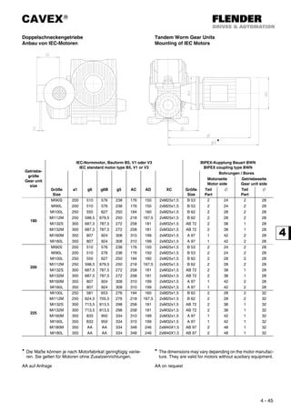


![CAVEX®
4 - 53
Doppelschneckengetriebe
mit Schrumpfscheiben
Tandem Worm Gear Units
with shrink disks
Die Schutzhaube muß gesondert bestellt werden. Guard to be ordered seperately.
Größe
Size
Schrumpfscheibe / Shrink disk d7 d8 d9 d10 f1 G2 G4 l3 l4 l5 l6 l7
Typ(e) T2max
[Nm]
D
63 HSD 36 - 32 630 72 28 30 30 37 1 65 95 160 21 24 25 13
80 HSD 50 - 32 1400 90 39 40 40 48 0,5 80 112 192 25 28 30 13
100 HSD 68 - 32 2200 115 50 55 51 64 1 93 129 222 27 30 30 14
120 HSD 80 - 32 4600 141 60 65 61 75 1 106 144 250 29 32 32 16
140 HSD 90 - 32 6400 155 65 70 66 80 2 118 166 284 35 38 40 16
160 HSD 100 - 32 9700 170 75 80 77 90 2 132 184 316 40 43 45 16
180 HSD 110 - 32 14000 185 85 90 87 100 2 144 202 346 45 48 50 18
200 HSD 125 - 32 21200 215 95 100 97 110 2 155 216 371 48 51 50 19
225 HSD 140 - 32 29800 230 105 110 107 120 2 170 238 408 53 56 60 20
250 HSD 155 - 32 40000 263 115 120 117 130 2 185 257 442 57 60 60 20
280 HSD 165 - 32 51000 290 125 130 127 140 2 200 280 480 63 66 65 22
315 HSD 185 - 32 79000 320 140 150 142 160 2 220 317 537 78 82 80 23
355 HSD 200 - 32 95000 340 155 160 157 170 2 242 340 582 78 82 80
AA
400 HSD 240 - 32 148000 405 175 180 177 190 2 265 385 650 98 102 100
450 HSD 260 - 32 215000 430 200 205 202 215 2 292 425 717 112 116 120
500 HSD 280 - 32 279000 460 220 225 222 235 2 320 467 787 125 130 135
560 HSD 320 - 32 346000 520 240 245 242 255 2 352 507 859 134 140 145
630 HSD 340 - 32 489000 570 270 275 272 285 2 388 558 946 148 155 160
Schutzhaube
Guard
Schrumpfscheibe
Shrink disk
Gleitbuchse
Sliding bush
Anschlußmaße für Welle
Fitting dimensions for shaft](https://image.slidesharecdn.com/flendercavex-170315053907/85/CAVEX-Flender-Siemens-196-320.jpg)


![CAVEX®
4 - 58
Doppelschneckengetriebe Hauptgetriebe
Entlüftung, Ölstand, Ölablaß
Double Worm Gear Units Main Gear Unit
Vent, oil level and oil drain
Größe / Size 63 80 100 120 140/160 180/200 225/250 280/315 355/400 450/500 560/630
X [mm] 60 70 82 95 110 135 160 190 210 240 280
Bei senkrechter Schneckenwelle muß oberhalb des Getriebes
bei M6 bzw. M7 ein Freiraum von der Höhe X vorgesehen
werden.
Position von M6 ist abhängig von der Baulage und Abtriebs-
seite.
For vertical worm shaft arrangement, a space of dimension X
must be left above the gear unit at M6 or M7.
Position M6 is depending on the mounting position and the
side of the output shaft.
Einbaulage / Mounting positions
Bauart Abtrieb auf Seite SU SO SR SL VO VU
Type Output on side ⊗ ⊗ ⊗ ⊗ ⊗ ⊗
CUW
CUA
A A1 B21) B3 B3 B2 A1 B4 M1 A1 A1 M1 B4 M6 B5 M7 M7 B7 M6
B / beiderseits
on both sides
B1 A21)
A3 A3 A2 B1 B1 M1 A4 A4 M1 B1 M6 A7 M7 M7 A5 M6
COW
COA
A B4 B21)
B6 B6 B2 B4 B4 M2/3 A4 A4 M2/3 B4 M6 B5 M7 M7 B7 M6
B / beiderseits
on both sides
A4 A21)
A6 A6 A2 A4 B4 M2/3 A4 A4 M2/3 B4 M6 A7 M7 M7 A5 M6
CFW 2)
CFA
CDA
A A1 B21)
B6 B6 B2 A1 B4 M1 A1 A1 M1 B4 M6 B5 M7 M7 B7 M6
B / beiderseits
on both sides
B1 A21)
A6 A6 A2 B1 B1 M1 A4 A4 M1 B1 M6 A7 M7 M7 A5 M6
Lage der Entlüftung Location of vent
⊗ Lage des Ölstands ⊗ Location of oil level
Lage des Ölablasses Location of oil drain
1)
Bei Größen 63 und 80: B5 statt B2 bzw. A5 statt A2 1)
For sizes 63 and 80: B5 instead of B2, and A5 instead of A2
2)
Bei Bauart CDFW ist der Flansch als Abtrieb definiert. 2)
For type CDFW, the flange is designed as output.
B4
B5 B7
B2
B3
B6
M3
M7
M2
M6
A1 M1 B1
A4
A2
A5 A7
A6
M2
M6
M3
M7
A3
M6 M6](https://image.slidesharecdn.com/flendercavex-170315053907/85/CAVEX-Flender-Siemens-201-320.jpg)
![CAVEX®
4 - 59
Doppelschneckengetriebe Vorschaltgetriebe
Entlüftung, Ölstand, Ölablaß
Double Worm Gear Units Primary Gear Unit
Vent, oil level and oil drain
Größe / Size 100 / 120 140/160 180/200 225/250 280/315 355/400 450/500 560/630
X [mm] 60 70 82 95 110 135 160 190
Bei senkrechter Schneckenwelle muß oberhalb des Getriebes
bei M6 bzw. M7 ein Freiraum von der Höhe X vorgesehen wer-
den.
Position von M6 ist abhängig von der Baulage und Abtriebs-
seite.
For vertical worm shaft arrangement, a space of dimension X
must be left above the gear unit at M6 or M7.
Position M6 is ....
an der Vorschaltstufe / on primary gear stage
Einbaulage (Hauptstufe) / Mounting position (main gear stage)
Antriebswelle
in Stellung
SU SO SR SL VO VU
Input shaft
in position
⊗ ⊗ ⊗ ⊗ 3)
⊗ 3)
⊗
a A6 A2 B1 B1 A21)
A6 M7 A5 M6 M6 A7 M7 A4 M1 B1 B1 M1 A4
b B6 B2 A1 A1 B21)
B6 M6 B5 M7 M7 B7 M6 B4 M1 A1 A1 M1 B4
c A1 B21)
B6 B6 B2 A1 M7 B7 M6 M6 B5 M7 B4 M1 A1 A1 M1 B4
d B1 A21)
A6 A6 A2 B1 M6 A7 M7 M7 A5 M6 A4 M1 B1 B1 M1 A4
e M6 A7 M7 M7 A5 M6 A6 A2 B1 B1 A21)
A6 A4 M1 B1 B1 M1 A4
f M7 B7 M6 M6^ B5 M7 B6 B2 A1 A1 B21)
B6 B4 M1 A1 A1 M1 B4
g M6 B5 M7 M7 B7 M6 A1 B21)
B6 B6 B2 A1 B4 M1 A1 A1 M1 B4
h M7 A5 M6 M6 A7 M7 B1 A21)
A6 A6 A2 B1 A4 M1 B1 B1 M1 A4
Lage der Entlüftung Location of vent
⊗ Lage des Ölstands ⊗ Location of oil level
Lage des Ölablasses Location of oil drain
1) Bei Größen 100 - 160: B5 statt B2 bzw. A5 statt A2 1) For sizes 100 - 160: B5 instead of B2, and A5 instead of A2
Bei den Hauptstufen geltendie Angaben für einstufige Bauar-
ten mit den gleichen 2 Endbuchstaben, siehe Seite 2 - 53.
For the main gear stages, the data for single stage types with
the same two ending letters apply, see page 2 - 53.
B4
B5 B7
B2
B3
B6
M3
M7
M2
M6
A1 M1 B1
A4
A2
A5 A7
A6
M2
M6
M3
M7
A3
M6 M6](https://image.slidesharecdn.com/flendercavex-170315053907/85/CAVEX-Flender-Siemens-202-320.jpg)
![CAVEX®
4 - 60
Doppelschneckengetriebe
Durchschnittliche Ölmengen und Gewichte
Double Worm Gear Units
Average Oil quantities an Weights
Größe
Size
Ölmengen der Vorschaltstufe
oil quantities of the primary gear stage
[ l ]
Gewichte von Vorschalt- und Hauptstufe ohne Öl
Weights of primary and main gear stage without oil
[kg]
Einbaulage / Mouting position Bauart / Type
SU SO SR SL VO/VU CD.W CD.A
a/b c/d e-h a/b c/d e-h a/b c/d e-h a/b c/d e-h a-h
100
0,7 0,6 1 0,6 0,7 1 1 0,7 0,6 1 0,6 0,7 0,6
57 55
120 80 77
140
1,6 1,2 2 1,2 1,6 2 2 1,6 1,2 2 1,2 1,6 1,1
115 110
160 150 145
180
3 1,3 3,8 1,3 3 3,8 3,8 3 1,3 3,8 1,3 3 2
210 200
200 260 250
225
5 2 6,5 2 5 6,5 6,5 5 2 6,5 2 5 3,5
350 330
250 440 420
280 8 3 10 3 8 10 10 8 3 10 3 8 5,5 600 570
315 11,5 4,5 15 4,5 11,5 15 15 11,5 4,5 15 4,5 11,5 8 810 770
355 16 5,5 20 5,5 16 20 20 16 54,5 20 5,5 16 11 1180 1130
400 22 7,5 27 7,5 22 27 27 22 7,5 27 7,5 22 15 1600 1540
450 29 10 36 10 29 36 36 29 10 36 10 29 20 2240 2170
500 40 13 47 13 40 47 47 40 13 47 13 40 26 3040 2960
560 54 15 62 15 54 62 62 54 15 62 15 54 33 4170 4070
630 72 20 82 20 72 82 82 72 20 82 20 72 47 5630 5510](https://image.slidesharecdn.com/flendercavex-170315053907/85/CAVEX-Flender-Siemens-203-320.jpg)


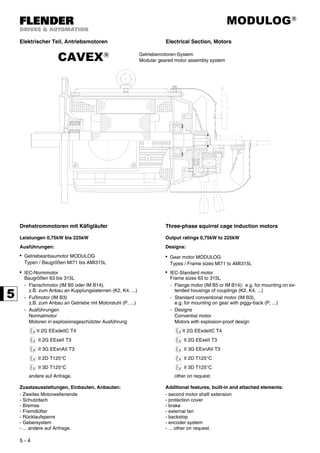


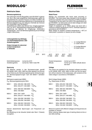


![MODULOG®
5 - 14
Drehzahl Speed
Die in den Datenblättern angegebenen Bemessungsdrehzah-
len gelten bei 50Hz bzw. 60Hz. Die Bemessungsdrehzahl ent-
spricht der Synchrondrehzahl abzüglich Schlupfdrehzahl.
The rated speeds shown in the data sheets are valid for 50Hz
and 60Hz. The rated speed equals synchronous speed less
slip speed.
Es ergeben sich in Abhängigkeit von der Polzahl und den Netz-
frequenzen 50Hz und 60Hz folgende Synchrondrehzahlen:
The following speeds result from the number of poles and the
mains frequencies of 50Hz and 60Hz:
Polzahl des
Motors
Synchrondrehzahl
bei Netzfrequenz
No. of
poles
Synchronous speed
at mains frequencies
n (50Hz)
[min-1
]
n (60Hz)
[min-1
]
n (50Hz)
[min-1
]
n (60Hz)
[min-1
]
2 3000 3600 2 3000 3600
4 1500 1800 4 1500 1800
6 1000 1200 6 1000 1200
8 750 900 8 750 900
10 600 720 10 600 720
12 500 600 12 500 600
16 375 450 16 375 450
Bemessungstrom Rated current
In den Leistungstabellen sind die Bemessungsströme für eine
Bemessungsspannung von 400V angegeben. Bei anderen
Spannungen und entsprechender Wicklungsauslegung
ändern sich die Bemessungsströme im umgekehrten Verhält-
nis wie die Spannungen:
The rated currents shown in the tables are valid for nominal
voltage 400V. The rated currents of motors wound for different
voltages vary in inverse proportion to the voltages:
daraus folgt: From this it follows that:
Wirkungsgrad, Leistungsfaktor Efficiency, Power factor
Die in den Datenblättern dieses Kataloges angegebenen
Leistungsfaktoren und Wirkungsgrade beziehen sich auf Be-
messungsleistung / Vollast bei 50Hz und 60Hz.
Werte für exakt bekannte Betriebsbedingungen (Betriebs-
spannung, Teillast) auf Anfrage.
Wirkungsgradklassen der CEMEP/EU-Vereinbarung für Netz-
betrieb bei 50Hz.
The values for power factors and efficiencies shown in the
data-sheets of this catalogue are applicable for rated power/
full load at 50Hz and 60Hz.
Values for exactly known operating conditions (operating
voltage, partly load) on request.
Efficiency level class to the CEMEP/EC-Agreement for mains
operation at 50Hz.
ηN [%] ≥
PN 2 - polig / pole 4 - polig / pole
eff2 eff1 eff2 eff1
[kW] [-] [-] [-] [-]
1,1 76,2 82,8 76,2 83,8
1,5 78,5 84,1 78,5 85,0
2,2 81,0 85,6 81,0 86,4
3,0 82,6 86,7 82,6 87,4
4,0 84,2 87,6 84,2 88,3
5,5 85,7 88,6 85,7 89,2
7,5 87,0 89,5 87,0 90,1
11 88,4 90,5 88,4 91,0
15 89,4 91,3 89,4 91,8
18,5 90,0 91,8 90,0 92,2
22 90,5 92,2 90,5 92,6
30 91,4 92,9 91,4 93,2
37 92,0 93,3 92,0 93,6
45 92,5 93,7 92,5 93,9
55 93,6 94,0 93,0 94,2
75 93,6 94,6 93,6 94,7
90 93,9 95,0 93,9 95,0
U
U′
------
I′
I
---=
U
U′
------
I′
I
---=
I′
U I⋅
U′
----------= I′
U I⋅
U′
----------=](https://image.slidesharecdn.com/flendercavex-170315053907/85/CAVEX-Flender-Siemens-219-320.jpg)


![MODULOG®
5 - 17
Stillstandsheizung Anti-condensation heating
Auf Wunsch gegen Mehrpreis. Available as optional extra.
Zum Schutz gegen Kondenswasser im Motorinneren können
die Motoren auf Kundenwunsch mit einer Stillstandsheizung
ausgerüstet werden. Normale Anschlußspannung siehe
Tabelle. Andere Anschlußspannungen auf Anfrage. Die Still-
standsheizung darf während des Betriebs nicht eingeschaltet
sein.
Wahlweise ist es möglich, bei Anschluß einer Spannung von
etwa 5-10% der Motornennspannung an den Klemmen U1 und
V1 (einphasig) die Ständerwicklung ausreichend zu erwärmen.
As protection against condensed water inside the motors, the-
se can be equipped with a space heater, if requested by the
customer. The standard supply voltages are shown in the
table. Other supply voltages on request. The space heater
must never be switched on during operation of the motor.
Alternatively it is possible to keep the stator winding warm by
applying a single-phase voltage of about 5-10% of the rated
motor voltage to terminals U1 and V1.
Motor Anschlußspannung / Supply voltage
[V]
Heizleistung / Filament wattage
[W]
MI71 230
28
MI80 230
MI90S/L 230
MI100L 230
MI112M 230
29
MI132S/M 230
MI160M/L 230
44MI180M/L 230
MI200L 230
AMI225S/M 230 65
AMI250M 230 65
AMI280S/M 230 65
AMI315S/M/L 230 99
Anschlußbeispiel: Connection sample:
HE1 (H1) - HE2 (H2):
UStandard = 230 VAC
50/60Hz
U2(T4) V2(T5 ) W2(T6)
TP1(P1) U1(T1) V1(T2) W1(T3) TP2(P2) HE1(H1) HE2(H2)](https://image.slidesharecdn.com/flendercavex-170315053907/85/CAVEX-Flender-Siemens-222-320.jpg)


![MODULOG®
5 - 20
Lüfter Fans
Die Lüfter sind für beide Drehrichtungen geeignet. The fans are suitable for both rotational directions.
Kühlart: IC 411 (EN 60034-6/IEC 60034-6) Cooling type: IC 411 (EN 60034-6/IEC 60034-6)
Standardwerkstoff:
Glasfaserverstärkter Kunststoff
Standard materials:
Glass-fibre reinforced plastic
Schwungradlüfter High inertia fans
Für Bremsmotoren der Baugröße MI71 bis MI132S/M stehen
auf Anfrage Schwungradlüfter als Zusatzschwungmasse aus
Grauguß zur Verfügung. Diese Lüfter sind feinausgewuchtet
(DIN ISO 1940), so daß die Laufruhe der Motoren nicht beein-
trächtigt wird.
EinsatzfällesindtypischerweiseAntriebevonFahrwerken,För-
derzeugen u. ä. (siehe dazu auch Katalog "EHBN01"), bzw. all-
gemein zur Unterstützung eines Sanftanlaufes und/oder
sanfter Bremsung.
ZurAuswahlderrichtigenMotorauslegung(ggfs.Siluminläufer,
angepaßte Wicklung etc.) erbitten wir Rückfrage.
For brake motors of size MI71 to MI132S/M, standard cast iron
high inertia fans are available on request to serve as an addi-
tional moment of inertia.
These fans are finely dynamically balanced (DIN ISO 1940),
so that smooth running of the motors is not impaired. Typical
applications are in running gear and material handling gear
drives, etc. (see also catalogue "EHBN01"), or generally for
supporting smooth starting and/or braking.
Please inquire regarding the choice of the correct motor design
(Silumin rotor, adapted winding, etc.).
Motor Schwungmasse / Moment of inertia
Läufer (4 polig) / Rotor (4 pole) Schwungradlüfter / High inertia fan
Jrotor [kgm2] Jlüfter [kgm2] mlüfter [kg]
MI71B4/C4/S4 0,00076
0,00171 1,38MI71M4 0,00099
MI71MB4 0,00111
MI80S4 0,00173
0,00279 1,75
MI80M4 0,00210
MI90S4 0,00252
0,00540 2,55
MI90L4 0,00332
MI100L4 0,00428
0,1160 3,3
MI100LB4 0,00501
MI112MB4 0,00979 0,0230 5,3
MI132SB4 0,02217
0,0562 9,1MI132M4 0,02869
MI132MB4 0,02869](https://image.slidesharecdn.com/flendercavex-170315053907/85/CAVEX-Flender-Siemens-225-320.jpg)

![MODULOG®
5 - 22
Motor Klemmkastenlage
Location of terminal box
Normallage
Standard location
Winkel α
Angle α
[°]
Lage der Motorschrauben
Position of motor-studs
y ᔥ
[mm]
MI71
MI80
1
2
3
4
1A 0
90
180
270
b 94
MI90S/L
MI100L
MI112M
1
2
3
4
1A 0
90
180
270
d 110
MI132S/M
MI160M/L
1
2
3
4
1A 0
90
180
270
d 127
MI180M/L
MI200L
1
2
3
4
1A 0
90
180
270
d 147
AMI225S/M
AMI250M
AMI280S/M
1
2
3
4
1A 0
90
180
270
auf Anfrage / on request
AMI315S/M/L 1
2
3
4
1A 0
90
180
270
b d](https://image.slidesharecdn.com/flendercavex-170315053907/85/CAVEX-Flender-Siemens-227-320.jpg)


![MODULOG®
5 - 27
Lager Bearings
Bei den Motoren werden auf der A- und B-Seite (AS, BS)
Wälzlager eingesetzt.
Ball bearings are fitted on the drive and nondrive ends (DE,
NE) of the motors.
Die Lager des Baugrößenbereiches MI71 bis AMI280S/M ha-
ben Dauerschmierung. Der beim Einbau im Werk eingebrach-
te Schmierfettvorrat reicht erfahrungsgemäß für mehrere
Jahre aus.
The bearings of the size range MI71 to AMI280S/M are per-
manently lubricated. The stock of lubricating grease supplied
during installation in the factory generally lasts for several
years.
Die heutige Qualität der Wälzlagerschmierfette ermöglicht
Dauerschmierung für eine Lagerlebensdauer von mindestens
22000 Betriebsstunden bei 1500/min und normalen Betriebs-
bedingungen.
Der Lageraufbau wird einfacher und der Motor nahezu war-
tungsfrei. Dadurch werden Lagerschäden vermieden, die von
Wartungsfehlern wie Überschreitung der Schmierfrist oder
Verwendung einer anderen, unverträglichen Fettsorte ausge-
hen können.
The quality of roller bearing greases today allows permanent
lubrication for a bearing service life of at least 22000 operating
hours at 1500/min under normal operating conditions.
The bearing design is simplified and the motor is virtually
maintenance-free. This avoids damage to the bearings due to
maintenance errors such as exceeding the lubrication interval
or using a different, incompatible grease type.
Fettstandzeit bei Bemessungsdrehzahl nN
in Betriebsstunden [h]
Grease lifetime at rated speed nN
in operating hours [h]
Motor Waagrechte Bauformen (IM B.)
Horizontal operating positions (IM B.)
Senkrechte Bauformen (IM V.)
Vertical operating positions (IM V.)
nN [min-1] nN [min-1]
3600 3000 1800 1500 1200 ≤1000 3600 3000 1800 1500 1200 ≤1000
MI71
33000
33000
33000 33000 33000 33000
24000
33000
33000
33000
33000
33000
MI80
24000MI90S/L
MI100L
24000
17000
MI112M
17000
24000
MI132S/M
24000 12000 24000
MI160M/L
17000MI180M/L
12000 24000
MI200L
AMI225S/M
auf Anfrage / on request
AMI250M
AMI280S/M
AMI315S/M/L](https://image.slidesharecdn.com/flendercavex-170315053907/85/CAVEX-Flender-Siemens-232-320.jpg)
![MODULOG®
5 - 28
Schmierung der Wälzlager Greasing of the bearings
Die angegebenen Fettstandzeiten (Lagerlebensdauer) gelten
für eine Umgebungstemperatur von max. 40°C *.
Bei einer Umgebungstemperatur von 25°C ist die doppel-
te Fettstandzeit zu erwarten.
The specified life of the grease (bearing service life) is valid for
an ambient temperature of 40°C maximum *.
At an ambient temperature of 25°C, the life of the grease
can be doubled.
Wälzlagerschmierstoffe für Motoren Lubricants for roller bearings of motors
Bei
Umgebungstemperatur*
At ambient temperature*
[°C]
Schmierstoffbezeichnung / Name of the lubricant
-30 ... +60 Aralub
HL3, HL2
Energrease
LS3, LS2
Longtime PD2
TRIBOL
4020/220-2
Glissando
30, 20
Beacon 3
Renolit
FWA160,
FWA220
Centroplex
GLP402
Mobilux 3, 2
Alvania
R3, R2
Wiloub
LFK2
FLENDER TÜBINGEN Artikel-Nr. / Part.-No.: 050256
-30 ... +100 Energrease
HTB2
TRIBOL
4747
Unitemp 2
COSTRAC
AK 302
Mobiltemp
SHC 100
FLENDER TÜBINGEN Artikel-Nr. / Part.-No.: 984619
Weitere Sorten auf Anfrage. Other brands on request.
* Achtung * Attention
In EN 60034-1 sind folgende Umgebungstemperaturen bei
Bemessungsleistung für den Normalbetrieb vorgesehen:
In EN 60034-1 following ambient temperatures at power rating
are provided for normal operation:
< 0,6 kW 0°C ... 40°C
≥ 0,6 kW -15°C...40°C
< 0,6 kW 0°C ... 40°C
≥ 0,6 kW -15°C...40°C
Bei höheren oder tieferen Umgebungstemperaturen erbitten
wir Rücksprache.
For higher or lower ambient temperatures please contact our
agency.](https://image.slidesharecdn.com/flendercavex-170315053907/85/CAVEX-Flender-Siemens-233-320.jpg)


![MODULOG®
5 - 31
Elektromotoren Typen AMI, MI
Betriebsdaten
Electric Motors types AMI, MI
Data
Legende / Erläuterungen siehe Seite 5 - 30 Legend / explanations see page 5 - 30
Drehstrommotoren
2 polig
Three phase squirrel cage motor
2 pole
3000 min-1
/ 50Hz 3000 min-1
/ 50Hz
Synchrone Drehzahl
220...240/380...420V ∆/Y 50Hz *
oder 380...420/655...725 V ∆ 50Hz *
Synchronous Speed
220...240/380...420V ∆/Y 50Hz *
or 380...420/655...725 V ∆ 50Hz *
IEC Typ(e) PN
[kW]
nN
[min-1
]
IN
(400V)
[A]
cos ϕ
[-]
η
(1/1)
[%]
η
(3/4)
[%]
eff
[-]
IA / IN
[-]
TA / TN
[-]
TK / TN
[-]
THm / TN
[-]
Jmot
[kgm2
]
mmot ca.
[kg]
63 MI71B2 0,18 2840 0,47 0,83 67 67 - 5,5 2,5 2,8 2,3 0,00032 7,6
MI71C2 0,25 2840 0,65 0,78 71 69,3 - 5,5 2,7 2,8 2,4 0,00032 7,6
71 MI71S2 0,37 2800 0,93 0,84 68 67 - 5 2,3 2,5 1,9 0,00032 7,6
MI71M2 0,55 2820 1,32 0,85 71 69 - 5,5 2,6 2,75 2,2 0,00040 8,4
80 MI80S2 0,75 2840 1,7 0,86 74 72 - 5,2 2,3 2,6 2,2 0,00093 10,5
MI80M2 1,1 2850 2,4 0,86 77,3 75 2 6 2,3 2,8 2,24 0,00114 11,5
90S MI90S2 1,5 2850 3,2 0,85 80 79,1 2 5,9 2,3 2,9 2,45 0,00138 14,8
90L MI90L2 2,2 2860 4,6 0,85 82,5 81,5 2 6,1 2,5 3,1 2,43 0,00171 16,7
100L MI100L2 3 2880 6 0,86 84 82,5 2 6,25 2,85 3,6 2,76 0,00264 22,0
112M MI112M2 4 2890 7,5 0,9 85,5 84,6 2 6,4 2,8 3,4 2,2 0,00438 30,0
132S MI132S2 5,5 2890 10,30 0,89 86,5 86 2 6,6 2,7 3,6 2,18 0,01228 49,0
MI132SB2 7,5 2900 14 0,89 87,7 86,9 2 6,8 2,8 3,6 2,26 0,01529 56,0
160M MI160M2 11 2900 19,6 0,9 90,4 89,6 2 7 2,6 3,5 2,3 0,02932 83,0
MI160MB2 15 2910 26,5 0,9 90,8 89,9 2 7 2,7 3,5 2,4 0,03606 95,0
160L MI160L2 18,5 2920 32,2 0,91 91,2 90,7 2 7 2,7 3,5 2,4 0,04364 108,0
180M MI180M2E 22 2945 37,5 0,91 93,3
AA
1 7,5 2,6 3,6
AA200L MI200L2E 30 2950 52,5 0,88 93,5 1 7,6 2,1 3,6
MI200LB2E 37 2955 64,9 0,88 94,0 1 7,7 2,5 4,2
225M AMI225MP2E 45 2950 82 0,88 94,2 94,1 1 7,9 2,5 2,9 2,2 0,270 315
250M AMI250MP2E 55 2955 99 0,89 94,3 94,2 1 7,7 2,4 3 2,2 0,424 410
280S AMI280SV2E 75 2975 132 0,9 94,9 94,4 1 7,5 1,9 3,2 2 0,816 560
280M AMI280MV2E 90 2975 161 0,89 95,2 94,8 1 7,5 1,9 3,2 2 0,957 620
315S AMI315SY2 110 2980 200 0,85 95 94,5 - 7,7 2,2 3,3 2 1,00 650
315M AMI315MZ2 132 2980 235 0,88 95,5 95,2 - 6,8 2,4 2,6 1,7 1,20 810
315L AMI315LY2 160 2980 280 0,9 95,9 95,7 - 7,2 2,5 2,6 1,7 1,40 900
AMI315LZ2 200 2980 347 0,89 96,3 96,1 - 7,8 2,7 2,7 1,8 1,60 1000
* Andere Spannungen oder spannungsumschaltbare Ausführungen
sind möglich (Mehrpreis).
* Other voltages or types with changeable voltages are possible
(extra charge).
AA auf Anfrage AA on request](https://image.slidesharecdn.com/flendercavex-170315053907/85/CAVEX-Flender-Siemens-236-320.jpg)
![MODULOG®
5 - 32
Elektromotoren Typen AMI, MI
Betriebsdaten
Electric Motors types AMI, MI
Data
Legende / Erläuterungen siehe Seite 5 - 30 Legend / explanations see page 5 - 30
Drehstrommotoren
2 polig
Three phase squirrel cage motor
2 pole
3600 min-1
/ 60Hz 3600 min-1
/ 60Hz
Synchrone Drehzahl
220 ... 240 / 380 ... 420 V ∆/Y 60Hz *
oder 380 ... 420 / 655 ... 725 V ∆/Y 60Hz *
Synchronous Speed
220 ... 240 / 380 ... 420 V ∆/Y 60Hz *
or 380 ... 420 / 655 ... 725 V ∆/Y 60Hz *
IEC Typ(e) PN
[kW]
nN
[min-1
]
IN
(400V)
[A]
cos ϕ
[-]
η
[%]
IA / IN
[-]
TA / TN
[-]
TK/ TN
[-]
THm / TN
[-]
Jmot
[kgm2
]
mmot ca.
[kg]
63 MI71B2 0,18 3400 0,43 0,86 70 4,57 2,08 2,32 1,91 0,00032 7,6
MI71C2 0,25 3400 0,61 0,81 72,7 4,57 2,24 2,32 1,99 0,00032 7,6
71 MI71S2 0,37 3350 0,9 0,87 68,5 4,15 1,91 2,08 1,58 0,00032 7,6
MI71M2 0,55 3370 1,27 0,87 72,3 4,57 2,16 2,28 1,83 0,00040 8,4
80 MI80S2 0,75 3400 1,65 0,88 74,3 4,32 1,91 2,16 1,83 0,00093 10,5
MI80M2 1,1 3410 2,35 0,87 77,5 4,98 1,91 2,32 1,86 0,00114 11,5
90S MI90S2 1,5 3410 3,1 0,88 79,6 4,9 1,91 2,41 2,03 0,00138 14,8
90L MI90L2 2,2 3410 4,35 0,89 81,9 5,06 2,08 2,57 2,02 0,00171 16,7
100L MI100L2 3 3445 5,75 0,9 83,4 5,19 2,37 2,99 2,29 0,00264 22,0
112M MI112M2 4 3460 7,4 0,92 85 5,31 2,32 2,82 1,83 0,00438 30,0
132S MI132S2 5,5 3460 9,95 0,93 85,8 5,48 2,24 2,99 1,81 0,01228 49,0
MI132SB2 7,5 3475 13,55 0,92 86,9 5,64 2,32 2,99 1,88 0,01529 56,0
160M MI160M2 11 3490 19,35 0,91 90,9 6,2 2,2 3 1,93 0,02932 83,0
MI160MB2 15 3500 25,95 0,91 91,3 6,1 2,2 3 2,01 0,03606 95,0
160L MI160L2 18,5 3500 31,43 0,92 91,6 6,2 2,3 3,1 2 0,04364 108,0
180M MI180M2E 22 3545
auf Anfrage / on request200L MI200L2E 30 3550
MI200LB2E 37 3555
225M AMI225MP2E 26 3555 42 0,90 89 7,7 2,4 AA 1,6 0,150 160
250M AMI250MP2E 55 3545 99 0,90 94,5 6,6 2,1 2,5 1,8 0,424 410
280S AMI280SV2E 75 3570 130 0,91 94,5 6,5 1,6 2,6 1,6 0,816 560
280M AMI280MV2E 90 3575 153 0,91 95,1 6,6 1,6 2,6 1,6 0,957 620
315S AMI315SY2 110 3575 189 0,91 95 7,2 1,8 2,8 1,7 1,00 650
315M AMI315MZ2 132 3575 224 0,9 95 6 1,7 2,2 1,4 1,20 810
315L AMI315LY2 160 3575 275 0,91 95,5 6,2 2 2,3 1,4 1,40 900
AMI315LZ2 200 3575 340 0,91 96 6,7 2,2 2,2 1,4 1,60 1000](https://image.slidesharecdn.com/flendercavex-170315053907/85/CAVEX-Flender-Siemens-237-320.jpg)
![MODULOG®
5 - 33
Elektromotoren Typen AMI, MI
Betriebsdaten
Electric Motors types AMI, MI
Data
Legende / Erläuterungen siehe Seite 5 - 30 Legend / explanations see page 5 - 30
Drehstrommotoren
2 polig
Three phase squirrel cage motor
2 pole
3600 min-1
/ 60Hz 3600 min-1
/ 60Hz
Synchrone Drehzahl
254...277/440...480V ∆/Y 60Hz *
oder 440...480 V ∆ 60Hz *
Synchronous Speed
254...277/480...480V ∆/Y 60Hz *
or 440...480 V ∆ 60Hz *
IEC Typ(e) PN
[kW]
nN
[min-1
]
IN
(460V)
[A]
cos ϕ
[-]
η
[%]
IA / IN
[-]
TA / TN
[-]
TK/ TN
[-]
THm / TN
[-]
Jmot
[kgm2
]
mmot ca.
[kg]
63 MI71B2 0,22 3405 0,48 0,83 69 5,25 2,74 3,07 2,52 0,00032 7,6
MI71C2 0,3 3405 0,65 0,79 73 5,25 2,96 3,07 2,63 0,00032 7,6
71 MI71S2 0,45 3360 0,94 0,87 69,3 4,77 2,52 2,74 2,08 0,00032 7,6
MI71M2 0,66 3380 1,34 0,86 72 5,25 2,85 3,02 2,41 0,00040 8,4
80 MI80S2 0,9 3410 1,72 0,88 75 4,96 2,52 2,85 2,41 0,00093 10,5
MI80M2 1,3 3420 2,43 0,87 77,4 5,72 2,52 3,07 2,46 0,00114 11,5
90S MI90S2 1,8 3420 3,27 0,86 80,3 5,63 2,52 3,18 2,69 0,00138 14,8
90L MI90L2 2,6 3420 4,57 0,87 82,1 5,82 2,74 3,4 2,67 0,00171 16,7
100L MI100L2 3,6 3455 6,05 0,89 83,7 5,96 3,13 3,95 3,03 0,00264 22,0
112M MI112M2 4,8 3470 7,7 0,91 85,7 6,11 3,07 3,73 2,41 0,00438 30,0
132S MI132S2 6,6 3470 10,65 0,91 86,7 6,3 2,96 3,95 2,39 0,01228 49,0
MI132SB2 9 3480 14,47 0,89 88 6,49 3,07 3,95 2,48 0,01529 56,0
160M MI160M2 13 3480 19,5 0,9 91,3 6,4 2,7 3,6 2,4 0,02932 83,0
MI160MB2 18 3490 26,8 0,92 91,9 6,5 2,8 3,5 2,45 0,03606 95,0
160L MI160L2 22 3490 32,4 0,92 92,2 6,5 2,8 3,6 2,44 0,04364 108,0
180M MI180M2E 26 3545
auf Anfrage / on request200L MI200L2E 36 3550
MI200LB2E 66 3555
225M AMI225MP2E 52 3545 81 0,90 94,5 7,9 2,6 2,8 2,2 0,270 315
250M AMI250MP2E 63 3550 97 0,90 94,7 7,9 2,5 3,1 2,2 0,424 410
280S AMI280SV2E 84 3575 129 0,90 94,7 7,7 2,0 3,2 2 0,816 560
280M AMI280MV2E 103 3580 154 0,89 95,2 7,7 2,0 3,2 2 0,957 620
315S AMI315SY2 122 3580 189 0,87 95 8,2 2,4 3,5 2,1 1,00 650
315M AMI315MZ2 148 3580 217 0,89 95,3 7 2,4 2,6 1,7 1,20 810
315L AMI315LY2 180 3580 270 0,9 95,8 7,4 2,5 2,6 1,7 1,40 900
AMI315LZ2 225 3580 336 0,89 96,2 8 2,7 2,7 1,8 1,60 1000
* Andere Spannungen oder spannungsumschaltbare Ausführungen
sind möglich (Mehrpreis).
* Other voltages or types with changeable voltages are possible
(extra charge).](https://image.slidesharecdn.com/flendercavex-170315053907/85/CAVEX-Flender-Siemens-238-320.jpg)
![MODULOG®
5 - 34
Elektromotoren Typen AMI, MI
Betriebsdaten
Electric Motors types AMI, MI
Data
Legende / Erläuterungen siehe Seite 5 - 30 Legend / explanations see page 5 - 30
Drehstrommotoren
2 polig
Wirkungsgradklasse eff1
Three phase squirrel cage motor
2 pole
Efficiency level class eff1
3000 min-1 / 50Hz 3000 min-1 / 50Hz
Synchrone Drehzahl
220 ... 240 / 380 ... 420 V ∆/Y 50Hz
oder 380 ... 420 / 655 ... 725 V ∆/Y 50Hz
Synchronous Speed
220 ... 240 / 380 ... 420 V ∆/Y 50Hz
or 380 ... 420 / 655 ... 725 V ∆/Y 50Hz
IEC Typ(e) PN
[kW]
nN
[min-1
]
IN
(400V)
[A]
cos ϕ
[-]
η
(1/1)
[%]
η
(3/4)
[%]
eff
[-]
IA / IN
[-]
TA / TN
[-]
TK / TN
[-]
THm / TN
[-]
Jmot
[kgm2
]
mmot
[kg]
80 MI80MP2E 1,1 2880 2,4 0,81 82,9 82,2 1 8,2 4 4,4 4,2 0,00155 14,0
90L MI90LB2E 1,5 2900 3,1 0,83 85,2 84,5 1 8,3 3,7 4,4 3,75 0,00191 18,5
MI90LP2E 2,2 2900 4,4 0,84 85,7 85 1 8,4 3,8 4,5 3,65 0,00191 18,3
100L MI100LP2E 3 2920 5,8 0,86 86,8 85,9 1 9,5 4,3 5 4,15 0,00358 27,0
112M MI112MB2E 4 2890 7,5 0,88 87,6 86,5 1 7,5 3,1 3,7 2,6 0,00534 35,0
132S MI132SB2E 5,5 2920 10,1 0,89 88,6 88,3 1 9 3,5 3,9 3,1 0,01529 58,0
132M MI132MB2E 7,5 2920 13,5 0,90 89,5 89 1 9 3,6 4 3,3 0,01701 62,0
160M MI160M2E 11 2930 19,8 0,88 90,8 90,3 1 8 2,8 3,5 2,56 0,02932 85,0
MI160MB2E 15 2940 26,2 0,90 92 91,5 1 8,8 3,5 4 3,1 0,03606 97,0
160L MI160L2E 18,5 2930 32 0,91 92,2 92,5 1 8,2 3,3 3,9 3,0 0,04364 109,0](https://image.slidesharecdn.com/flendercavex-170315053907/85/CAVEX-Flender-Siemens-239-320.jpg)
![MODULOG®
5 - 35
Elektromotoren Typen AMI, MI
Betriebsdaten
Electric Motors types AMI, MI
Data
Legende / Erläuterungen siehe Seite 5 - 30 Legend / explanations see page 5 - 30
Drehstrommotoren
2 polig
Basis: Wirkungsgradklasse eff1
Three phase squirrel cage motor
2 pole
Basis: Efficiency level class eff1
3600 min-1 / 60Hz 3600 min-1 / 60Hz
Synchrone Drehzahl
220 ... 240 / 380 ... 420 V ∆/Y 60Hz
oder 380 ... 420 / 655 ... 725 V ∆/Y 60Hz
Synchronous Speed
220 ... 240 / 380 ... 420 V ∆/Y 60Hz
or 380 ... 420 / 655 ... 725 V ∆/Y 60Hz
IEC Typ(e) PN
[kW]
nN
[min-1
]
IN
(400V)
[A]
cos ϕ
[-]
η
(1/1)
[%]
IA / IN
[-]
TA / TN
[-]
TK / TN
[-]
THm / TN
[-]
Jmot
[kgm2
]
mmot
[kg]
80 MI80MP2E 1,1 3445 2,3 0,84 82,5 6,81 3,32 3,65 3,49 0,00155 14,0
90L MI90LB2E 1,5 3770 2,93 0,86 86 6,89 3,07 3,65 3,11 0,00191 18,5
MI90LP2E 2,2 3770 4,22 0,87 86,5 6,97 3,15 3,74 3,03 0,00191 18,3
100L MI100LP2E 3 3495 5,65 0,88 87,5 7,89 3,57 4,15 3,44 0,00358 27,0
112M MI112MB2E 4 3460 7,25 0,9 88,5 6,23 2,57 3,07 2,16 0,00534 35,0
132S MI132SB2E 5,5 3524 9,96 0,89 88,9 7,47 2,91 3,24 2,57 0,01529 58,0
132M MI132MB2E 7,5 3517 13,1 0,93 89,9 7,47 2,99 3,32 2,74 0,01701 62,0
160M MI160M2E 11 3496 19,6 0,89 91 6,64 2,32 2,91 2,12 0,02932 85,0
MI160MB2E 15 3509 25,8 0,91 92,1 7,3 2,91 3,32 2,57 0,03606 97,0
160L MI160L2E 18,5 3509 31,8 0,91 92 6,81 2,74 3,24 2,49 0,04364 109,0](https://image.slidesharecdn.com/flendercavex-170315053907/85/CAVEX-Flender-Siemens-240-320.jpg)
![MODULOG®
5 - 36
Elektromotoren Typen AMI, MI
Betriebsdaten
Electric Motors types AMI, MI
Data
Legende / Erläuterungen siehe Seite 5 - 30 Legend / explanations see page 5 - 30
Drehstrommotoren
2 polig
Basis: Wirkungsgradklasse eff1
Three phase squirrel cage motor
2 pole
Basis: Efficiency level class eff1
3600 min-1 / 60Hz 3600 min-1 / 60Hz
Synchrone Drehzahl
254...277/440...480V ∆/Y 60Hz
oder 440...480 V ∆ 60Hz
Synchronous Speed
254...277/480...480V ∆/Y 60Hz
or 440...480 V ∆ 60Hz
IEC Typ(e) PN
[kW]
nN
[min-1
]
IN
(460V)
[A]
cos ϕ
[-]
η
(1/1)
[%]
IA / IN
[-]
TA / TN
[-]
TK / TN
[-]
THm / TN
[-]
Jmot
[kgm2
]
mmot
[kg]
80 MI80MP2E 1,3 3455 2,4 0,82 83 7,82 4,39 4,83 4,61 0,00155 14,0
90L MI90LB2E 1,8 3780 3,1 0,84 86,7 7,92 4,06 4,83 4,11 0,00191 18,5
MI90LP2E 2,6 3780 4,4 0,85 87,2 8,01 4,17 4,94 4,0 0,00191 18,3
100L MI100LP2E 3,6 3505 5,9 0,87 88 9,06 4,72 5,49 4,55 0,00358 27,0
112M MI112MB2E 4,8 3470 7,6 0,89 89 7,16 3,4 4,06 2,85 0,00534 35,0
132S MI132SB2E 6,6 3532 10,28 0,9 89,3 8,59 3,84 4,28 3,4 0,01529 58,0
132M MI132MB2E 9 3525 13,69 0,92 90,2 8,59 3,95 4,39 3,62 0,01701 62,0
160M MI160M2E 13 3509 20,2 0,89 91,2 7,63 3,07 3,84 2,81 0,02932 85,0
MI160MB2E 18 3514 26,5 0,92 92,3 8,4 3,84 4,39 3,4 0,03606 97,0
160L MI160L2E 22 3511 32,6 0,92 92,5 7,82 3,62 4,28 3,29 0,04364 109,0](https://image.slidesharecdn.com/flendercavex-170315053907/85/CAVEX-Flender-Siemens-241-320.jpg)
![MODULOG®
5 - 37
Elektromotoren Typen AMI, MI
Betriebsdaten
Electric Motors types AMI, MI
Data
Legende / Erläuterungen siehe Seite 5 - 30 Legend / explanations see page 5 - 30
Drehstrommotoren
4 polig
Three phase squirrel cage motor
4 pole
1500 min-1 / 50Hz 1500 min-1 / 50Hz
Synchrone Drehzahl
220 ... 240 / 380 ... 420 V ∆/Y 50Hz *
oder 380 ... 420 / 655 ... 725 V ∆/Y 50Hz *
Synchronous Speed
220 ... 240 / 380 ... 420 V ∆/Y 50Hz *
or 380 ... 420 / 655 ... 725 V ∆/Y 50Hz *
IEC Typ(e) PN
[kW]
nN
[min-1
]
IN
(400V)
[A]
cos ϕ
[-]
η
(1/1)
[%]
η
(3/4)
[%]
eff
[-]
IA / IN
[-]
TA / TN
[-]
TK / TN
[-]
THm / TN
[-]
Jmot
[kgm2
]
mmot
[kg]
63 MI71B4 0,12 1420 0,58 0,53 57 54 - 3,6 2,1 2,3 1,96 0,00076 7,6
MI71C4 0,18 1400 0,65 0,63 64 64 - 3,6 2,2 2,3 1,96 0,00076 7,6
71 MI71S4 0,25 1390 0,8 0,69 65 63 - 3,5 2,2 2,3 1,96 0,00076 7,7
MI71M4 0,37 1390 1,12 0,69 67 66 - 4 2,3 2,7 2,45 0,00099 8,5
MI71MB4 0,55 1390 1,5 0,72 73,0 72,5 - 4,0 2,2 2,5 2,15 0,00111 9,0
80 MI80S4 0,55 1400 1,5 0,75 71 70 - 4 2,2 2,4 2,23 0,00173 10,7
MI80M4 0,75 1400 1,96 0,75 74 73 - 4,2 2,4 2,7 2,27 0,00210 11,8
90S MI90S4 1,1 1410 2,65 0,78 77 76 2 5 2,4 2,5 2,2 0,00252 15
90L MI90L4 1,5 1400 3,53 0,77 80 79 2 5 2,4 2,7 2,15 0,00332 17
100L MI100L4 2,2 1420 4,8 0,81 82 81 2 5,3 2,6 2,8 2,45 0,00421 22
MI100LB4 3 1430 6,4 0,82 83 82 2 5,4 2,6 2,8 2,3 0,00495 24
112M MI112MB4 4 1445 8,5 0,8 85 84 2 5,7 2,6 3 2,08 0,00978 33
132S MI132SB4 5,5 1450 11,25 0,81 87 85,8 2 6 2,6 3 2,1 0,02217 53
132M MI132M4 7,5 1450 15 0,82 87,7 87,1 2 6,5 2,7 3,1 2,28 0,02869 64
MI132MB4 9,2 1450 18,5 0,84 86,2 85,6 - 5,7 2,55 2,85 2,0 0,02869 64
160M MI160MB4 11 1450 21,5 0,83 89,8 88,7 2 6,5 2,5 3 2,2 0,05827 91
160L MI160L4 15 1455 28,9 0,83 90,6 89,2 2 6,5 2,6 3,1 2,33 0,07207 105
180M MI180MB4E 18,5 1465 35 0,82 92,5 92 1 9 3,2 3,4 2,9 0,11220 125
180L MI180LB4E 22 1465 42 0,81 93 92,5 1 8,5 3,4 3,5 3,1 0,12773 132
200L MI200LB4E 30 1465 53,5 0,86 94 94,2 1 7 2,3 3,2 2,0 0,25035 181
225S AMI225SP4E 37 1475 70,5 0,84 93,8 93,6 1 7,7 2,3 2,9 2,2 0,356 290
225M AMI225MP4E 45 1475 84,5 0,86 94,0 93,9 1 7,7 2,3 2,9 2,2 0,461 330
250M AMI250MP4E 55 1480 105 0,85 94,4 94,2 1 6,7 1,8 2,8 1,9 0,677 400
280S AMI280SV4E 75 1485 140 0,85 94,8 94,7 1 6,8 2,2 2,7 1,95 1,060 530
280M AMI280MV4E 90 1480 168 0,85 95,2 95 1 6,8 2,2 2,7 1,95 1,260 565
315S AMI315SY4 110 1480 208 0,85 95,1 95 - 7,1 2,3 2,8 2 1,40 620
315M AMI315MY4 132 1490 239 0,88 95,5 95,2 - 7,3 2,1 2,8 1,95 2,20 860
AMI315MZ4 160 1485 288 0,88 95,7 95,5 - 7,3 2,1 2,8 1,95 2,50 940
315L AMI315LZ4 200 1485 359 0,89 96 95,8 - 7,6 2,3 2,8 2 3,10 1120
* Andere Spannungen oder spannungsumschaltbare Ausführungen
sind möglich (Mehrpreis).
* Other voltages or types with changeable voltages are possible
(extra charge).](https://image.slidesharecdn.com/flendercavex-170315053907/85/CAVEX-Flender-Siemens-242-320.jpg)
![MODULOG®
5 - 38
Elektromotoren Typen AMI, MI
Betriebsdaten
Electric Motors types AMI, MI
Data
Legende / Erläuterungen siehe Seite 5 - 30 Legend / explanations see page 5 - 30
Drehstrommotoren
4 polig
Three phase squirrel cage motor
4 pole
1800 min-1
/ 60Hz 1800 min-1
/ 60Hz
Synchrone Drehzahl
220 ... 240 / 380 ... 420 V ∆/Y 60Hz *
oder 380 ... 420 / 655 ... 725 V ∆/Y 60Hz *
Synchronous Speed
220 ... 240 / 380 ... 420 V ∆/Y 60Hz *
or 380 ... 420 / 655 ... 725 V ∆/Y 60Hz *
IEC Typ(e) PN
[kW]
nN
[min-1
]
IN
(400V)
[A]
cos ϕ
[-]
η
[%]
IA / IN
[-]
TA / TN
[-]
TK/ TN
[-]
THm / TN
[-]
Jmot
[kgm2
]
mmot
[kg]
63 MI71B4 0,12 1700 0,55 0,55 59 2,99 1,74 1,91 1,63 0,00076 7,6
MI71C4 0,18 1660 0,58 0,68 65,7 2,99 1,83 1,91 1,63 0,00076 7,6
71 MI71S4 0,25 1660 0,75 0,73 65,2 2,91 1,83 1,91 1,63 0,00076 7,7
MI71M4 0,37 1660 1,02 0,74 70,4 3,32 1,91 2,24 2,03 0,00099 8,5
MI71MB4 0,55 1660 1,40 0,76 74,8 3,32 1,83 1,78 2,08 0,00111 9,0
80 MI80S4 0,55 1670 1,45 0,76 72,1 3,32 1,83 1,99 1,85 0,00173 10,7
MI80M4 0,75 1670 1,82 0,79 75,2 3,49 1,99 2,24 1,88 0,00210 11,8
90S MI90S4 1,1 1680 2,54 0,81 76,9 4,15 1,99 2,08 1,83 0,00252 15
90L MI90L4 1,5 1670 3,3 0,8 82 4,15 1,99 2,24 1,78 0,00332 17
100L MI100L4 2,2 1695 4,5 0,85 82,6 4,4 2,16 2,32 2,03 0,00421 22
MI100LB4 3 1705 6,1 0,85 83,5 4,48 2,16 2,37 1,91 0,00495 24
112M MI112MB4 4 1725 8,1 0,84 85,3 4,73 2,16 2,49 1,73 0,00978 33
132S MI132SB4 5,5 1730 10,86 0,85 86,5 4,98 2,16 2,49 1,74 0,02217 53
132M MI132M4 7,5 1730 14,66 0,85 87,3 5,4 2,24 2,57 1,89 0,02869 64
MI132MB4 9,2 1730 17,88 0,86 86,1 4,73 2,12 2,37 1,66 0,02869 64
160M MI160MB4 11 1740 21,05 0,84 90,2 5,4 2,12 2,55 1,84 0,05827 91
160L MI160L4 15 1745 28,7 0,83 90,9 5,45 2,25 2,7 1,95 0,07207 105
180M MI180MB4E 18,5 1745 34,6 0,83 92,6 7,47 2,66 2,82 2,41 0,11220 125
180L MI180LB4E 22 1750 41,5 0,82 93,2 7,06 2,82 2,91 2,57 0,12773 132
200L MI200LB4E 30 1765 52,6 0,87 94,2 5,81 1,91 2,66 1,66 0,25035 181
225S AMI225SP4E 37 1770 67,5 0,87 93,8 6,6 1,9 2,4 1,8 0,356 290
225M AMI225MP4E 45 1770 84 0,87 93,8 6,5 1,9 2,4 1,8 0,461 330
250M AMI250MP4E 55 1775 101 0,87 94,1 5,8 1,6 2,3 1,65 0,677 400
280S AMI280SV4E 75 1780 138 0,87 94,7 6 1,8 2,2 1,65 1,060 530
280M AMI280MV4E 90 1780 160 0,87 95 6 1,8 2,2 1,65 1,260 565
315S AMI315SY4 110 1780 203 0,87 95,1 6,3 1,9 2,3 1,7 1,40 620
315M AMI315MY4 132 1785 235 0,88 95,3 6,4 1,8 2,3 1,65 2,20 860
AMI315MZ4 160 1785 286 0,88 95,6 6,4 1,8 2,3 1,65 2,50 940
315L AMI315LZ4 200 1785 355 0,9 95,8 6,7 2 2,4 1,7 3,10 1120](https://image.slidesharecdn.com/flendercavex-170315053907/85/CAVEX-Flender-Siemens-243-320.jpg)
![MODULOG®
5 - 39
Elektromotoren Typen AMI, MI
Betriebsdaten
Electric Motors types AMI, MI
Data
Legende / Erläuterungen siehe Seite 5 - 30 Legend / explanations see page 5 - 30
Drehstrommotoren
4 polig
Three phase squirrel cage motor
4 pole
1800 min-1
/ 60Hz 1800 min-1
/ 60Hz
Synchrone Drehzahl
254 ... 277 / 440 ... 480V ∆/Y 60Hz *
oder 440 ... 480 V ∆ 60Hz *
Synchronous Speed
254...277/480...480V ∆/Y 60Hz *
or 440...480 V ∆ 60Hz *
IEC Typ(e) PN
[kW]
nN
[min-1
]
IN
(460V)
[A]
cos ϕ
[-]
η
[%]
IA / IN
[-]
TA / TN
[-]
TK/ TN
[-]
THm / TN
[-]
Jmot
[kgm2
]
mmot
[kg]
63 MI71B4 0,15 1705 0,58 0,54 60,1 3,43 2,3 2,52 2,15 0,00076 7,6
MI71C4 0,22 1680 0,64 0,65 66,8 3,43 2,41 2,52 2,15 0,00076 7,6
71 MI71S4 0,3 1670 0,81 0,7 65,8 3,34 2,41 2,52 2,15 0,00076 7,7
MI71M4 0,45 1670 1,1 0,72 71,1 3,82 2,52 2,96 2,69 0,00099 8,5
MI71MB4 0,66 1670 1,55 0,75 71,5 3,82 2,41 2,74 2,36 0,00111 9,0
80 MI80S4 0,66 1680 1,5 0,76 73,1 3,82 2,41 2,63 2,45 0,00173 10,7
MI80M4 0,9 1680 1,96 0,77 75 4,01 2,63 2,96 2,49 0,00210 11,8
90S MI90S4 1,3 1690 2,63 0,8 77,7 4,77 2,63 2,74 2,41 0,00252 15
90L MI90L4 1,8 1680 3,5 0,78 82,7 4,77 2,63 2,96 2,36 0,00332 17
100L MI100L4 2,6 1705 4,77 0,83 83,5 5,06 2,85 3,07 2,69 0,00421 22
MI100LB4 3,6 1715 6,43 0,83 84,2 5,15 2,85 3,13 2,52 0,00495 24
112M MI112MB4 4,8 1735 8,52 0,82 85,9 5,44 2,85 3,29 2,28 0,00978 33
132S MI132SB4 6,6 1740 11,54 0,82 87,4 5,72 2,75 3,2 2,3 0,02217 53
132M MI132M4 9 1740 15,38 0,83 88,2 6,2 2,96 3,4 2,5 0,02869 64
MI132MB4 11 1740 18,65 0,84 87,3 5,44 2,8 3,13 2,19 0,02869 64
160M MI160MB4 13 1735 21,6 0,83 90,7 5,9 2,7 3,2 2,4 0,05827 91
160L MI160L4 18 1740 29,5 0,84 91,3 5,95 2,78 3,22 2,45 0,07207 105
180M MI180MB4E 22 1750 35,6 0,84 92,7 8,59 3,51 3,73 3,81 0,11220 125
180L MI180LB4E 26 1760 42,5 0,82 93,5 8,11 3,73 3,84 3,4 0,12773 132
200L MI200LB4E 36 1770 54,8 0,87 94,5 6,68 2,52 3,51 2,19 0,25035 181
225S AMI225SP4E 42,5 1775 69 0,86 94 7,7 2,3 2,8 2,15 0,356 290
225M AMI225MP4E 52 1775 84 0,87 94,3 7,7 2,3 2,8 2,15 0,461 330
250M AMI250MP4E 63 1780 102 0,85 94,5 6,7 1,8 2,7 1,9 0,677 400
280S AMI280SV4E 84 1785 135 0,85 95 7,1 2,3 2,7 1,95 1,060 530
280M AMI280MV4E 103 1780 160 0,86 95,3 7,1 2,3 2,6 1,95 1,260 565
315S AMI315SY4 122 1780 195 0,85 95,3 7,5 2,4 2,8 2,0 1,40 620
315M AMI315MY4 148 1790 230 0,87 95,5 7,6 2,1 2,8 1,95 2,20 860
AMI315MZ4 180 1785 278 0,86 95,7 7,6 2,1 2,8 1,95 2,50 940
315L AMI315LZ4 225 1785 346 0,89 96 7,9 2,3 2,8 2,0 3,10 1120
* Andere Spannungen oder spannungsumschaltbare Ausführungen
sind möglich (Mehrpreis).
* Other voltages or types with changeable voltages are possible
(extra charge).](https://image.slidesharecdn.com/flendercavex-170315053907/85/CAVEX-Flender-Siemens-244-320.jpg)
![MODULOG®
5 - 40
Elektromotoren Typen AMI, MI
Betriebsdaten
Electric Motors types AMI, MI
Data
Legende / Erläuterungen siehe Seite 5 - 30 Legend / explanations see page 5 - 30
Drehstrommotoren
4 polig
Wirkungsgradklasse eff1
Three phase squirrel cage motor
4 pole
Efficiency level class eff1
1500 min-1 / 50Hz 1500 min-1 / 50Hz
Synchrone Drehzahl
220 ...240/380 ... 420V ∆/Y 50Hz
oder 380 ... 420 / 655 ... 725 V ∆/Y 50Hz
Synchronous Speed
220 ...240/380 ... 420V ∆/Y 50Hz
or 380 ... 420 V ∆/Y 50Hz
IEC Typ(e) PN
[kW]
nN
[min-1
]
IN
(400V)
[A]
cos ϕ
[-]
η
(1/1)
[%]
η
(3/4)
[%]
eff
[-]
IA / IN
[-]
TA / TN
[-]
TK/ TN
[-]
THm / TN
[-]
Jmot
[kgm2
]
mmot
[kg]
90L MI90LB4E 1,1 1420 2,6 0,74 83,9 82,9 1 7,1 3,1 3,6 2,9 0,00374 18,5
MI90LP4E 1,5 1420 3,4 0,76 83,9 82,9 1 7,2 3,1 3,5 2,8 0,00374 18,5
100L MI100LP4E 2,2 1440 4,8 0,77 86,6 86 1 8,5 4,1 4,7 3,75 0,00568 26
MI100LD4E 3 1440 6,3 0,79 87,4 86,6 1 8,1 3,7 4,1 3,42 0,00605 27
112M MI112MD4E 4 1450 8,3 0,79 88,3 87,1 1 8,7 3,2 4,3 2,6 0,01173 38
132M MI132MB4E 5,5 1450 11 0,81 89,3 88,6 1 8,7 3,2 4,3 3 0,02869 65
MI132MP4E 7,5 1450 14,7 0,82 90,2 89,9 1 9,5 3,2 4,5 3,1 0,03086 68
160M MI160MB4E 11 1460 21,5 0,81 91,5 91,2 1 8 2,9 3,9 2,75 0,05827 92
160L MI160L4E 15 1455 28,5 0,83 92 91,8 1 8 2,7 3,5 2,6 0,07207 106](https://image.slidesharecdn.com/flendercavex-170315053907/85/CAVEX-Flender-Siemens-245-320.jpg)
![MODULOG®
5 - 41
Elektromotoren Typen AMI, MI
Betriebsdaten
Electric Motors types AMI, MI
Data
Legende / Erläuterungen siehe Seite 5 - 30 Legend / explanations see page 5 - 30
Drehstrommotoren
4 polig
Basis: Wirkungsgradklasse eff1
Three phase squirrel cage motor
4 pole
Basis: Efficiency level class eff1
1800 min-1 / 60Hz 1800 min-1 / 60Hz
Synchrone Drehzahl
220 ... 240 / 380 ... 420 V ∆/Y 60Hz
oder 380 ... 420 / 655 ... 725 V ∆/Y 60Hz
Synchronous Speed
220 ... 240 / 380 ... 420 V ∆/Y 60Hz
or 380 ... 420 / 655 ... 725 V ∆/Y 60Hz
IEC Typ(e) PN
[kW]
nN
[min-1
]
IN
(400V)
[A]
cos ϕ
[-]
η
(1/1)
[%]
IA / IN
[-]
TA / TN
[-]
TK/ TN
[-]
THm / TN
[-]
Jmot
[kgm2
]
mmot
[kg]
90L MI90LB4E 1,1 1695 2,43 0,77 84,8 5,89 2,57 2,99 2,41 0,00374 18,5
MI90LP4E 1,5 1695 3,1 0,8 85,2 5,98 2,57 2,91 2,32 0,00374 18,5
100L MI100LP4E 2,2 1720 4,45 0,81 88 7,06 3,4 3,9 3,11 0,00568 26
MI100LD4E 3 1720 5,9 0,83 88,4 6,72 3,07 3,4 2,84 0,00605 27
112M MI112MD4E 4 1730 7,81 0,83 89,1 7,22 2,66 3,57 2,16 0,01173 38
132M MI132MB4E 5,5 1755 10,7 0,83 89,5 7,22 2,66 3,57 2,49 0,02869 65
MI132MP4E 7,5 1754 14,4 0,83 90,4 7,89 2,66 3,74 2,57 0,03086 68
160M MI160MB4E 11 1742 21,1 0,82 91,7 6,64 2,41 3,24 2,28 0,05827 92
160L MI160L4E 15 1741 27,9 0,84 92,2 6,64 2,24 2,91 2,16 0,07207 106](https://image.slidesharecdn.com/flendercavex-170315053907/85/CAVEX-Flender-Siemens-246-320.jpg)
![MODULOG®
5 - 42
Elektromotoren Typen AMI, MI
Betriebsdaten
Electric Motors types AMI, MI
Data
Legende / Erläuterungen siehe Seite 5 - 30 Legend / explanations see page 5 - 30
Drehstrommotoren
4 polig
Basis: Wirkungsgradklasse eff1
Three phase squirrel cage motor
4 pole
Basis: Efficiency level class eff1
1800 min-1 / 60Hz 1800 min-1 / 60Hz
Synchrone Drehzahl
254 ... 277 / 440 ... 480V ∆/Y 60Hz
oder 440 ... 480 V ∆ 60Hz
Synchronous Speed
254...277/480...480V ∆/Y 60Hz
or 440...480 V ∆ 60Hz
IEC Typ(e) PN
[kW]
nN
[min-1
]
IN
(460V)
[A]
cos ϕ
[-]
η
(1/1)
[%]
IA / IN
[-]
TA / TN
[-]
TK/ TN
[-]
THm / TN
[-]
Jmot
[kgm2
]
mmot
[kg]
90L MI90LB4E 1,3 1705 2,55 0,75 85,3 6,77 3,4 3,95 3,18 0,00374 18,5
MI90LP4E 1,8 1705 3,36 0,78 85,8 6,87 3,4 3,84 3,07 0,00374 18,5
100L MI100LP4E 2,6 1730 4,73 0,78 88,5 8,11 4,5 5,16 4,11 0,00568 26
MI100LD4E 3,6 1730 6,2 0,81 88,9 7,73 4,06 4,5 3,75 0,00605 27
112M MI112MD4E 4,8 1740 8,3 0,81 89,6 8,3 3,51 4,72 2,85 0,01173 38
132M MI132MB4E 6,6 1760 11,12 0,83 89,8 8,3 3,51 4,72 3,29 0,02869 65
MI132MP4E 9 1759 15,1 0,82 90,8 9,06 3,51 4,94 3,4 0,03086 68
160M MI160MB4E 13 1748 21,89 0,81 92 7,63 3,18 4,28 3,02 0,05827 92
160L MI160L4E 18 1747 28,9 0,84 92,6 7,63 2,96 3,84 2,85 0,07207 106](https://image.slidesharecdn.com/flendercavex-170315053907/85/CAVEX-Flender-Siemens-247-320.jpg)
![MODULOG®
5 - 43
Elektromotoren Typen AMI, MI
Betriebsdaten
Electric Motors types AMI, MI
Data
Legende / Erläuterungen siehe Seite 5 - 30 Legend / explanations see page 5 - 30
Drehstrommotoren
6 polig
Three phase squirrel cage motor
6 pole
1000 min-1
/ 50Hz 1000 min-1
/ 50Hz
Synchrone Drehzahl
220 ... 240 / 380 ... 420 V ∆/Y 50Hz *
oder 380 ... 420 / 655 ... 725 V ∆/Y 50Hz *
Synchronous Speed
220 ... 240 / 380 ... 420 V ∆/Y 50Hz *
or 380 ... 420 / 655 ... 725 V ∆/Y 50Hz *
IEC Typ(e) PN
[kW]
nN
[min-1
]
IN
(400V)
[A]
cos ϕ
[-]
η
[%]
IA / IN
[-]
TA / TN
[-]
TK / TN
[-]
THm / TN
[-]
Jmot
[kgm2
]
mmot
[kg]
63 MI71B6 0,09 900 0,36 0,6 60 4 2 2,4 1,95 0,00072 7,8
MI71C6 0,12 900 0,48 0,62 58 4 2,1 2,4 1,95 0,00072 7,9
71 MI71S6 0,18 900 0,78 0,57 58 4 2,2 2,4 2 0,00072 7,9
MI71M6 0,25 910 0,9 0,64 63 4 2,2 2,3 1,95 0,00094 8,8
80 MI80S6 0,37 920 1,25 0,63 68 4 2 2,4 2,1 0,00165 10,9
MI80M6 0,55 920 1,75 0,64 71 4 2 2,4 2,05 0,00201 12,2
90S MI90S6 0,75 925 2,1 0,71 73 3,7 2 2,3 2,1 0,00264 15,0
90L MI90L6 1,1 930 3 0,7 76 4,1 2,3 2,5 2,25 0,00337 17,1
100L MI100LB6 1,5 940 4,1 0,7 75,5 4 2,1 2,35 2 0,00486 24
112M MI112MB6 2,2 950 5,35 0,74 80 4,7 2,25 2,7 2,1 0,00961 33
132S MI132SB6 3 955 7 0,76 81 5,5 2 2,5 1,95 0,02177 52
132M MI132MA6 4 960 9,5 0,75 82 5,5 2,2 2,6 2,05 0,02177 52
MI132MB6 5,5 960 12,5 0,74 84 5,2 2,1 2,6 2 0,02815 63
160M MI160MB6 7,5 960 16 0,77 88 5 2,34 2,9 2,15 0,05919 91
160L MI160LB6 11 962 24 0,75 88 4,9 2,3 2,8 2,05 0,07317 111
180L MI180LB6 15 965 30 0,81 89 6 2 2,8
AA200L MI200LB6 18,5 970 36 0,82 90 6 1,85 2,7
MI200LP6 22 970 43 0,82 90,5 6 1,85 2,7
225M AMI225MP6 30 975 58 0,83 91,5 5,7 2,3 2,3
AA
0,536 290
250M AMI250MP6 37 975 71 0,84 91,8 7,1 3,2 2,6 0,880 380
280S AMI280SV6 45 985 87 0,86 92,4 5,6 1,8 2,4 1,350 460
280M AMI280MV6 55 985 106 0,86 92,6 5,6 1,8 2,4 1,640 515
315S AMI315SY6 75 985 139 0,87 93,9 6,8 1,9 2,6 2,200 620
315M AMI315MY6 90 988 167 0,87 94,5 7,6 2,5 2,6 3,100 790
AMI315MZ6 110 987 202 0,87 94,7 7,4 2,5 2,6 3,600 860
315L AMI315LZ6 132 987 241 0,88 94,9 7,7 2,7 2,5 4,300 990
* Andere Spannungen oder spannungsumschaltbare Ausführungen
sind möglich (Mehrpreis).
* Other voltages or types with changeable voltages are possible
(extra charge).
AA auf Anfrage AA on request](https://image.slidesharecdn.com/flendercavex-170315053907/85/CAVEX-Flender-Siemens-248-320.jpg)
![MODULOG®
5 - 44
Elektromotoren Typen AMI, MI
Betriebsdaten
Electric Motors types AMI, MI
Data
Legende / Erläuterungen siehe Seite 5 - 30 Legend / explanations see page 5 - 30
Drehstrommotoren
6 polig
Three phase squirrel cage motor
6 pole
1200 min-1
/ 60Hz 1200 min-1
/ 60Hz
Synchrone Drehzahl
220 ... 240 / 380 ... 420 V ∆/Y 60Hz *
oder 380 ... 420 / 655 ... 725 V ∆/Y 60Hz *
Synchronous Speed
220 ... 240 / 380 ... 420 V ∆/Y 60Hz *
or 380 ... 420 / 655 ... 725 V ∆/Y 60Hz *
IEC Typ(e) PN
[kW]
nN
[min-1
]
IN
(400V)
[A]
cos ϕ
[-]
η
[%]
IA / IN
[-]
TA / TN
[-]
TK / TN
[-]
THm / TN
[-]
Jmot
[kgm2
]
mmot
[kg]
63 MI71B6 0,09 1075 0,31 0,66 63,9 3,32 1,66 1,99 1,62 0,00072 7,8
MI71C6 0,12 1075 0,41 0,68 62,1 3,32 1,74 1,99 1,62 0,00072 7,9
71 MI71S6 0,18 1075 0,68 0,61 63,1 3,32 1,83 1,99 1,66 0,00072 7,9
MI71M6 0,25 1080 0,81 0,68 65,6 3,32 1,83 1,91 1,62 0,00094 8,8
80 MI80S6 0,37 1085 1,15 0,67 69,2 3,32 1,66 1,99 1,74 0,00165 10,9
MI80M6 0,55 1085 1,7 0,65 72,2 3,32 1,66 1,99 1,7 0,00201 12,2
90S MI90S6 0,75 1105 1,98 0,75 72,6 3,07 1,66 1,91 1,74 0,00264 15,0
90L MI90L6 1,1 1110 2,76 0,76 75,8 3,4 1,91 2,08 1,87 0,00337 17,1
100L MI100LB6 1,5 1120 3,69 0,75 77,6 3,32 1,74 1,95 1,66 0,00486 24
112M MI112MB6 2,2 1130 5,03 0,78 81 3,9 1,87 2,24 1,75 0,00961 33
132S MI132SB6 3 1135 6,6 0,8 82 4,57 1,66 2,08 1,59 0,02177 52
132M MI132MA6 4 1140 8,8 0,79 83 4,57 1,83 2,16 1,71 0,02177 52
MI132MB6 5,5 1140 11,9 0,79 84,5 4,32 1,74 2,16 1,67 0,02815 63
160M MI160MB6 7,5 1148 15,4 0,79 88,6 4,9 2 2,6 1,9 0,05919 91
160L MI160LB6 11 1147 23,1 0,78 88,2 4,8 2 2,5 1,95 0,07317 111
180L MI180LB6 15 1165
200L MI200LB6 18,5 1170
MI200LP6 22 1170
225M AMI225MP6 30
auf Anfrage / on request
0,536 290
250M AMI250MP6 37 0,880 380
280S AMI280SV6 45 1,350 460
280M AMI280MV6 55 1,640 515
315S AMI315SY6 75 2,200 620
315M AMI315MY6 90 3,100 790
AMI315MZ6 110 3,600 860
315L AMI315LZ6 132 4,300 990](https://image.slidesharecdn.com/flendercavex-170315053907/85/CAVEX-Flender-Siemens-249-320.jpg)
![MODULOG®
5 - 45
Elektromotoren Typen AMI, MI
Betriebsdaten
Electric Motors types AMI, MI
Data
Legende / Erläuterungen siehe Seite 5 - 30 Legend / explanations see page 5 - 30
Drehstrommotoren
6 polig
Three phase squirrel cage motor
6 pole
1200 min-1
/ 60Hz 1200 min-1
/ 60Hz
Synchrone Drehzahl
254 ... 277 / 440 ... 480V ∆/Y 60Hz *
oder 440 ... 480 V ∆ 60Hz *
Synchronous Speed
254...277/480...480V ∆/Y 60Hz *
or 440...480 V ∆ 60Hz *
IEC Typ(e) PN
[kW]
nN
[min-1
]
IN
(460V)
[A]
cos ϕ
[-]
η
[%]
IA / IN
[-]
TA / TN
[-]
TK / TN
[-]
THm / TN
[-]
Jmot
[kgm2
]
mmot
[kg]
63 MI71B6 0,11 1080 0,34 0,64 63,1 3,82 2,19 2,63 2,14 0,00072 7,8
MI71C6 0,15 1080 0,46 0,65 63,2 3,82 2,3 2,63 2,14 0,00072 7,9
71 MI71S6 0,22 1080 0,76 0,57 63,3 3,82 2,41 2,63 2,19 0,00072 7,9
MI71M6 0,3 1090 0,86 0,65 66,9 3,82 2,41 2,52 2,14 0,00094 8,8
80 MI80S6 0,45 1090 1,33 0,61 69,1 3,82 2,1 2,63 2,3 0,00165 10,9
MI80M6 0,66 1090 1,78 0,65 72,1 3,82 2,19 2,63 2,25 0,00201 12,2
90S MI90S6 0,9 1110 2,08 0,73 74 3,53 2,19 2,52 2,3 0,00264 15,0
90L MI90L6 1,3 1115 2,93 0,73 76,4 3,91 2,52 2,74 2,47 0,00337 17,1
100L MI100LB6 1,8 1125 3,98 0,72 78,8 3,82 2,3 2,58 2,19 0,00486 24
112M MI112MB6 2,6 1140 5,3 0,75 81,7 4,48 2,47 2,96 2,33 0,00961 33
132S MI132SB6 3,6 1145 7 0,78 82,7 5,25 2,19 2,74 2,11 0,02177 52
132M MI132MA6 4,8 1150 9,3 0,77 84 5,25 2,41 2,85 2,25 0,02177 52
MI132MB6 6,6 1150 12,58 0,77 85,5 4,96 2,3 2,85 2,15 0,02815 63
160M MI160MB6 9 1155 16,3 0,78 89,1 4,8 2,28 2,8 2 0,05919 91
160L MI160LB6 13 1154 24,3 0,76 88,6 4,8 2,13 2,6 1,95 0,07317 111
180L MI180LB6 18 1165
200L MI200LB6 22 1170
MI200LP6 26 1170
225M AMI225MP6 36
auf Anfrage / on request
0,536 290
250M AMI250MP6 44 0,880 380
280S AMI280SV6 54 1,350 460
280M AMI280MV6 66 1,640 515
315S AMI315SY6 90 2,200 620
315M AMI315MY6 108 3,100 790
AMI315MZ6 132 3,600 860
315L AMI315LZ6 158 4,300 990
* Andere Spannungen oder spannungsumschaltbare Ausführungen
sind möglich (Mehrpreis).
* Other voltages or types with changeable voltages are possible
(extra charge).](https://image.slidesharecdn.com/flendercavex-170315053907/85/CAVEX-Flender-Siemens-250-320.jpg)
![MODULOG®
5 - 46
Elektromotoren Typen AMI, MI
Betriebsdaten
Electric Motors types AMI, MI
Data
Legende / Erläuterungen siehe Seite 5 - 30 Legend / explanations see page 5 - 30
Drehstrommotoren
8 polig
Three phase squirrel cage motor
8 pole
750 min-1
/ 50Hz 750 min-1
/ 50Hz
Synchrone Drehzahl
220 ... 240 / 380 ... 420 V ∆/Y 50Hz *
oder 380 ... 420 / 655 ... 725 V ∆/Y 50Hz *
Synchronous Speed
220 ... 240 / 380 ... 420 V ∆/Y 50Hz *
or 380 ... 420 / 655 ... 725 V ∆/Y 50Hz *
IEC Typ(e) PN
[kW]
nN
[min-1
]
IN
(400V)
[A]
cos ϕ
[-]
η
[%]
IA / IN
[-]
TA / TN
[-]
TK / TN
[-]
THm / TN
[-]
Jmot
[kgm2
]
mmot
[kg]
71 MI71M8 0,09 690 0,7 0,55 39 3 2,1 2,5 1,9 0,00099 8,4
MI71MB8 0,12 690 0,82 0,49 44 3 2,1 2,5 1,9 0,00111 8,9
80 MI80S8 0,18 650 0,9 0,53 54 2,5 1,5 1,7 1,45 0,00173 10,5
MI80M8 0,25 675 1,15 0,55 57 2,5 1,5 1,7 1,45 0,00210 11,8
90S MI90S8 0,37 680 1,6 0,57 59 3 1,8 1,8 1,7 0,00252 14,9
90L MI90L8 0,55 690 2,2 0,59 62 3,5 1,8 1,8 1,7 0,00332 16,8
100L MI100L8 0,75 700 2,55 0,62 70,5 3,8 1,8 2,25 2 0,00421 22
MI100LB8 1,1 690 3,5 0,63 72,5 3,8 1,8 2,25 2 0,00495 24
112M MI112MB8 1,5 700 4,5 0,64 75 3,5 1,8 2,3 1,7 0,00978 33
132S MI132SB8 2,2 705 6,25 0,66 77 4 1,7 2,2 1,65 0,02217 54
132M MI132M8 3 705 8,3 0,66 79 4,5 1,8 2,2 1,7 0,02869 64
160M MI160MB8 4 724 10,3 0,68 83 5 1,81 2,1 1,74 0,05866 90
MI160MP8 5,5 725 14,5 0,66 83,5 5 1,77 2,1 1,7 0,05866 90
160L MI160L8 7,5 722 19 0,68 83,8 4,6 1,82 2,2 1,76 0,07257 104
180L MI180LB8 11 720 24,6 0,74 87 2,1 2,1 2,6
AA
200L MI200LB8 15 725 31 0,78 89 5,5 2,2 2,8
225S AMI225SP8 18,5 730 41 0,77 89,5 5,2 2,3 2,2
AA
0,438 255
225M AMI225MP8 22 730 48 0,77 89,5 5,6 2,5 2,3 0,538 285
250M AMI250MP8 30 730 65 0,78 90,2 6,5 3,2 2,6 1,080 400
280S AMI280SV8 37 740 74 0,81 92,2 6 2,1 2,3 1,520 480
280M AMI280MV8 45 740 90 0,81 92,3 6 2,1 2,3 1,860 500
315S AMI315SY8 55 738 112 0,82 92,7 6,1 2,2 2,3 2,20 620
315M AMI315MY8 75 738 150 0,82 93,8 6,1 2,4 2,1 3,10 790
AMI315MZ8 90 738 179 0,82 94 6,2 2,5 2,1 3,60 900
315L AMI315LZ8 110 738 218 0,82 94,1 6,4 2,7 2,1 4,30 990
* Andere Spannungen oder spannungsumschaltbare Ausführungen
sind möglich (Mehrpreis).
* Other voltages or types with changeable voltages are possible
(extra charge).
AA auf Anfrage AA on request](https://image.slidesharecdn.com/flendercavex-170315053907/85/CAVEX-Flender-Siemens-251-320.jpg)
![MODULOG®
5 - 47
Elektromotoren Typen AMI, MI
Betriebsdaten
Electric Motors types AMI, MI
Data
Legende / Erläuterungen siehe Seite 5 - 30 Legend / explanations see page 5 - 30
Drehstrommotoren
8 polig
Three phase squirrel cage motor
8 pole
900 min-1
/ 60Hz 900 min-1
/ 60Hz
Synchrone Drehzahl
220 ... 240 / 380 ... 420 V ∆/Y 60Hz *
oder 380 ... 420 / 655 ... 725 V ∆/Y 60Hz *
Synchronous Speed
220 ... 240 / 380 ... 420 V ∆/Y 60Hz *
or 380 ... 420 / 655 ... 725 V ∆/Y 60Hz *
IEC Typ(e) PN
[kW]
nN
[min-1
]
IN
(400V)
[A]
cos ϕ
[-]
η
(1/1)
[%]
IA / IN
[-]
TA / TN
[-]
TK / TN
[-]
THm / TN
[-]
Jmot
[kgm2
]
mmot
[kg]
71 MI71M8 0,09 820 0,59 0,5 44,8 2,49 1,74 2,08 1,58 0,00099 8,4
MI71MB8 0,12 820 0,72 0,57 48,5 2,49 1,74 2,08 1,58 0,00111 8,9
80 MI80S8 0,18 775 0,82 0,57 55,2 2,08 1,25 1,41 1,2 0,00173 10,5
MI80M8 0,25 805 1,05 0,59 58,2 2,08 1,25 1,41 1,2 0,00210 11,8
90S MI90S8 0,37 810 1,5 0,61 57,9 2,49 1,4 1,49 1,41 0,00252 14,9
90L MI90L8 0,55 820 2 0,65 61 2,91 1,4 1,49 1,41 0,00332 16,8
100L MI100L8 0,75 830 2,35 0,66 69,7 3,15 1,4 1,87 1,66 0,00421 22
MI100LB8 1,1 820 3,3 0,66 73,5 3,15 1,4 1,87 1,66 0,00495 24
112M MI112MB8 1,5 830 4,2 0,68 75,5 2,91 1,4 1,91 1,41 0,00978 33
132S MI132SB8 2,2 835 5,85 0,7 77,6 3,32 1,4 1,83 1,37 0,02217 54
132M MI132M8 3 835 7,75 0,7 80 3,74 1,4 1,83 1,41 0,02869 64
160M MI160MB8 4 864 9,78 0,71 83,4 4,6 1,75 2 1,68 0,05866 90
MI160MP8 5,5 857 14,1 0,67 83,9 4,7 1,75 2,05 1,66 0,05866 90
160L MI160L8 7,5 855 18,5 0,69 84,2 4,5 1,8 2,1 1,74 0,07257 104
180L MI180LB8 11 870
200L MI200LB8 15 785
225S AMI225SP8 18,5
auf Anfrage / on request
0,438 255
225M AMI225MP8 22 0,538 285
250M AMI250MP8 30 1,080 400
280S AMI280SV8 37 1,520 480
280M AMI280MV8 45 1,860 500
315S AMI315SY8 55 2,20 620
315M AMI315MY8 75 3,10 790
AMI315MZ8 90 3,60 900
315L AMI315LZ8 110 4,30 990
* Andere Spannungen oder spannungsumschaltbare Ausführungen
sind möglich (Mehrpreis).
* Other voltages or types with changeable voltages are possible
(extra charge).](https://image.slidesharecdn.com/flendercavex-170315053907/85/CAVEX-Flender-Siemens-252-320.jpg)
![MODULOG®
5 - 48
Elektromotoren Typen AMI, MI
Betriebsdaten
Electric Motors types AMI, MI
Data
Legende / Erläuterungen siehe Seite 5 - 30 Legend / explanations see page 5 - 30
Drehstrommotoren
8 polig
Three phase squirrel cage motor
8 pole
900 min-1
/ 60Hz 900 min-1
/ 60Hz
Synchrone Drehzahl
254 ... 277 / 440 ... 480V ∆/Y 60Hz *
oder 440 ... 480 V ∆ 60Hz *
Synchronous Speed
254...277/480...480V ∆/Y 60Hz *
or 440...480 V ∆ 60Hz *
IEC Typ(e) PN
[kW]
nN
[min-1
]
IN
(460V)
[A]
cos ϕ
[-]
η
[%]
IA / IN
[-]
TA / TN
[-]
TK / TN
[-]
THm / TN
[-]
Jmot
[kgm2
]
mmot
[kg]
71 MI71M8 0,11 830 0,67 0,46 44,9 2,86 2,3 2,74 2,08 0,00099 8,4
MI71MB8 0,15 830 0,8 0,49 48,8 2,86 2,3 2,74 2,08 0,00111 8,9
80 MI80S8 0,22 780 0,89 0,55 56,1 2,39 1,65 1,86 1,59 0,00173 10,5
MI80M8 0,3 810 1,11 0,57 59,1 2,39 1,65 1,86 1,59 0,00210 11,8
90S MI90S8 0,45 820 1,55 0,6 61 2,86 1,9 1,97 1,86 0,00252 14,9
90L MI90L8 0,66 830 1,95 0,66 64,2 3,34 1,9 1,97 1,86 0,00332 16,8
100L MI100L8 0,9 840 2,45 0,65 71,3 3,63 1,9 2,47 2,19 0,00421 22
MI100LB8 1,3 830 3,35 0,65 75,3 3,63 1,9 2,47 2,19 0,00495 24
112M MI112MB8 1,8 840 4,5 0,66 76 3,34 1,9 2,52 1,86 0,00978 33
132S MI132SB8 2,6 845 6,2 0,67 78,5 3,82 1,8 2,41 1,81 0,02217 54
132M MI132M8 3,6 845 8,3 0,67 81 4,29 1,9 2,41 1,86 0,02869 64
160M MI160MB8 4,8 868 10,4 0,69 83,9 4,8 1,9 2,23 1,8 0,05866 90
MI160MP8 6,6 862 14,7 0,67 84,1 4,7 1,83 2,16 1,75 0,05866 90
160L MI160L8 9 861 19,3 0,69 84,9 4,5 1,84 2,31 1,8 0,07257 104
180L MI180LB8 13 870
200L MI200LB8 18 785
225S AMI225SP8 22
auf Anfrage / on request
0,438 255
225M AMI225MP8 26 0,538 285
250M AMI250MP8 36 1,080 400
280S AMI280SV8 44 1,520 480
280M AMI280MV8 54 1,860 500
315S AMI315SY8 66 2,20 620
315M AMI315MY8 90 3,10 790
AMI315MZ8 108 3,60 900
315L AMI315LZ8 132 4,30 990
* Andere Spannungen oder spannungsumschaltbare Ausführungen
sind möglich (Mehrpreis).
* Other voltages or types with changeable voltages are possible
(extra charge).](https://image.slidesharecdn.com/flendercavex-170315053907/85/CAVEX-Flender-Siemens-253-320.jpg)
![MODULOG®
5 - 49
Elektromotoren Typen AMI, MI
Betriebsdaten
Electric Motors types AMI, MI
Data
Legende / Erläuterungen siehe Seite 5 - 30 Legend / explanations see page 5 - 30
Drehstrommotoren
4/2 polig
Three phase squirrel cage motor
4/2 pole
3000 / 1500 min-1
/ 50Hz 3000 / 1500 min-1
/ 50Hz
Synchrone Drehzahl
380...420V ∆/YY 50Hz *
Synchronous Speed
380...420V ∆/YY 50Hz *
IEC Typ(e) PN
[kW]
nN
[min-1
]
IN
(400V)
[A]
cos ϕ
[-]
η
(1/1)
[%]
η
(3/4)
[%]
eff
[-]
IA / IN
[-]
TA / TN
[-]
TK / TN
[-]
THm / TN
[-]
Jmot
[kgm2
]
mmot
[kg]
71 MI71S4/2 0,2 1390 0,65 0,7 66 - - 3,5 1,5 2,1 AA
0,00075 7,6
0,3 2800 0,82 0,81 66 - - 4,3 1,6 2 AA
MI71M4/2 0,3 1390 0,95 0,69 68 - - 4 1,9 2,4 AA
0,00099 8,6
0,45 2820 1,3 0,75 67 - - 5 1,7 2,2 AA
80 MI80S4/2 0,37 1400 1,18 0,70 70 67,9 - 4 2,4 2,8 2
0,00173 10,9
0,55 2840 1,58 0,82 67 63,3 - 5,2 2,1 2,6 1,85
MI80M4/2 0,55 1400 1,5 0,72 73 72,3 - 4 2,1 2,8 2
0,00210 12,0
0,75 2850 2 0,8 68 65,9 - 5,2 2,2 2,6 1,85
90S MI90S4/2 0,85 1410 2,2 0,73 76 74,8 - 5 2,4 2,8 2,4
0,00299 15,3
1,2 2810 3,5 0,72 69 66,5 - 4,9 2,3 2,7 2,4
90L MI90L4/2 1,4 1410 3,5 0,79 77 76,7 - 5,1 2,3 2,7 2,2
0,00395 17,0
1,8 2850 4,6 0,77 73 71,1 - 5 2,2 2,7 2,25
100L MI100L4/2 2 1420 4,6 0,8 79 78,6 - 5,7 2,6 3 2,4
0,00428 23,0
2,6 2850 6,05 0,81 76,5 75,8 - 5,8 2,5 2,9 2,3
MI100LB4/2 2,6 1420 6 0,77 81 80,6 - 5,8 2,7 3,1 2,5
0,00501 25,0
3,2 2850 7,7 0,78 78 77,2 - 5,9 2,6 3 2,4
112M MI112MB4/2 3,7 1420 7,6 0,84 84 83,6 - 6,1 2,1 2,7 2,0
0,00979 34,0
4,7 2890 11 0,78 79 78,5 - 5,8 2,1 2,9 2,1
132S MI132SB4/2 4,7 1450 9,5 0,84 85 84,7 - 6,5 2 2,7 2,0
0,02217 54,0
5,7 2900 12,9 0,8 80 79,4 - 6,8 2,2 2,9 2,15
132M MI132M4/2 6,5 1450 12,8 0,85 85 84,6 - 6,5 2,3 2,8 2,1
0,02869 65,0
8 2900 17,8 0,8 81 80,4 - 6,9 2,5 3,2 2,35
160M MI160MB4/2 9,5 1450 19,5 0,81 87 86,4 - 6,2 2,1 2,6 1,9
0,05827 92,0
11 2910 21,8 0,85 86 85,5 - 7 2,4 3 2,1
160L MI160L4/2 13 1450 26,1 0,82 88 87,6 - 6,3 2,2 2,7 2
0,07207 106
17 2920 33,3 0,85 87 86,3 - 7 2,2 3,1 2,05
* Andere Spannungen oder spannungsumschaltbare Ausführungen
sind möglich (Mehrpreis).
* Other voltages or types with changeable voltages are possible
(extra charge).
AA auf Anfrage AA on request](https://image.slidesharecdn.com/flendercavex-170315053907/85/CAVEX-Flender-Siemens-254-320.jpg)
![MODULOG®
5 - 50
Elektromotoren Typen AMI, MI
Betriebsdaten
Electric Motors types AMI, MI
Data
Legende / Erläuterungen siehe Seite 5 - 30 Legend / explanations see page 5 - 30
Drehstrommotoren
4/2 polig
Three phase squirrel cage motor
4/2 pole
1800 / 3600 min-1
/ 60Hz 1800 / 3600 min-1
/ 60Hz
Synchrone Drehzahl
380...420V ∆/YY 60Hz *
Synchronous Speed
380...420V ∆/YY 60Hz *
IEC Typ(e) PN
[kW]
nN
[min-1
]
IN
(400V)
[A]
cos ϕ
[-]
η
(1/1)
[%]
η
(3/4)
[%]
eff
[-]
IA / IN
[-]
TA / TN
[-]
TK / TN
[-]
THm / TN
[-]
Jmot
[kgm2
]
mmot
[kg]
71 MI71S4/2 0,2 - - - - - - - - - -
0,00075 7,6
0,3 - - - - - - - - - -
MI71M4/2 0,3 - - - - - - - - - -
0,00099 8,6
0,45 - - - - - - - - - -
80 MI80S4/2 0,37 1670 1,07 0,7 71,8 69,7 - 3,32 1,99 2,32 1,66
0,00173 10,9
0,45 3400 1,19 0,74 73,7 69,6 - 4,32 1,74 2,16 1,54
MI80M4/2 0,55 1670 1,38 0,77 74,8 74 - 3,32 1,74 2,32 1,66
0,00210 12,0
0,75 3410 1,5 0,88 75,3 73,2 - 4,32 1,83 2,16 1,54
90S MI90S4/2 0,85 1680 2,05 0,78 76,8 75,4 - 4,15 1,99 2,32 1,99
0,00299 15,3
1,2 3350 2,97 0,81 72 68,7 - 4,07 1,91 2,24 1,99
90L MI90L4/2 1,4 1680 3,15 0,82 77,7 77,3 - 4,23 1,91 2,24 1,83
0,00395 17,0
1,8 3410 4,05 0,86 74,7 72,8 - 4,15 1,83 2,24 1,87
100L MI100L4/2 2 1695 4,1 0,87 80,1 79 - 4,73 2,16 2,49 1,99
0,00428 23,0
2,6 3410 5,38 0,88 78,4 77,6 - 4,81 2,08 2,41 1,91
MI100LB4/2 2,6 1695 5,35 0,84 83 82,1 - 4,81 2,24 2,57 2,08
0,00501 25,0
3,2 3410 6,9 0,86 78,6 78,2 - 4,9 2,16 2,49 1,99
112M MI112MB4/2 3,7 1695 7,3 0,87 84,5 84 - 5,06 1,74 2,24 1,71
0,00979 34,0
4,7 3460 9,5 0,86 82,5 82 - 4,81 1,74 2,41 1,77
132S MI132SB4/2 4,7 1730 9,1 0,87 85,2 84,6 - 5,4 1,66 2,24 1,67
0,02217 54,0
5,7 3470 11,2 0,87 84 83,4 - 5,64 1,83 2,41 1,82
132M MI132M4/2 6,5 1730 12,5 0,88 85 84,4 - 5,4 1,91 2,32 1,80
0,02869 65,0
8 3470 15,8 0,87 83,5 83 - 5,73 2,08 2,66 1,97
160M MI160MB4/2 9,5 1695 19,2 0,82 87,6 87 5,15 1,74 2,16 1,58
0,05827 92,0
11 3460 21,1 0,87 86,1 85,5 5,81 1,99 2,49 1,74
160L MI160L4/2 13 1730 25,8 0,82 88,2 87,5 5,23 1,83 2,24 1,66
0,07207 106
17 3470 32,9 0,85 87,3 86,8 5,81 1,83 2,57 1,7
* Andere Spannungen oder spannungsumschaltbare Ausführungen
sind möglich (Mehrpreis).
* Other voltages or types with changeable voltages are possible
(extra charge).](https://image.slidesharecdn.com/flendercavex-170315053907/85/CAVEX-Flender-Siemens-255-320.jpg)
![MODULOG®
5 - 51
Elektromotoren Typen AMI, MI
Betriebsdaten
Electric Motors types AMI, MI
Data
Legende / Erläuterungen siehe Seite 5 - 30 Legend / explanations see page 5 - 30
Drehstrommotoren
4/2 polig
Three phase squirrel cage motor
4/2 pole
1800 / 3600 min-1
/ 60Hz 1800 / 3600 min-1
/ 60Hz
Synchrone Drehzahl
440...480V ∆/YY 60Hz *
Synchronous Speed
440...480V ∆/YY 60Hz *
IEC Typ(e) PN
[kW]
nN
[min-1
]
IN
(460V)
[A]
cos ϕ
[-]
η
(1/1)
[%]
IA / IN
[-]
TA / TN
[-]
TK / TN
[-]
THm / TN
[-]
Jmot
[kgm2
]
mmot
[kg]
71 MI71S4/2 0,24 1730 0,75 0,61 67,2 3,88 2,11 2,69 2,02
0,00075 7,6
0,36 3450 1,02 0,68 65,6 3,88 2,02 2,69 1,92
MI71M4/2 0,36 1730 1,13 0,59 67,7 4,37 2,21 2,78 1,82
0,00099 8,6
0,54 3460 1,7 0,62 64 4,37 2,06 2,78 1,78
80 MI80S4/2 0,45 1680 1,16 0,67 72,9 3,88 2,3 2,69 1,92
0,00173 10,9
0,66 3405 1,48 0,77 72,2 5,04 2,02 2,5 1,78
MI80M4/2 0,66 1680 1,46 0,75 75,2 3,88 2,21 2,69 1,92
0,00210 12,0
0,9 3420 1,87 0,83 73,2 5,04 2,11 2,5 1,78
90S MI90S4/2 1 1690 2,15 0,75 77 4,77 2,63 3,07 2,63
0,00299 15,3
1,45 3360 3,3 0,74 70,8 4,67 2,52 2,96 2,63
90L MI90L4/2 1,7 1690 3,5 0,8 78,5 4,87 2,52 2,96 2,41
0,00395 17,0
2,2 3420 4,34 0,84 75,7 4,77 2,41 2,96 2,47
100L MI100L4/2 2,4 1705 4,53 0,82 80,6 5,44 2,85 3,29 2,63
0,00428 23,0
3,2 3420 5,96 0,85 78,7 5,53 2,74 3,18 2,52
MI100LB4/2 3,2 1705 5,95 0,8 83,6 5,53 2,96 3,4 2,74
0,00501 25,0
3,8 3420 7,4 0,82 78,8 5,63 2,85 3,29 2,63
112M MI112MB4/2 4,4 1705 7,66 0,85 85,3 5,82 2,3 2,96 2,25
0,00979 34,0
5,6 3470 10,65 0,81 81 5,53 2,3 3,18 2,35
132S MI132SB4/2 5,6 1740 9,6 0,85 85,7 6,2 2,19 2,96 2,21
0,02217 54,0
6,8 3480 12,5 0,82 83 6,49 2,41 3,18 2,39
132M MI132M4/2 7,8 1740 13,1 0,86 86,5 6,2 2,52 3,07 2,39
0,02869 65,0
9,6 3480 17,3 0,84 83 6,58 2,74 3,51 2,68
160M MI160MB4/2 11,4 1740 19,89 0,82 87,9 5,91 2,3 2,85 2,08
0,05827 92,0
13,2 3490 22,9 0,84 86,5 6,68 2,63 3,29 2,3
160L MI160L4/2 15,6 1740 27,1 0,82 88,6 6,01 2,41 2,96 2,19
0,07207 106
20,4 3480 34,3 0,85 87,9 6,68 2,41 3,4 2,25
* Andere Spannungen oder spannungsumschaltbare Ausführungen
sind möglich (Mehrpreis).
* Other voltages or types with changeable voltages are possible
(extra charge).](https://image.slidesharecdn.com/flendercavex-170315053907/85/CAVEX-Flender-Siemens-256-320.jpg)
![MODULOG®
5 - 52
Erweiterte Motorenpalette Extented motor range
Drehstrommotoren ohne / mit Bremse Three phase squirrel cage motor without / with brake
Polzahl synchrone Drehzahl
[min-1
]
Netzfrequenz
[Hz]
Number of
poles
synchronous speed
[min-1
]
mains frequency
[Hz]
12 polig
500
600
50
60
12 pole
500
600
50
60
4/2 polig
1500/3000
1800/3600
50
60
4/2 pole
1500/3000
1800/3600
50
60
6/4 polig
1000/1500
1200/1800
50
60
6/4 pole
1000/1500
1200/1800
50
60
8/4 polig
750/1500
900/1800
50
60
8/4 pole
750/1500
900/1800
50
60
8/6 polig
750/1000
900/1200
50
60
8/6 pole
750/1000
900/1200
50
60
Drehfeldmagnete unbelüftet / fremdbelüftet Torque motors nonventilated / forced cooled](https://image.slidesharecdn.com/flendercavex-170315053907/85/CAVEX-Flender-Siemens-257-320.jpg)


![MODULOG®
5 - 59
Bremsen-Auswahlreihe Brake selection
Motor Federdruck- Einscheibenbremsen, gleichstromerregt
Spring loaded single disk brakes, DC exitation
Bremstypen (N=normal,
G=gekapselt)
Brake types (N=normal,
G=encapsulated)
Bremsmomente [Nm]
Braking torques [Nm]
Nennmoment
Nominal torque
Eingestellte Bremsmomente
Adjusted braking torques
MI71 L4N/G 4 1,4 2 3 5
MI80
L4N/G 4 1,4 2 3 5
L8N/G 8 3 4 5 6,3 10
MI90S/L
L8N/G 8 3 4 5 6,3 10
L16N/G 16 8 10 13 20
MI100L
L16N/G 16 8 10 13 20
L32N/G 32 18 23 40
MI112M
L32N/G 32 18 23 40
L60N/G 60 38 50
MI132S/M
L80N/G 80 25 35 50 63 100
L150N/G 150 60 80 100 125
MI160M/L
L150N/G 150 60 80 100 125
L260N/G 260 145 180 200 240
MI180M/L L260N/G 260 100 145 180 200 240
MI200L
L260N/G 260 100 145 180 200 240
L400N/G 400 265 300 360
AMI225S/M
L400N/G 400 265 300 360
KFB63 630 510 710 800
AMI250M KFB63 630 510 710 800
AMI280S/M
KFB63 800 510 630 710
KFB100 1000 910
AMI315S KFB100 1000 910
AMI315M/L
KFB100 1000 910
KFB160 1600 1000 1300
Für alle in der Auswahlreihe aufgeführten Kombinationen von
Bremsen mit Motoren gelten die kB-Maße in den Maßblättern.
For all combinations of brakes with motors listed in the selec-
tion row, the kB dimensions apply in the dimension sheets.
Weitere Zuordnungen oder andere eingestellte Bremsmo-
mente sind auf Anfrage möglich.
Other combinations or other adjusted braking torques are
possible on request.](https://image.slidesharecdn.com/flendercavex-170315053907/85/CAVEX-Flender-Siemens-264-320.jpg)

![MODULOG®
5 - 61
Technische Daten Technical data
Legende / Erläuterungen Legend / Explanations
TN = Bremsmoment dynamisch (n = 100 min-1) TN = Braking torque, dynamical (n = 100 min-1)
W1max = Arbeitsvermögen / Schaltung W1max = Max. friction work per brake operation
PN = Leistungsvermögen der Bremse PN = Perm friction work
WV = Luftspaltnachstellung erforderlich nach WV = Air gap adjustment required after
SLSN = Nennluftspalt SLSN = Nominal air gap
SLSM = Max. Luftspalt SLSM = Max. air gap
ZN = Anzahl der möglichen Nachstellungen ZN = Number of possible adjustments
Jbr = Trägheitsmoment der Bremse Jbr = Moment of inertia
mbr = Masse der Bremse mbr = Weight of brake
P20 = Leistungsaufnahme (20°C) P20 = Input power (20°C)
Ibr = Stromaufnahme bei 230V~ Ibr = Nominal current an 230V~
t2 = Einschaltzeit (Trennzeit) t2 = Release response time of brake
t1D = Ausschaltzeit (Verknüpfzeit)
gleich- und wechselstromseitig geschaltet (Bild2)
t1D = Engagement time of brake DC and AC switched
(Fig.2)
t1A = Ausschaltzeit (Verknüpfzeit)
Nur wechselstromseitig geschaltet (Bild1)
t1A = Engagement time of brake
Switched by AC only (Fig.1)
Typ(e) L4 L8 L16 L32 L60 L80 L150 L260 L400 KFB63 KFB63 KFB100 KFB160
TN [Nm] 4 8 16 32 60 80 150 260 400 630 800 1000 16000
W1max [kJ] 3 7,5 12 24 30 36 60 80 120 92 92 136 174
PN [kJ/h] 237 375 480 720 840 972 1200 1520 1800 1843 1843 2714 3482
WV [MJ] 36 64,8 108 212,4 237,6 396 612 936 1440 592 592 1066 1616
SLSN [mm] 0,2 0,2 0,2 0,3 0,3 0,3 0,4 0,4 0,5 0,4 0,4 0,4 0,4
SLSM [mm] 0,5 0,5 0,5 0,75 0,75 0,75 1 1 1,25 1,3 1,1 1,5 1,7
ZN [-] 6 6 6 3 4 6 4 5 5 3,5 4,5 3,2 3,2
Jbr [kgcm2
] 0,11 0,34 2 4,5 6,3 15 29 73 200 175 175 360 500
mbr [kg] 0,9 1,4 2,5 4,0 5,6 8,4 12,6 19,5 31,0 74 74 106 168
P20 [W] 20 25 30 40 50 55 85 100 110 212 212 324/316 372/340
Ibr [A] 0,19 0,24 0,29 0,39 0,49 0,53 0,83 0,97 1,07 1,25/1,12 1,25/1,12 1,8/1,53 2,1/1,64
t2 [ms] 45 57 76 115 210 220 270 340 390 340 385 370 500
t1D [ms] 28 31 47 53 42 57 78 165 230 110 100 125 180
t1A [ms] 190 245 460 490 580 1200 1080 2100 2400](https://image.slidesharecdn.com/flendercavex-170315053907/85/CAVEX-Flender-Siemens-266-320.jpg)
![MODULOG®
5 - 62
Einstellung des Bremsmomentes: Adjustment of braking torque:
Die Bremse wird mit eingestelltem Nennbremsmoment TN ge-
liefert. Eine Reduzierung ist durch Herausschrauben des Ein-
stellringes mittels Hakenschlüssel möglich. Pro Rastung im
Gewindering reduziert sich das Bremsmoment TN gemäß der
folgenden Tabelle.
The motor with brake is supplied with a set braking torque TN.
This can be reduced by unscrewing the adjusting ring using a
hook spanner. Per notch of the adjusting ring, the braking tor-
que TN is reduced by the amounts of following table.
Typ(e) L4 L8 L16 L32 L60 L80 L150 L260 L400
Reduzierung pro Rastung
Reduction per notch
[Nm] 0,2 0,35 0,8 1,3 1,7 1,6 3,6 5,6 6,2
Überstand des Einstellringes omax
Excess end of adjuster nut omax
[mm] 4,5 4,5 7,5 9,5 11 10 15 17 19,5
Bei Angabe wird die Bremse mit werkseitig reduziertem oder
erhöhtem Bremsmoment TrN gemäß folgender Tabelle gelie-
fert.
Die Schaltzeiten ändern sich in t1r und t2r.
If required the brake is supplied with a set reduced or
increased braking torque TrN as per following table.
The reaction times change to t1r and t2r.
* pro 45° Verdrehwinkel * for 45° angle of twist
Typ(e) L4 L8 L16 L32 L60 L80 L150 L260 L400
TrN [Nm]
1,4 3 8 18 38 25 60 100 265
2 4 10 23 50 35 - 145 300
3 5 13 40 - 50 80 180 360
4 6,3 20 - - 63 100 200 -
5 10 - - - 100 125 240 -
t2r [ms] t2r = TrN/TN x t2
Technische Daten für KFB-Bremsen auf Anfrage. Technical data for KFB-brakes on request.](https://image.slidesharecdn.com/flendercavex-170315053907/85/CAVEX-Flender-Siemens-267-320.jpg)
![MODULOG®
5 - 63
Spannungen Voltage
Die Bremsen können betrieben werden: These brakes can be operated on:
1. am Gleichstromnetz (U-) direkt. 1. DC network directly (U-)
2. am Wechselstromnetz (U1~) mit Gleichrichter 2. AC network with rectifier (U1~)
3. am Wechselstromnetz zwischen Phase und Neutral (U1~)
mit Gleichrichter
3. AC network between phase and neutral (U1~) with rectifier
4. am Wechselstromnetz zwischen 2 Phasen (U1~) mit
Gleichrichter
4. AC network between 2 phases (U1~) with rectifier
Standardspannungen Standard voltages
U- Nennwert (und Bereich)
nominal (and range)
[V]
U1~ Bereich
range
[V]
f
[Hz]
Gleichrichter- bzw. Anschlußart
Type of rectifier or connection by
24 (± 10%)
- - 2 Klemmen / 2 terminals
23 - 29
50 / 60
Brücke / bridge
48 - 60 Einweg / one way
103 (92 - 110)
- - 2 Klemmen / 2 terminals
95 - 120
50 / 60
Brücke / bridge
190 - 240 Einweg / one way
180 (170 - 200)
- - 2 Klemmen / 2 terminals
190 - 220
50 / 60
Brücke / bridge
380 - 440 Einweg / one way
205 (194 - 218)
- - 2 Klemmen / 2 terminals
205 - 240
50 / 60
Brücke / bridge
410 - 480 Einweg / one way
Bei Wahlmöglichkeit zwischen Einweg- oder Brückengleich-
richter ist der Einweggleichrichter zu bevorzugen.
When a choice has to be made between one way and bridge
rectifier, one way rectifier should be preferred.
Sonder-Spannungen Special voltages
U-: 37 (33-43)V ...250 (235-270)V
oder U1~: 37-48V ... 520-600V
auf Anfrage (Mehrpreis)
U-: 37 (33-43)V ... 250 (235-270)V
or U1~: 37-48V ... 520-600V
on request (extra charge)](https://image.slidesharecdn.com/flendercavex-170315053907/85/CAVEX-Flender-Siemens-268-320.jpg)

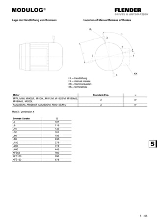


![MODULOG®
5 - 68
Fremdbelüftung External fan unit
Kühlart IC416A (EN 60034-6/IEC 60034-6) Cooling type IC416A (EN 60034-6/IEC 60034-6)
Für Motoren bei denen die Belüftung durch den Eigenlüfter
nicht ausreicht, z.B. bei Schalthäufigkeit, Umrichterbetrieb
etc. oder konstruktiv nicht möglich ist, vgl. dazu "Kombination
von Zusatzausstattungen, Ein- und Anbauten", stehen
Fremdbelüftungseinheiten zur Verfügung.
If ventilation by the motor driven fan is not possible or suf-
ficient, motors can be supplied with forced cooling (e.g. high
number of starts, frequency control or motor designs with ad-
ditional equipment like speed indicators, etc.).
Technische Daten Technical data
In dem Klemmenkasten der Fremdbelüftungseinheit ist
generell ein Kondensator vorhanden.
Dadurch können sie wahlweise an Einphasen-Wechselstrom-
Netzen (U1~) oder an Dreiphasen-Wechselstrom-Netzen
(U3~) mit nachstehenden Spannungen betrieben werden.
Within the terminal boxe of the external fan unit generally a ca-
pacitor is installed.
Therefore they can be likewise operated on single phase AC-
mains (U1 ~) or three phase AC-mains (U3 ~) at the following
voltages.
U1 ~: Einphasen-Wechselspannung
r (∆) 230 - 277V 50 // 60Hz
r (∆) 100 - 135V 50 // 60Hz
U3 ~: Dreiphasen-Wechselspannung
∆ 220 - 290V // 220 - 332V 50 // 60Hz
Y 380 - 500V // 380 - 575V 50 // 60Hz *)
Andere Spannungen auf Anfrage.
U1 ~: Singlephase AC-voltage
r (∆) 230 - 277V 50 // 60Hz
r (∆) 100 - 135V 50 // 60Hz
U3 ~: 3ph. AC-voltage
∆ 220 - 290V // 220 - 332V 50 // 60Hz
Y 380 - 500V // 380 - 575V 50 // 60Hz *)
Other voltages on request.
*) = Auslieferungszustand
Die Schaltungen ∆ oder r (∆) können bei der Installation ent-
sprechend den Schaltbildern in den Klemmenkästen bzw.
nachstehend unter „Elektrischer Anschluss“, vorgenommern
werden.
*) = Delivery Condition
The connections ∆ or r (∆) can be effected during installation
according to the connection diagrams within the terminal bo-
xes, or to following under „Electrical connection“ respectively.
Motor U1 ~ r (∆) 230 - 277V 50//60Hz U1 ~ r (∆) 100 - 135V 50//60Hz
P I C P I C
[W] [A] [µF] [W] [A] [µF]
MI71 50Hz 28 0,10
1,5
44 0,30 2,0
60Hz 41 0,12 47 0,24 2,0
MI80 50Hz 29 0,11
1,5
44 0,30 3,0
60Hz 44 0,13 57 0,27 3,0
MI90S/L 50Hz 71
0,25 1,5
78 0,57 6,0
60Hz 88 102 0,46 6,0
MI100L 50Hz 72 0,25
2,0
78 0,54 6,0
60Hz 88 0,28 105 0,53 6,0
MI112M 50Hz 73 0,26
3,0
80 0,55 6,0
60Hz 107 0,31 115 0,60 6,0
MI132S/M 50Hz 115 0,40
5,0 - - -
60Hz 185 0,59
MI160M/L 50Hz 225 0,93 10
- - -
60Hz - - -
MI180M/L 50Hz 225 0,93 10
- - -
60Hz - - -
MI200L 50Hz 225 0,93 10
- - -
60Hz - - -
P = maximale Leistungsaufnahme
I = maximale zulässige Stromaufnahme
C = Kondensator
P = max. Input power
I = max. admissible current consumption
C = Capacitor](https://image.slidesharecdn.com/flendercavex-170315053907/85/CAVEX-Flender-Siemens-273-320.jpg)
![MODULOG®
5 - 69
Motor U3 ~ ∆ /Y 220 - 290 / 380-500 //
220 - 332 / 380 - 575V 50//60Hz
P I
[W] [A]
MI71 50Hz 30 0,10 / 0,05
60Hz 33 0,10 / 0,06
MI80 50Hz 31 0,10 / 0,05
60Hz 34 0,10 / 0,06
MI90S/L 50Hz 85 0,28 / 0,16
60Hz 90 0,26 / 0,15
MI100L 50Hz 86
0,28 / 0,16
60Hz 93
MI112M 50Hz 85 0,27 / 0,15
60Hz 94 0,28 / 0,16
MI132S/M 50Hz 138 0,45 / 0,24
60Hz 148 0,24 / 0,16
MI160M/L 50Hz 220 0,71 / 0,40
60Hz 280 0,85 / 0,51
MI180M/L 50Hz 220 0,71 / 0,40
60Hz 280 0,85 / 0,51
MI200L 50Hz 220 0,85 / 0,51
60Hz 280 0,71 / 0,40
P = maximale Leistungsaufnahme
I = maximale zulässige Stromaufnahme
C = Kondensator
P = max. Input power
I = max. admissible current consumption
C = Capacitor](https://image.slidesharecdn.com/flendercavex-170315053907/85/CAVEX-Flender-Siemens-274-320.jpg)

![MODULOG®
5 - 71
Rücklaufsperren Backstop equipment
Soll ein Rücklauf des abgeschalteten Antriebs verhindert wer-
den, ist es möglich, Motoren mit mechanischer Rücklaufsper-
re zu verwenden.
Die Rücklaufsperren sind wartungsfrei und haben einzeln an-
gefederte Klemmkörper.
Die Sperren werden mit Dauerschmierung geliefert. Die
Klemmkörper haben abhebende Tendenz; d.h. sie heben
nach dem Anfahren auf Grund der Zentrifugalkraft selbsttätig
ab. Verschleiß tritt deshalb bei Nenndrehzahl des Motors
nicht auf.
Where reverse running of the switched-off drive must be avo-
ided, the use of motors equipped with a mechanical backstop
is possible.
The Backstops are maintenance-free and have separatey,
spring loaded clamping pieces.
The backstops are delivered with a long-term lubrication. The
clamping pieces have a tendency to lift automatically after
starting due to the centrifugal force. Thus at the rated speed
of motor there is no wear.
Die Rücklaufsperre darf nicht als Sicherung gegen fal-
sche Drehrichtung infolge Schaltung gegen die Sperre
eingesetzt werden!
Bei Motorbetriebsdrehzahlen < nabh, z.B. 8- oder 12-poli-
ge Motoren oder Umrichterbetrieb, ist Rücksprache erfor-
derlich!
Under no circumstances should the backstop be used as
a protection against wrong direction of rotation due to fal-
se connetion of motor!
At motor operating speeds <nabh, e.g. 8- or 12-pole mo-
tors or frequency innverter operation, please contact our
agency!
Für die Motor-Leistung gelten die Auswahltabellen dieser Li-
ste. Die Zuordung der Rücklaufsperren zu den Baugrößen
kann untenstehender Tabelle entnommen werden.
The electric data sheets in this catalogue are valid for the mo-
tor nominal power. See the table below for the backstops to be
used for different frame sizes.
Längenmaße Length dimensions
Bei Motoren MI71 bis AM200L gelten bei angebauter Rück-
laufsperre die Maße „KB“.
With motors MI71 through AM200L dimensions „KB“ can be
used.
Motor TAmax
[Nm]
TSP
[Nm]
nabh
[min-1
]
MI71 5,6
100 890
17,9
MI80 11,5 8,7
MI90S/L 23
150 860
6,5
MI100L 46 3,3
MI112M 64 2,3
MI132S/M 140 420 750 3,0
MI160M/L 225 580 730 2,6
MI180M/L 487
1050 670
2,2
MI200L 450 2,3
AMI225S
720
1350 630
1,9
AMI225M
AMI250M 639
2,1AMI280S
1278
2700 400AMI280M
AMI315S 1633
1,7AMI315M
3842 6500 320
AMI315L
TAmax = Größtes Anzugsdrehmoment innerhalb einer Baugrö-
ße. Genaue Werte siehe Leistungstabellen
TAmax = Highest starting torque within a frame size. For details
see motor data sheets
TSP = Nennmoment der Rücklaufsperre TSP = Rated torque of the backstop
nabh = Abhebedrehlzahl der Rücklaufsperre nabh = Lift-off speed of the backstop
Smin = Mindestsicherheitsfaktor innerhalb einer Baugröße Smin = Minimum safety factor within a frame size
Smin
Tsp
TAmax
-------------------=](https://image.slidesharecdn.com/flendercavex-170315053907/85/CAVEX-Flender-Siemens-276-320.jpg)


Das Dokument ist der Katalog für die Cavex® Schneckengetriebe der Flender Tübingen GmbH und enthält technische Informationen, allgemeine Hinweise sowie Bestellangaben zu den Produkten. Es werden spezifische Anforderungen und Bedingungen für den Betrieb, die Installation und die Auswahl der Getriebegrößen behandelt. Darüber hinaus finden sich Informationen zu Sicherheitsbestimmungen, Betriebsfaktoren und den Vorteilen der verwendeten verzahnungsprinzipien.


![Catalogo de rolamentos_fag_(br)[1]](https://cdn.slidesharecdn.com/ss_thumbnails/catalogoderolamentosfagbr1-140806135814-phpapp01-thumbnail.jpg?width=640&height=640&fit=bounds)


