Downloaden Sie, um offline zu lesen


![BESAPLAST®
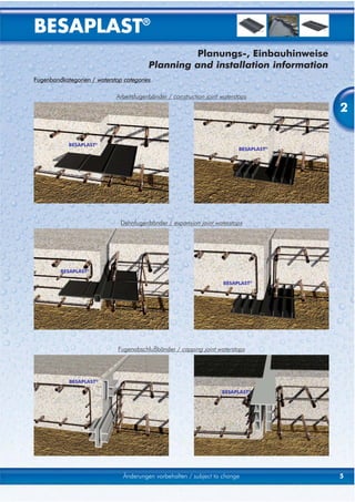
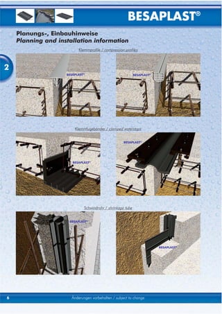
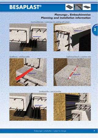
Planungs-, Einbauhinweise
Planning and installation information
Allgemeine Hinweise / general instructions
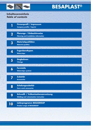
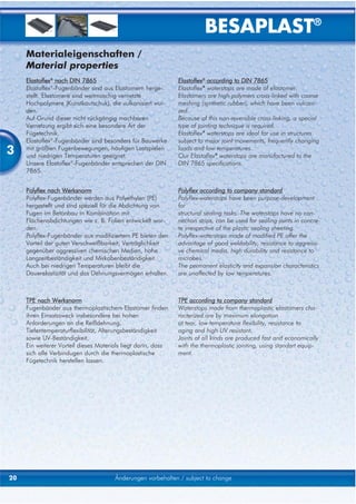
Funktionsweise des Fugenbandes/
2 Funktionality of waterstops
A = Dehnteil / elongation part
B = Dichtteil / sealing part
Abdichtungssystem / Sealing system
Bei der Planung ist darauf zu achten, daß die
Abdichtung ein in sich geschlossenes System ergibt.
Nach Möglichkeit beachten:
• gerade Fugenverläufe,
• Wechsel von außen- u. innenliegenden
Fugenbändern vermeiden.
While planning, please ensure that the proofing is a
closed system.
Whenever possible, please consider the following:
• straight of joints,
• no alternation between internal and external
waterstops.
Betondeckung / Concrete cover
Zwischen dem Fugenband und der Stahlarmierung ist
ein lichter Abstand von ≥ 20 mm einzuhalten.
Keep a distance of ≥ 20 mm between waterstop and
reinforcement.
Biegeradius / Bending radius
Folgende Biegeradien (um die x-Achse; siehe
Abbildung rechts) sind einzuhalten:
• innenliegende Arbeitsfugenbänder: r ≥ 150 mm
• innenliegende Dehnfugenbänder: r ≥ 250 mm
• außenliegende Fugenbänder: r ≥ 50 x f mm
• Fugenabschlußbänder: r ≥ 30 x a mm
r
The following bendingradii (around the x-axis) are to
be keeped at waterstops: r
• internal construction joint waterstops: r ≥ 150 mm
• internal expansion joint waterstops: r ≥ 250 mm
• external waterstops: r ≥ 50 x f mm
• capping joint waterstopsr ≥ 30 x a mm
8 Änderungen vorbehalten, Einheit [mm] / subject to change, unit [mm]](https://image.slidesharecdn.com/besaplastengdeversion-130115080456-phpapp01/85/Profile-hidroizolante-tip-Besaplast-10-320.jpg)
![BESAPLAST®
Planungs-, Einbauhinweise
Planning and installation information
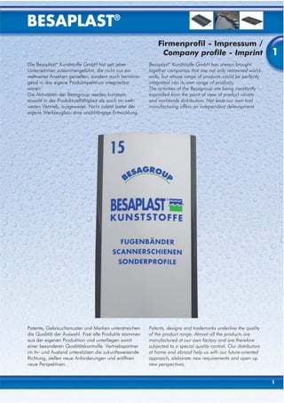
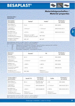
Bemessung / dimensioning
DIE FOLGENDEN ANGABEN BEZIEHEN SICH THE FOLLOWING INFORMATION ARE ONLY VALID
LEDIGLICH AUF STANDARTSITUATIONEN! FOR STANDARDSITUATIONS
2
Hinweise Explanation
• Für Arbeitsfugen gelten die gleichen • These diagrams are valid for construction
Bedingungen wie für Dehnfugenbänder. joints as well as for expansion joints.
• Die Breite von innenliegenden Fugenbändern • The width of internal waterstop must not be
darf die Bauteilstärke nicht überschreiten more than thickness of structural elements.
• Gültig für Ausgangsfugenweiten wnom: • Designed joint width wnom:
- außenliegende Fugenbänder: 20 mm - external waterstops: 20 mm
- innenliengende Fugenbänder: 20 - 30 mm - internal waterstops: 20 - 30 mm
- Fugenabschlußbänder: 20 - 30 mm - capping joint waterstops: 20 - 30 mm
Bemessung Dimensioning
Berechnung der vorhandenen resultierenden Calculating of existing result of movement:
Verformung:
vR = v(vx2 + vy2 + vz2) vR = v(vx2 + vy2 + vz2)
Zulässige Verformung: Permissible total deformation:
• Siehe Bemessungediagramme, • see diagrams for dimensioning,
(abhängig vom Wasserdruck) (depe on water pressure)
• Randbedingungen: • limiting conditions:
vx: bei wnom = 20mm: wmin ≥ 15mm vx: at wnom = 20 mm: wmin ≥ 15 mm
bei wnom = 30mm: wmin ≥ 20mm at wnom = 30 mm: wmin ≥ 20 mm
vy: ≤ wnom vy: ≤ wnom
vz: ≤ wnom vz: ≤ wnom
v = Verformung v = deformation
w = Fugenbreite w = joint width
BESAPLAST® BESAPLAST®
Vx Vx
Vy Vy
Vz Vz
Änderungen vorbehalten, Einheit [mm] / subject to change, unit [mm] 9](https://image.slidesharecdn.com/besaplastengdeversion-130115080456-phpapp01/85/Profile-hidroizolante-tip-Besaplast-11-320.jpg)
![BESAPLAST®
Planungs-, Einbauhinweise
Planning and installation information
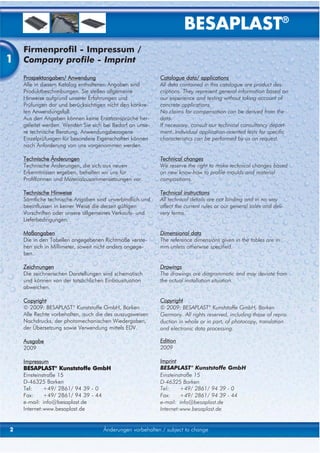
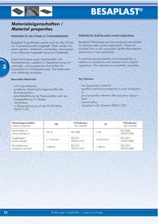
Besaflex® Serie D, Werksnorm / company standard Nitriflex® Serie D, DIN 18541
2
Elastoflex® Serie FM, DIN 7865 Elastoflex® Serie FMS, DIN 7865
10 Änderungen vorbehalten, Einheit [mm] / subject to change, unit [mm]](https://image.slidesharecdn.com/besaplastengdeversion-130115080456-phpapp01/85/Profile-hidroizolante-tip-Besaplast-12-320.jpg)
![BESAPLAST®
Planungs-, Einbauhinweise
Planning and installation information
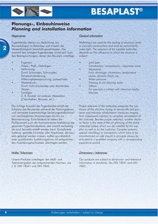
Besaflex® Serie AD, Werksnorm / company standard Besaflex® Serie FV, Werksnorm / company standard
2
Nitriflex® Serie DA, DIN 18541 Nitriflex® Serie FA, DIN 18541
Elastoflex® Serie AM, DIN 7865 Elastoflex® Serie FAE, DIN 7865
Änderungen vorbehalten, Einheit [mm] / subject to change, unit [mm] 11](https://image.slidesharecdn.com/besaplastengdeversion-130115080456-phpapp01/85/Profile-hidroizolante-tip-Besaplast-13-320.jpg)
![BESAPLAST®
Planungs-, Einbauhinweise
Planning and installation information
Ausschreibungstext / tender specification
Pos. ___________ Innen(außen)liegendes Arbeits(Dehn)fugenband
2 BESAPLAST®-Fugenband aus:
Besaflex® (Nitriflex®/ Elastoflex®/ Polyflex / TPE / Besaflex® nach BS)
Typ: ___________________ o. vergleichbar.
Inlusive aller Formstücke und Systeme, sach- und fachgerecht
gem. den Herstellervorschriften liefern und einbauen.
Hersteller: BESAPLAST® Kunststoffe GmbH
Einsteinstraße 15
D-46325 Borken
Tel.: +49/ 2861/ 94 39 - 0
Fax: +49/ 2861/ 94 39 - 44
e-mail: info@besaplast.de ___________ m
Item ___________ Internal(external) construction(expansion)joint waterstop
BESAPLAST®-waterstop made of:
Besaflex® (Nitriflex®/ Elastoflex®/ Polyflex / TPE / Besaflex® to BS)
Type: ___________________ or comparable.
Inclusive all special fittings, proper and professional installation
in accordance with the manufacturer's instructions.
Manufacturer: BESAPLAST® Kunststoffe GmbH
Einsteinstraße 15
D-46325 Borken
Tel.: +49/ 2861/ 94 39 - 0
Fax: +49/ 2861/ 94 39 - 44
e-mail: info@besaplast.de ___________ m
12 Änderungen vorbehalten, Einheit [mm] / subject to change, unit [mm]](https://image.slidesharecdn.com/besaplastengdeversion-130115080456-phpapp01/85/Profile-hidroizolante-tip-Besaplast-14-320.jpg)
![BESAPLAST®
Planungs-, Einbauhinweise
Planning and installation information
Transport und Lagerung / transportation and storaging
Anlieferung / delivery
Die Anlieferung erfolgt grundsätzlich auf Paletten. 2
In general the delivery is carried out on pallets.
Prüfung / checking
Nach Anlieferung ist die Ware auf Vollständigkeit und
Unversehrtheit zu prüfen.
After delivery the goods have to be inspected for com-
pleteness and faultless appearance.
Lagerung / storaging
Bei Lagerung ist auf einen stabilen Untergrund zu
achten. Thermoplastische Fugenbänder sind nach
Möglichkeit im Magazin zu lagern.
The goods have to be stored on solid ground.
Thermoplastic waterstops should be stored in a depot
to avoid deformations.
Fugenbandsysteme / waterstop-systems
Fugenbansysteme nicht über mehrere Monate lagern.
Insbesondere thermoplastische Fugenbänder können
unter natürlichen Bedingungen ihre Längen ändern.
Storaging of waterstop-systems (particularly thermo-
plastic waterstops) should not be for an extended
period of time. Changes of length can be the effect of
natural thermal conditions.
Änderungen vorbehalten, Einheit [mm] / subject to change, unit [mm] 13](https://image.slidesharecdn.com/besaplastengdeversion-130115080456-phpapp01/85/Profile-hidroizolante-tip-Besaplast-15-320.jpg)
![BESAPLAST®
Planungs-, Einbauhinweise
Planning and installation information
Einbau / Installation
Verformungen / deformations
2 Leichte Verformungen (lagerungs- oder transportbe-
dingt) können durch Wärmebehandlung beseitigt wer-
den.
Thermoplastische Fugenbänder schmelzen ab
ca. 140 °C!
Facile deformations (caused by storage or transport
conditions) can be corrected by heat treatments.
Thermoplastic waterstops are fusible at
approx. 140 °C!
Verlegung / laying
Die Verlegung muß falten- und verwerfungsfrei erfol-
gen.
The laying must be free of crinkles and distortion.
Lage / position
Der Einbau von außenliegenden Fugenbändern darf
niemals mit den Sperrankern nach unten erfolgen!
Es besteht die Gefahr von Lufteinschlüssen.
The installation of external waterstops should never be
done by putting the achor ribs downside! This could
cause blowholes and potential leakage.
Enflüftung / venting
Horizontale innenliegende Fugenbänder müssen V-för-
ming (~15°)ingebaut werden, um eine optimale
Entlüfung zu gewährleisten.
For the best venting, the installation of horizontal inter-
nal waterstops should be done in V-form (~15°).
14 Änderungen vorbehalten, Einheit [mm] / subject to change, unit [mm]](https://image.slidesharecdn.com/besaplastengdeversion-130115080456-phpapp01/85/Profile-hidroizolante-tip-Besaplast-16-320.jpg)
![BESAPLAST®
Planungs-, Einbauhinweise
Planning and installation information
Befestigung / fixing
Die Befestigung erfolgt je nach Fugenbandtyp: 2
• Innenliegende Fugenbänder mit
Fugenbandklammern,
Stahlstabilisierung oder
Typ 1 Typ 2 Typ 3
Ösen.
• Außenliegende Fugenbänder und Fugenabschluß-
bänder mit
Fugenbandklammern und/ oder
Doppelkopfnägeln.
Abstand der Befestigung: ≤ 25 cm
Für den Einbau gilt:
• lagesicher,
• symmetrisch zur Fugenachse.
Fixing depends on the type of waterstop:
• internal waterstops with
clips,
steel bar reinforcement
eyelets.
• external waterstops and capping joint waterstops
with
clips and/ or
two-head-nails.
Distance between fixing: ≤ 25 cm
The following is important for installing:
• secure bedding to avoid slippings,
• symmetric to the joint axis.
Verwahrung / storage
Bei der Verwahrung sind freie Fugenbandenden
gegen Beschädigungen zu schützen.
The open ends of waterstops have to be protected
from damages during storage.
Änderungen vorbehalten, Einheit [mm] / subject to change, unit [mm] 15](https://image.slidesharecdn.com/besaplastengdeversion-130115080456-phpapp01/85/Profile-hidroizolante-tip-Besaplast-17-320.jpg)
![BESAPLAST®
Planungs-, Einbauhinweise
Planning and installation information
Ausschalen / stripping
2 Beim Ausschalen sind insbesondere außenliegende
Fugenbänder gegen Beschädigungen zu schützen.
Particularly external waterstops have to be protected
from damages while stripping the forms.
Kontrolle / checking
Sofern möglich, sind die Fugenbänder nach dem
Ausschalen auf Unversehrtheit zu prüfen.
Check the waterstops for damages after stripping the
forms whenever possible.
16 Änderungen vorbehalten, Einheit [mm] / subject to change, unit [mm]](https://image.slidesharecdn.com/besaplastengdeversion-130115080456-phpapp01/85/Profile-hidroizolante-tip-Besaplast-18-320.jpg)
![BESAPLAST®
Planungs-, Einbauhinweise
Planning and installation information
Maßtoleranzen / general tolerances
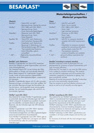
Fugenbänder bestehen aus einem hoch elastischem Waterstops consist of a highly elastic material. When
Material. Bei Temperatureinwirkung und/ oder
Zwängungen (z. B. Stauchen, Strecken, ...) verändern
temperatures changes and/ or waterstops are upseted
or stretched the length can change. Also tolerances of 2
sich Längenmaße. Darüber hinaus können Toleranzen manufacturing and not professional installing can
und "wellige oder überspannte Verlegung" zu cause differences of length.
Längendifferenzen führen.
Daher gilt für jedes Fugenbandsystem, welches The following information are valid for all waterstop-
"gefangene Maße" enthält: systems with defined dimensions:
1.) Prüfung 1.) Checking
Das Fugenbandsystem ist nach Erhalt auf Maß- The waterstop systems have to be checked
genauigkeit zu überprüfen, geschützt und zwangfrei zu immediately after receipt. Apparent defects in
lagern. Bei nicht akzeptierten Maßabweichungen sind measurement or size have to be reported to us without
diese unverzüglich zu melden. delay. The delivered goods have to be kept safe and
loosely stored.
2.) Einbau
Das Fugenbandsystem muss vor der Betonage zur 2.) Installing
Gänze in die vorgesehene Lage eingebaut werden At first the whole waterstopsystem has to be installed
und ist danach zu befestigen. Dadurch soll erreicht and after this it has to be fixed. The result is:
werden, daß:
• Maßdifferenzen rechtzeitig erkannt werden, • recocnizability of measure differences before
bevor das Fugenbandsystem teilweise (halbseitig) concrete is encased.
einbetoniert wurde. Maßkorrekturen im Corrections of encased waterstops are difficult
eingebauten Zustand sind schwierig und and costly.
kostenintensiv. • that not fixed waterstopends can not shift.
• unbefestigte Fugenbandenden nicht wandern. • small deviation can be balanced.
(durch "welligen" Einbau zu kurz, oder durch
"überstreckten" Einbau zu lang werden)
• geringe Maßabweichungen beim Verlegen
ausgeglichen werden können.
3.) Maßabweichungen
Maßabweichungen bis 3% können im Werkstoff und/ 3.) Tolerances
oder im unsachgemäßen Umgang mit den Fugen- Lenght differences to 3 % are possible due to the
bandsystemen begründet sein. Maßabweichungen, properties of the material and can also be caused by
die korrekten bzw. sicheren Einbau nicht mehr zulas- improper installation of the waterstop systems.
sen, können von uns behoben werden.
Measurement differences that allow no correct and
4.) Korrektur safe installation can be remedied by us.
Für Maßkorrekturen zu unseren Lasten müssen die
Punkte 1 bis 3 erfüllt sein. Ansonsten werden alle uns
entstehenden Kosten in Rechnung gestellt. 4.) Correction of defects
If the correction is necessary because of wrong
delivery from us and the customer has fulfilled his
duties mentioned in item 1 and 2, than the correction
will be done at our expense. Otherwise we will charge
our work according to our price list.
Änderungen vorbehalten, Einheit [mm] / subject to change, unit [mm] 17](https://image.slidesharecdn.com/besaplastengdeversion-130115080456-phpapp01/85/Profile-hidroizolante-tip-Besaplast-19-320.jpg)
![BESAPLAST®
Planungs-, Einbauhinweise
Planning and installation information
Fügungen / connections
Allgemeines General information
2 • Vor Ort sind nur stumpfe Verbindungen zuge-
lasen
• On site it is only allowed ot make buttom
connections.
• Ecken, T-Stücke, Kreuzungen sowie Übergän- • Corners, T-pieces, cross section and connecti
ge unterschiedlicher Fugenbänder sind werks- ons between different waterstop-types have to
seitig herzustellen. be done in our factory.
• Die Durchführung von Fügungen vor Ort sind • Connections on site have to be made by
ausschließlich durch ausgebildetes Fachpersonal qualified persons.
zulässig. • Air temperature should be not less than 0 °C.
• Die Umgebungstemperatur sollte 0 °C nicht If neccessary a tent has to be pitched.
unterschreiten. Ggf. ist der Aufbau eines
Zeltes o. ä. erforderlich.
Fügemethoden / methods for connecting
Methode / methode Schweißen / welding Vulkanisieren / vulcanizing
• Besaflex
Betrifft folgende Materialien / • Nitriflex
• Elastoflex
valid for following materials: • Polyflex
• TPE
Materialeigenschaft / schmelzbar / nicht schmelzbar /
material properties: fusible not fusible
• Schweißgerät,
• Schweißbeil,
• Schweißschwert /
• Heißluftfön • Vulkanisationsgerät /
Fügung ist ausführbar mit /
connection can be done by:
• welding machine • vulcanizing machine
• axe-shape-welding tool /
• electric heater blade
• hot air blower
Mindestabstände / minimum distance
Folgende Mindestabstände von Fugenbandstößen The following minimum distances are to keep:
sind einzuhalten:
• Distance among each other:
• Abstand untereinander: ≥ 50 cm
≥ 50 cm • Distance from factory fabricated connections:
• Abstand zu Werksverbindungen: ≥ 50 cm
≥ 50 cm • Distance of ending waterstops:
• Abstand bei auslaufenden Fugenbandenden: (In case of multiple concrete sections)
(Dies betrifft mehrere Betonierabschnitte) ≥ 100 cm
≥ 100 cm
18 Änderungen vorbehalten, Einheit [mm] / subject to change, unit [mm]](https://image.slidesharecdn.com/besaplastengdeversion-130115080456-phpapp01/85/Profile-hidroizolante-tip-Besaplast-20-320.jpg)
![BESAPLAST®
Übersicht
Digest
- Innenliegende Arbeitsfugenbänder - Internal construction joint waterstops
- Innenliegende Dehnfugenbänder - Internal expansion joint waterstops
- Außenliegende Arbeitsfugenbänder - External construction joint waterstops
- Außenliegende Dehnfugenbänder - External expansion joint waterstops
- Fugenabschlußbänder - Capping joint waterstops
- Klemmprofile - Compression profiles
- Klemmfugenbänder - Clamped waterstops
- Schwindrohr - Shrinkage tube
- Anschweißfugenbänder - Waterstopf for welding with sheets
4
- Quellband - Swelling rubber
- Injektionsschlauch - Injection tube
- Sonderprofile - Special profiles
Änderungen vorbehalten, Einheit: [mm] / subject to change, unit: [mm] 23](https://image.slidesharecdn.com/besaplastengdeversion-130115080456-phpapp01/85/Profile-hidroizolante-tip-Besaplast-25-320.jpg)
![BESAPLAST®
Innenliegende Arbeitsfugenbänder
Internal construction joint waterstops
Besaflex® nach Werksnorm
Besaflex® to company standard
Typ / type a b c f
A 100 100 40 3,0 10
A 120 120 45 3,0 10
A 150 150 45 3,0 10
A 200 200 70 3,0 15
A 240 240 80 3,5 15
A 320 320 110 4,5 15
A 500 500 150 6,0 20
Nitriflex® nach DIN 18541
Nitriflex® to DIN 18541
4 Typ / type
A 190 1)
a
190
b
70
c
3,5
f
15
A 240 240 80 4,0 15
A 320 320 110 5,0 15
A 500 500 120 6,5 20
1)
nach/ to DIN 18541 Teil/ part 2
Elastoflex® nach DIN 7865
Elastoflex® to DIN 7865
Typ / type a b c f
F 200 100 75 7,0 32
F 250 120 80 8,0 32
F 300 150 100 8,0 32
DIN 7865 Teil/ part 2
F 250-2 250 80 6,0 32
F 300-2 300 100 6,0 32
F 350-2 350 120 6,0 32
Polyflex nach Werksnorm
Polyflex to company standard
Typ / type a b c f
AP 200 200 80 3,0 15
AP 240 240 90 3,5 15
AP 320 320 110 4,5 15
AP 500 500 120 6,0 20
Besaflex® nach British standard (BS)
Besaflex® to British standard (BS)
Typ / type a b c f
CC 150 150 116 5,0 20
CC 200 200 87 5,0 20
CC 250 250 116 6,0 24
CC 300 300 166 7,0 24
24 Änderungen vorbehalten, Einheit: [mm] / subject to change, unit: [mm]](https://image.slidesharecdn.com/besaplastengdeversion-130115080456-phpapp01/85/Profile-hidroizolante-tip-Besaplast-26-320.jpg)
![BESAPLAST®
Innenliegende Arbeitsfugenbänder
Internal construction joint waterstops
Besaflex® nach Werksnorm
Besaflex® to company standard Mit innenliegender Armierung /
with internal steel bar reinforcement
Typ / type a b c f
ASI 200 200 70 3,5 15
ASI 240 240 80 3,5 15
ASI 320 320 100 4,0 15
Nitriflex® nach DIN 18541
Nitriflex® to DIN 18541 Mit innenliegender Armierung /
with internal steel bar reinforcement
Typ / type a b c f
ASI 200 D 1)
200 70 3,5 15
ASI 240 D 240 80 4,0 15
ASI 320 D 320 100 5,0 15
1)
nach/ to DIN 18541 Teil/ part 2
4
Besaflex® nach Werksnorm
Besaflex® to company standard Mit aussenliegender Armierung /
with external steel bar reinforcement
Typ / type a b c f
AS 100 100 50 3,0 10
AS 120 120 60 3,0 10
AS 150 150 60 3,0 10
AS 200 200 70 3,5 15
AS 240 240 80 3,5 15
AS 320 320 100 4,5 15
Mit aussenliegender Armierung /
Nitriflex® nach DIN 18541
with external steel bar reinforcement
Nitriflex® to DIN 18541
Typ / type a b c f
AS 200 D 1)
200 70 3,5 15
AS 240 D 240 80 4,0 15
AS 320 D 320 100 5,0 15
1)
nach/ to DIN 18541 Teil/ part 2
Extra stark dimensioniert /
extra thick profile
Nitriflex® nach DIN 18541
Nitriflex® to DIN 18541
Typ / type a b c f
A 260 DBS 260 120 9,0 26
A 320 DBS 320 165 10,0 26
A 400 DBS 400 190 11,0 30
Mit seitlichen Stahllaschen /
with steel plates
Elastoflex® nach DIN 7865
Elastoflex® to DIN 7865
Typ / type a b c f
FS 310 310 80 10 22
Änderungen vorbehalten, Einheit: [mm] / subject to change, unit: [mm] 25](https://image.slidesharecdn.com/besaplastengdeversion-130115080456-phpapp01/85/Profile-hidroizolante-tip-Besaplast-27-320.jpg)
![BESAPLAST®
Innenliegende Dehnfugenbänder
Internal expansion joint waterstops
Besaflex® nach Werksnorm
Besaflex® to company standard
Typ / type a b c f k
D 120 120 70 3,0 10 10
D 150 150 70 3,0 10 10
D 200 200 90 3,5 15 10
D 240 240 90 4,0 15 20
D 320 320 110 5,0 15 20
D 350 350 120 5,0 15 20
D 500 500 150 6,0 20 20
Nitriflex® nach DIN 18541
Nitriflex® to DIN 18541
4 Typ / type
D 190 1)
a
190
b
75
c
4,0
f
15
k
10
D 240 240 95 4,5 15 20
D 240/6 240 95 6,0 25 20
D 240/9 240 95 9,0 25 20
D 320 320 110 5,5 15 20
D 320/6 320 110 6,0 25 20
D 320/9 320 110 9,0 25 20
D 350 350 120 6,0 15 20
D 500 500 155 6,5 20 20
1)
nach/ to DIN 18541 Teil/ part 2
Elastoflex® nach DIN 7865
Elastoflex® to DIN 7865
Typ / type a b c f k
FM 200 200 110 7,0 32 20
FM 250 250 125 8,0 32 20
FM 300 300 175 8,0 32 20
FM 350 350 180 12,0 38 20
FM 400 400 210 12,0 38 20
FM 500 500 300 13,0 38 20
DIN 7865 Teil/ part 2
FM 250-2 250 125 6,0 26 20
FM 300-2 300 175 6,0 28 20
FM 350-2 350 180 6,0 30 20
Polyflex nach Werksnorm
Polyflex to company standard
Typ / type a b c f k
DP 200 200 80 3,5 15 10
DP 240 240 90 4,0 15 20
DP 320 320 110 5,0 15 20
DP 500 500 150 6,0 20 20
26 Änderungen vorbehalten, Einheit: [mm] / subject to change, unit: [mm]](https://image.slidesharecdn.com/besaplastengdeversion-130115080456-phpapp01/85/Profile-hidroizolante-tip-Besaplast-28-320.jpg)
![BESAPLAST®
Innenliegende Dehnfugenbänder
Internal expansion joint waterstops
Besaflex® nach British standard (BS)
Besaflex® to British standard (BS)
Typ / type a b c f k
CE 150 150 116 5,0 20 20
CE 200 200 87 5,0 20 20
CE 250 250 116 6,0 24 20
CE 300 300 166 7,0 24 20
Extra stark dimensioniert /
Nitriflex® nach DIN 18541
extra thick profile
Nitriflex® to DIN 18541
Typ / type a b c f k
D 260 DBS
D 350 DBS
260
350
120
170
9,0
11,0
28
30
20
20
4
D 400 DBS 400 190 11,0 32 20
Mit seitlichen Stahllaschen /
Elastoflex® nach DIN 7865
with steel plates
Elastoflex® to DIN 7865
Typ / type a b c f k
FMS 350 350 120 10,0 32 20
FMS 400 400 170 11,0 32 20
FMS 500 500 230 13,0 32 20
Mit Stahllaschen u. Mittelschlauchummantelung /
Elastoflex® nach DIN 7865
with steel plates and tube sheathing
Elastoflex® to DIN 7865
Typ / type a b c f k
FMS 400 DS 400 170 11,0 35 20
FMS 500 DS 500 230 13,0 35 20
Mit Mittelschlauchummantelung /
Elastoflex® nach DIN 7865
with tube sheathing
Elastoflex® to DIN 7865
Typ / type a b c f k
FM 350 DS 500 230 13,0 35 20
Änderungen vorbehalten, Einheit: [mm] / subject to change, unit: [mm] 27](https://image.slidesharecdn.com/besaplastengdeversion-130115080456-phpapp01/85/Profile-hidroizolante-tip-Besaplast-29-320.jpg)
![BESAPLAST®
Außenliegende Arbeitsfugenbänder
External construction joint waterstops
Besaflex® nach Werksnorm
Besaflex® to company standard
Anker/
Typ / type a b c f
anchor
AA 200 200 80 3,5 20 4
AA 250 240 90 4,0 25 4
AA 250/35 240 90 4,5 35 4
AA 250/45 240 90 4,5 45 4
AA 320 320 110 4,0 25 6
AA 320/35 320 110 4,5 35 6
AA 320/45 320 110 4,5 45 6
AA 500 500 120 4,0 25 8
AA 500/35 500 120 4,5 35 8
4 AA 625/35
AA 800
625
800
300
300
5,5
5,5
35
25
10
12
Nitriflex® nach DIN 18541
Nitriflex® to DIN 18541
Anker/
Typ / type a b c f
anchor
AA 240/25 240 90 4,5 25 4
AA 240/35 240 90 5,0 35 4
AA 240/45 240 90 5,0 45 4
AA 320/25 320 110 4,5 25 6
AA 320/35 320 110 5,0 35 6
AA 320/45 320 110 5,0 45 6
AA 500/25 500 120 4,5 25 8
AA 500/35 500 120 5,0 35 8
Elastoflex® nach DIN 7865
Elastoflex® to DIN 7865
Anker/
Typ / type a b c f
anchor
A 250 250 100 6,0 31 4
A 350 350 100 6,0 31 6
A 500 500 150 6,0 31 8
DIN 7865 Teil/ part 2
A 250-2 250 100 5,5 30 4
Polyflex nach Werksnorm
Polyflex to company standard
Anker/
Typ / type a b c f
anchor
AAP 240 240 90 4,0 25 4
AAP 320 320 110 4,0 25 6
28 Änderungen vorbehalten, Einheit: [mm] / subject to change, unit: [mm]](https://image.slidesharecdn.com/besaplastengdeversion-130115080456-phpapp01/85/Profile-hidroizolante-tip-Besaplast-30-320.jpg)
![BESAPLAST®
Außenliegende Arbeitsfugenbänder
External construction joint waterstops
Besaflex® nach British standard (BS)
Besaflex® to British standard (BS)
Anker/
Typ / type a b c f
anchor
EC 150 150 110 4,5 24 2
EC 200 200 85 4,5 24 4
EC 250 250 110 4,5 24 4
EC 300 300 140 4,5 24 4
EC 330 330 170 4,5 24 4
Besaflex® nach Werksnorm
Besaflex® to company standard
Anker/
Typ / type a1 a2 b1 b2
AA 240 EA 120 120 45 45
anchor
4
4
AA 240 EW 120 120 45 45 4
AA 320 EA 170 170 55 55 6
AA 320 EW 170 170 55 55 6
AA 320 EI 170 170 100 100 4
AA 500 EA 250 250 85 85 8 Ecke A
AA 500 EW 250 250 85 85 8
AA 500 EI 250 250 85 85 8
Nitriflex® nach DIN 18541, Teil 2
Nitriflex® to DIN 18541, part 2
Ecke W
Anker/
Typ / type a1 a2 b1 b2
anchor
AA 240 EA 120 120 45 45 4
AA 240 EW 120 120 45 45 4
AA 320 EA 170 170 55 55 6
AA 320 EW 170 170 55 55 6
AA 320 EI 170 170 100 100 4
AA 500 EA 250 250 85 85 8
AA 500 EW 250 250 85 85 8
AA 500 EI 250 250 85 85 8
Ecke I
Besaflex® nach British standard (BS)
Besaflex® to British standard (BS)
Anker/
Typ / type a1 a2 b1 b2
anchor
EC 240 EA 120 120 45 45 4
EC 240 EW 120 120 45 45 4
Änderungen vorbehalten, Einheit: [mm] / subject to change, unit: [mm] 29](https://image.slidesharecdn.com/besaplastengdeversion-130115080456-phpapp01/85/Profile-hidroizolante-tip-Besaplast-31-320.jpg)
![BESAPLAST®
Außenliegende Dehnfugenbänder
External expansion joint waterstops
Besaflex® nach Werksnorm
Besaflex® to company standard
Anker/
Typ / type a b c f
anchor
AD 200 200 80 3,5 20 4
AD 250 240 90 4,0 25 4
AD 250/35 240 90 4,5 35 4
AD 250/45 240 90 4,5 45 4
AD 320 320 110 4,0 25 6
AD 320/35 320 110 4,5 35 6
AD 320/45 320 110 4,5 45 6
AD 500 500 120 4,0 25 8
AD 500/35 500 120 4,5 35 8
4 Nitriflex® nach DIN 18541
Nitriflex® to DIN 18541
Anker/
Typ / type a b c f
anchor
DA 240/25 240 90 4,5 25 4
DA 240/35 240 90 5,0 35 4
DA 240/45 240 90 5,0 45 4
DA 320/25 320 110 4,5 25 6
DA 320/35 320 110 5,0 35 6
DA 320/45 320 110 5,0 45 6
DA 500/25 500 120 4,5 25 8
DA 500/35 500 120 5,0 35 8
Elastoflex® nach DIN 7865
Elastoflex® to DIN 7865
Anker/
Typ / type a b c f
anchor
AM 250 250 100 6,0 31 4
AM 350 350 100 6,0 31 6
AM 500 500 150 6,0 31 8
DIN 7865 Teil/ part 2
AM 250-2 250 100 5,5 30 4
Polyflex nach Werksnorm
Polyflex to company standard
Anker/
Typ / type a b c f
anchor
ADP 240 240 90 4,0 25 4
ADP 320 320 110 4,0 25 6
30 Änderungen vorbehalten, Einheit: [mm] / subject to change, unit: [mm]](https://image.slidesharecdn.com/besaplastengdeversion-130115080456-phpapp01/85/Profile-hidroizolante-tip-Besaplast-32-320.jpg)
![BESAPLAST®
Außenliegende Dehnfugenbänder
External expansion joint waterstops
Besaflex® nach British standard (BS)
Besaflex® to British standard (BS)
Anker/
Typ / type a b c f
anchor
EE 150 150 110 4,5 24 2
EE 200 200 85 4,5 24 4
EE 250 250 110 4,5 24 4
EE 300 300 140 4,5 24 4
EE 330 330 170 4,5 24 4
Besaflex® nach Werksnorm
Besaflex® to company standard
Anker/
Typ / type a1 a2 b1 b2
AD 240 EA 120 120 50 50
anchor
4
4
AD 240 EW 120 120 50 50 4
AD 320 EA 170 170 60 60 6
AD 320 EW 170 170 60 60 6
AD 500 EA 250 250 90 90 8
AD 500 EW 250 250 90 90 8
Ecke A
®
Nitriflex nach DIN 18541, Teil 2
Nitriflex® to DIN 18541, part 2
Anker/
Typ / type a1 a2 b1 b2
anchor
DA 240 EA 120 120 50 50 4
DA 240 EW 120 120 50 50 4
DA 320 EA 170 170 60 60 6
DA 320 EW 170 170 60 60 6 Ecke W
DA 500 EA 250 250 90 90 8
DA 500 EW 250 250 90 90 8
Besaflex® nach British standard (BS)
Besaflex® to British standard (BS)
Anker/
Typ / type a1 a2 b1 b2
anchor
EE 240 EA 120 120 50 50 4
EE 240 EW 120 120 50 50 4
Änderungen vorbehalten, Einheit: [mm] / subject to change, unit: [mm] 31](https://image.slidesharecdn.com/besaplastengdeversion-130115080456-phpapp01/85/Profile-hidroizolante-tip-Besaplast-33-320.jpg)
![BESAPLAST®
Fugenabschlußbänder
Capping joint waterstops
Besaflex® nach Werksnorm
Besaflex® to company standard
Fugenabschlußband mit 2 Sperranker / Anker/
Capping joint waterstop with 2 anchors Typ / type a b k d f
anchor
FV 20/20 50 20 10 5,0 25 2
FV 20/20/70 70 20 10 5,0 25 2
FV 20/30 50 20 10 5,0 35 2
FV 20/40 70 20 10 5,0 45 2
FV 30/20 50 30 20 5,0 25 2
FV 30/30 50 30 20 5,0 35 2
FV 30/40 70 30 20 5,0 45 2
FV 40/40 70 40 30 5,0 45 2
FV 50/40 70 50 40 5,0 45 2
FV 30/20/2 95 30 20 5,0 25 4
4 Fugenabschlußband mit 4 Sperranker /
FV
FV
30/30/2
40/30/2
95
95
30
40
20
30
5,0
5,0
35
35
4
4
Capping joint waterstop with 4 anchors
FV 60/30/2 140 60 50 5,0 35 4
FV 30/20/3 140 30 20 5,0 25 6
FV 30/30/3 140 30 20 5,0 35 6
FV 30/40/3 140 30 20 5,0 45 6
FV 40/30/3 140 40 30 5,0 35 6
FV 70/20/3 140 70 60 5,0 25 6
FV 80/20/3 140 80 70 5,0 25 6
FV 110/20/3 140 110 100 5,0 25 6
Nitriflex® nach DIN 18541
Nitriflex® to DIN 18541
Anker/
Typ / type a b k d f
anchor
FA 50/10/25 1) 50 20 10 5,0 25 2
FA 70/10/25 1) 70 20 10 5,0 25 2
Fugenabschlußband mit 6 Sperranker / FA 50/10/35 1) 50 20 10 5,0 35 2
Capping joint waterstop with 6 anchors FA 70/10/45 1) 70 20 10 5,0 45 2
FA 50/20/25 50 30 20 5,0 25 2
FA 50/20/35 50 30 20 5,0 35 2
FA 70/20/45 70 30 20 5,0 45 2
FA 70/30/45 70 40 30 5,0 45 2
FA 70/40/45 70 50 40 5,0 45 2
FA 90/20/25 95 30 20 5,0 25 4
FA 90/20/35 95 30 20 5,0 35 4
FA 90/30/35 95 40 30 5,0 35 4
FA 130/50/35 1) 140 60 50 5,0 35 4
FA 130/20/25 140 30 20 5,0 25 6
FA 130/20/35 140 30 20 5,0 35 6
FA 130/20/45 140 30 20 5,0 45 6
FA 130/30/35 140 40 30 5,0 35 6
FA 130/60/25 140 70 60 5,0 25 6
FA 130/70/25 140 80 70 5,0 25 6
FA 130/100/25 140 110 100 5,0 25 6
1)
DIN 18541 Teil/ part 2
32 Änderungen vorbehalten, Einheit: [mm] / subject to change, unit: [mm]](https://image.slidesharecdn.com/besaplastengdeversion-130115080456-phpapp01/85/Profile-hidroizolante-tip-Besaplast-34-320.jpg)
![BESAPLAST®
Fugenabschlußbänder
Capping joint waterstops
Elastoflex® nach DIN 7865
Elastoflex® to DIN 7865
Anker/
Typ / type a b k d f
anchor
FVK 5/2 * 55 20 10 5,0 35 2
FAE 50 55 30 20 5,0 30 2
FAE 70 * 70 30 20 5,0 30 2
FAE 7/3 * 70 30 20 5,0 45 2
FVK 7/4 * 70 40 30 5,0 45 2
FVK 7/5 * 70 50 40 5,0 45 2
FAE 100 105 30 20 5,0 30 4 FAE FVK
FAE 150 155 30 20 5,0 30 6
FVK 15/7 *´** 150 70 60 5,0 35 6
* DIN 7865 Teil/ part 2
** Sichtfläche schwarz/ visible surface in black 4
Nitriflex® nach DIN 18541, Teil 2
Nitriflex® to DIN 18541, part 2
Anker/
Typ / type a b k l f
anchor
FA 50/20/45-150 50 30 20 145 45 1
FA 50/10/35-100 50 20 10 95 35 1
Nitriflex® nach DIN 18541, Teil 2
Nitriflex® to DIN 18541, part 2
Anker/
Typ / type a b k l f
anchor
FA 100/90/20/45 90 30 20 100 45 4
FA 100/130/20/25 140 30 20 100 25 6
Nitriflex® nach DIN 18541, Teil 2
Nitriflex® to DIN 18541, part 2
Anker/
Typ / type a b k d2 f
anchor
FA 130/ 20/25-15 140 30 20 15,0 25 6
FA 130/20/35-15 140 30 20 15,0 35 6
Änderungen vorbehalten, Einheit: [mm] / subject to change, unit: [mm] 33](https://image.slidesharecdn.com/besaplastengdeversion-130115080456-phpapp01/85/Profile-hidroizolante-tip-Besaplast-35-320.jpg)
![BESAPLAST®
Klemmprofile
compression profiles
Nitriflex® nach DIN 18541, Teil 2
Nitriflex® to DIN 18541, part 2
Fugenbreite/
Typ / type b a
joint width
BESAPLAST® KLP 10 7-12 17 20
KLP 15 9-14 20 20
KLP 20 13-17 25 25
KLP 25 17-22 30 30
KLP 30 19-25 50 30
KLP 35 19-25 35 35
KLP 40 19-25 60 40
KLP 10 KLP 50 25-34 50 40
KLP 55 24-29 55 45
4 KLP 60
KLP 90
24-29
34-40
60
90
50
60
KLP 35 Ecke 19-24 40 35
KLP 90 Ecke 25-34 100 35
KLP 40
TPE nach Werksnorm
TPE to company standard
Fugenbreite/
Typ / type b a
joint width
KLP-TPE 10 7-12 17 20
KLP-TPE 15 9-14 20 20
KLP 15
KLP 25 KLP-TPE 20 13-17 25 25
KLP 30 KLP-TPE 25 17-22 30 30
KLP 35 KLP-TPE 30 19-25 50 30
KLP 50
KLP 90 KLP-TPE 35 19-25 35 35
KLP-TPE 40 19-25 60 40
KLP-TPE 50 25-34 50 40
KLP-TPE 55 24-29 55 45
KLP-TPE 60 24-29 60 50
KLP-TPE 90 34-40 90 60
KLP 35 Ecke KLP-TPE 35 Ecke 19-24 40 35
KLP 60 Ecke KLP-TPE 90 Ecke 25-34 100 35
TPE nach Werksnorm
TPE to company standard
Typ / type d1 d2
KLS 10/30
40 50
Klemmschlauch / clamped tube
34 Änderungen vorbehalten, Einheit: [mm] / subject to change, unit: [mm]](https://image.slidesharecdn.com/besaplastengdeversion-130115080456-phpapp01/85/Profile-hidroizolante-tip-Besaplast-36-320.jpg)
![BESAPLAST®
Klemmprofile
compression profiles
Nitriflex® nach DIN 18541, Teil 2
Nitriflex® to DIN 18541, part 2
Fugenbreite/ BESAPLAST®
Typ / type b a
joint width
KLM 10 7-12 15 20
KLM 20 12-17 20 20
KLM 25 17-21 25 27
KLM 30 18-24 30 28
KLM 40 28-34 40 35
KLM 50 38-44 50 40
KLM 60 48-54 60 45
KLM 70 58-64 70 45
KLM 80 68-74 80 60
KLM 120 85-105 120 75
4
TPE nach Werksnorm
TPE to company standard
Fugenbreite/
Typ / type b a KLM,
joint width
HK
KLM-TPE 10 7-12 15 20
KLM-TPE 20 12-17 20 20
KLM-TPE 25 17-21 25 27
KLM-TPE 30 18-24 30 28
KLM-TPE 40 28-34 40 35
KLM-TPE 50 38-44 50 40
KLM-TPE 60 48-54 60 45
KLM-TPE 70 58-64 70 45 KLM 120
KLM-TPE 80 68-74 80 60
KLM-TPE 120 85-105 120 75
Elastoflex® nach DIN 7865 Teil 2
Elastoflex® to DIN 7865 part 2
Fugenbreite/
Typ / type b a
joint width
HK 15 10 15 18
HK 18 12 18 20
HK 21 15 21 22
HK 24 18-20 24 22
HK 30 22-24 30 28
HK 40 25-30 40 30
HK 50 30-40 50 38
HK 60 40-50 60 48
HK 75 50-60 75 60
Änderungen vorbehalten, Einheit: [mm] / subject to change, unit: [mm] 35](https://image.slidesharecdn.com/besaplastengdeversion-130115080456-phpapp01/85/Profile-hidroizolante-tip-Besaplast-37-320.jpg)
![BESAPLAST®
Klemmfugenbänder
Clamped waterstops
Nitriflex® nach DIN 18541, Teil 2
Nitriflex® to DIN 18541, part 2
Typ / type a c
FL 100 100 4,0
FL 200 200 4,0
FL 250 250 4,0
FL 280 280 4,0
FL 300 300 4,0
FL 350 350 4,0
FL 400 400 4,0
FL 500 500 4,0
4 Elastoflex® nach DIN 7865, Teil 2
Elastoflex® to DIN 7865, part 2
Typ / type a c
FLK 100 100 4,0
FLK 200 200 4,0
FLK 250 250 4,0
FLK 280 280 4,0
FLK 300 300 4,0
FLK 350 350 4,0
FLK 400 400 4,0
FLK 500 500 4,0
Nitriflex® nach DIN 18541, Teil 2
Nitriflex® to DIN 18541, part 2
Typ / type a c k h
BOD 240 240 5,0 30 50
BOD 320 320 5,0 30 55
BOD 360 360 5,0 35 55
BOD 500 500 6,0 50 55
Nitriflex® nach DIN 18541, Teil 2
Nitriflex® to DIN 18541, part 2
Typ / type a c k h
BOD 300 300 2,5 28 30
BOD 400 400 5,0 80 25
36 Änderungen vorbehalten, Einheit: [mm] / subject to change, unit: [mm]](https://image.slidesharecdn.com/besaplastengdeversion-130115080456-phpapp01/85/Profile-hidroizolante-tip-Besaplast-38-320.jpg)
![BESAPLAST®
Klemmfugenbänder
Clamped waterstops
KFB 330 A 450 KL
Elastoflex® nach DIN 7865, Teil 2 Elastoflex® nach DIN 7865, Teil 2
Elastoflex® to DIN 7865, part 2 Elastoflex® to DIN 7865, part 2
AA 240 eins. glatt / one side smooth AA 320 eins. glatt / one side smooth
Nitriflex® nach DIN 18541, Teil 2 Nitriflex® nach DIN 18541, Teil 2
Nitriflex® to DIN 18541, part 2 Nitriflex® to DIN 18541, part 2
4
FM 350 KF AM 350 eins. glatt / one side smooth
Elastoflex® nach DIN 7865, Teil 2 Elastoflex® nach DIN 7865, Teil 2
Elastoflex® to DIN 7865, part 2 Elastoflex® to DIN 7865, part 2
DA 240 eins. glatt / one side smooth DA 320 eins. glatt / one side smooth
Nitriflex® nach DIN 18541, Teil 2 Nitriflex® nach DIN 18541, Teil 2
Nitriflex® to DIN 18541, part 2 Nitriflex® to DIN 18541, part 2
Änderungen vorbehalten, Einheit: [mm] / subject to change, unit: [mm] 37](https://image.slidesharecdn.com/besaplastengdeversion-130115080456-phpapp01/85/Profile-hidroizolante-tip-Besaplast-39-320.jpg)
![BESAPLAST®
Klemmfugenbänder
Clamped waterstops
D 330 Ecke eins. glatt / one side smooth FM 350 K
Nitriflex® nach DIN 18541, Teil 2 Elastoflex® nach DIN 7865, Teil 2
Nitriflex® to DIN 18541, part 2 Elastoflex® to DIN 7865, part 2
4
F 500 K FM 500 K
Elastoflex® nach DIN 7865, Teil 2 Elastoflex® nach DIN 7865, Teil 2
Elastoflex® to DIN 7865, part 2 Elastoflex® to DIN 7865, part 2
38 Änderungen vorbehalten, Einheit: [mm] / subject to change, unit: [mm]](https://image.slidesharecdn.com/besaplastengdeversion-130115080456-phpapp01/85/Profile-hidroizolante-tip-Besaplast-40-320.jpg)
![BESAPLAST®
Klemmfugenbänder
Clamped waterstops
DA 330/35 Ecke eins. glatt / one side smooth DA 330/35 Ecke A eins. glatt / one side smooth
Nitriflex® nach DIN 18541, Teil 2 Nitriflex® nach DIN 18541, Teil 2
Nitriflex® to DIN 18541, part 2 Nitriflex® to DIN 18541, part 2
4
AM 350 K AM 350 KA
Elastoflex® nach DIN 7865, Teil 2 Elastoflex® nach DIN 7865, Teil 2
Elastoflex® to DIN 7865, part 2 Elastoflex® to DIN 7865, part 2
Änderungen vorbehalten, Einheit: [mm] / subject to change, unit: [mm] 39](https://image.slidesharecdn.com/besaplastengdeversion-130115080456-phpapp01/85/Profile-hidroizolante-tip-Besaplast-41-320.jpg)
![BESAPLAST®
Klemmfugenbänder
Clamped waterstops
DA 320 beids. glatt / both side smooth AMG 350
Nitriflex® nach DIN 18541, Teil 2 Elastoflex® nach DIN 7865, Teil 2
Nitriflex® to DIN 18541, part 2 Elastoflex® to DIN 7865, part 2
Omega 380 Omega 380 mit Gewebe / with incorporated textile
Elastoflex® nach DIN 7865, Teil 2 Elastoflex® nach DIN 7865, Teil 2
Elastoflex® to DIN 7865, part 2 Elastoflex® to DIN 7865, part 2
4
A 500 KL FM 350 KF2
Elastoflex® nach DIN 7865, Teil 2 Elastoflex® nach DIN 7865, Teil 2
Elastoflex® to DIN 7865, part 2 Elastoflex® to DIN 7865, part 2
Beispiel: Aufbau einer Klemmkonstruktion mit Losflansch /
Example: mounting of clamped construction with loose-type flange
BESAPLAST®
1 Klemmflansch / steelrail
2 Fugenband / waterstop
3 Rohkautschuk / rubber stripe
4 Bolzen / capsule anchors
40 Änderungen vorbehalten, Einheit: [mm] / subject to change, unit: [mm]](https://image.slidesharecdn.com/besaplastengdeversion-130115080456-phpapp01/85/Profile-hidroizolante-tip-Besaplast-42-320.jpg)
![BESAPLAST®
Klemmfugenbänder
Clamped waterstops
OK 25 OKB 30 flach mit Gewebe /
Elastoflex® nach DIN 7865, Teil 2 OKB 30 flat with incorporated textile
Elastoflex® to DIN 7865, part 2 Elastoflex® nach DIN 7865, Teil 2 / Elastoflex® to DIN 7865, part 2
OK 30 OKB 35 flach mit Gewebe /
Nitriflex® nach DIN 7865, Teil 2 OKB 35 flat with incorporated textile
Nitriflex® to DIN 7865, part 2 Elastoflex® nach DIN 7865, Teil 2 / Elastoflex® to DIN 7865, part 2
4
OK 35 OKB 30 mit Gewebe / OKB 30 with incorporated textile
Elastoflex® nach DIN 7865, Teil 2 Elastoflex® nach DIN 7865, Teil 2
Elastoflex® to DIN 7865, part 2 Elastoflex® to DIN 7865, part 2
Beispiel: Aufbau einer Klemmkonstruktion mit Kippflansch /
Example: mounting of clamped construction with canted flanges
BESAPLAST®
1 Klemmflansch / steelrail
2 Fugenband / waterstop
3 Bolzen / capsule anchors
Änderungen vorbehalten, Einheit: [mm] / subject to change, unit: [mm] 41](https://image.slidesharecdn.com/besaplastengdeversion-130115080456-phpapp01/85/Profile-hidroizolante-tip-Besaplast-43-320.jpg)
![BESAPLAST®
Schwindrohr
Shrinkage tube
Besaplast®-Schwindrohre werden zur Erzeugung einer Besaplast®-shrinkage tubes are used to create
Sollrißstelle in Betonbauteilen verwendet. Der Bauteil- predetermined breaking points in concrete structures.
querschnitt wird hierdurch geschwächt und gleichzeitig The structural element is thereby weakened and while
durch die mit einbetonierten Sperranker abgedichtet. hereby sealed by anchors. In combination with trian-
In Kombination mit Dreikantleisten (siehe Schalungs- gle-profiles (see formwork accessoires) which are used
zubehör) an der Bauteilaußenseite wird hiermit ein outside of structural members, crack courses will be
gerader Rißverlauf erzielt. even.
S1
Material: Besaflex®
Wandstärken: 240 bis 350 mm
Standardlängen: 2,50 m; 2,75 m; 3,00 m; 4,00 m; 5,00 m
4
Material: Besaflex®
Wall thickness: 240 up to 350 mm
standard length: 2,50 m; 2,75 m; 3,00 m; 4,00 m; 5,00 m
S2
Material: Besaflex®
Wandstärken: 350 bis 500 mm
Standardlängen: 2,50 m; 3,00 m; 4,00 m; 5,00 m
Material: Besaflex®
Wall thickness: 350 up to 500 mm
standard length: 2,50 m; 3,00 m; 4,00 m; 5,00 m
S3
Material: Besaflex®
Wandstärken: 170 bis 240 mm
Standardlängen: 2,50 m; 2,75 m; 3,00 m; 4,00 m; 5,00 m
Material: Besaflex®
Wall thickness: 170 up to 240 mm
standard length: 2,50 m; 2,75 m; 3,00 m; 4,00 m; 5,00 m
42 Änderungen vorbehalten, Einheit: [mm] / subject to change, unit: [mm]](https://image.slidesharecdn.com/besaplastengdeversion-130115080456-phpapp01/85/Profile-hidroizolante-tip-Besaplast-44-320.jpg)
![BESAPLAST®
Schwindrohr
Shrinkage tube
4
BESAPLAST®
Änderungen vorbehalten, Einheit: [mm] / subject to change, unit: [mm] 43](https://image.slidesharecdn.com/besaplastengdeversion-130115080456-phpapp01/85/Profile-hidroizolante-tip-Besaplast-45-320.jpg)
![BESAPLAST®
Anschweißfugenbänder
Waterstops for connection with sheets
Besaflex® nach Werksnorm
Besaflex® to company standard
Anker/
Typ / type a e c f
anchor
FAP 60 60 40 4,0 20 2
FAP 80 80 50 4,0 20 2
FAP 100 100 60 4,0 20 2
FAP 140/3 140 50 4,0 20 3
FAP 140/30/3 140 50 4,0 30 3
Nitriflex® nach DIN 18541, Teil 2
Nitriflex® to DIN 18541, part 2
Anker/
Typ / type a e c f
4 FAPN 60 60 40 4,0 20
anchor
2
FAPN 80 80 50 4,0 20 2
FAPN 100 100 60 4,0 20 2
FAPN 140/3 140 50 4,0 20 3
FAPN 140/30/3 140 50 4,0 30 3
Polyflex nach Werksnorm
Polyflex to company standard
Anker/
Typ / type a e c f
anchor
AAP 60 60 40 4,0 20 2
AAP 80 80 50 4,0 20 2
AAP 100 100 60 4,0 20 2
AAP 140/3 140 50 4,0 20 3
AAP 140/30/3 140 50 4,0 30 3
Alle Profile sind auch in HDPE lieferbar /
All profiles can be also dilevered in HDPE.
Polyflex nach Werksnorm
Polyflex to company standard
Anker/
Typ / type a b c f
anchor
SAA 400 400 110 4,0 30 6
SAA 500 500 170 4,0 30 6
SAA 600 600 270 4,0 30 6
Polyflex nach Werksnorm
Polyflex to company standard
Anker/
Typ / type a b c f
anchor
SDA 400 400 110 4,0 30 6
SDA 500 500 170 4,0 30 6
44 Änderungen vorbehalten, Einheit: [mm] / subject to change, unit: [mm]](https://image.slidesharecdn.com/besaplastengdeversion-130115080456-phpapp01/85/Profile-hidroizolante-tip-Besaplast-46-320.jpg)
![BESAPLAST®
Anschweißfugenbänder
Waterstops for connection with sheets
Die Deutsche Bahn AG regelt in ihrer Richtlinie 853 The “Deutsche Bahn AG” (german railways) is regula-
Anschlußbänder aus thermoplastischen Kunststoffen. ting thermoplastic waterstops for conection with sheets
in guideline 853.
Gem. den Anforderungen der RiL 853 der DB Netz We produce profiles (see below) made from PVC or
AG (Herausgeber) stellen wir die unten abgebildeten PE according to the requiments of guideline 853 of
Profile aus unterschiedlichen Materialien wie z. B. DB Nezt AG (publisher). The material will be settled
PVC oder Polyethylen her. Das Material wird von by Besaplast with the plastic sheets.
Besaplast auf die zu verwendende
Kunststoffdichtungsbahn (KDB) abgestimmt.
Anschlußband nach Modul 853.4101 SA 165 Anschlußband nach Modul 853.4101 SA 210
4
Anschlußband nach Modul 853.4101 SAA 500
Anschlußband nach Modul 853.4101 SAA 600
Änderungen vorbehalten, Einheit: [mm] / subject to change, unit: [mm] 45](https://image.slidesharecdn.com/besaplastengdeversion-130115080456-phpapp01/85/Profile-hidroizolante-tip-Besaplast-47-320.jpg)
![BESAPLAST®
Quellband
Swelling rubber
Besaplast®-Quellbänder werden zur Abdichtung von Besaplast®-swelling rubber are used for sealing con-
Arbeitsfugen verwendet. Bei Kontakt mit Wasser quel- struction joints. They swell on contact with water and
len diese auf und verschließen somit die Arbeitsfuge. owing on this fact construction joints are sealed.
4
BESAPLAST®
46 Änderungen vorbehalten, Einheit: [mm] / subject to change, unit: [mm]](https://image.slidesharecdn.com/besaplastengdeversion-130115080456-phpapp01/85/Profile-hidroizolante-tip-Besaplast-48-320.jpg)
![BESAPLAST®
Quellband
Swelling rubber
Einsatzgebiet: Field of application:
Besaplast®-Quellbänder werden in Arbeitsfugen ein- Besaplast®-swelling rubber are used in construction
gesetzt, die gegen drückendes oder aufstauendes joints for sealing against pressurised and damming
Wasser abgedichtet werden müssen. water.
Material: Material:
Basismaterial unseres Quellbandes ist ein thermopla- Our swelling rubber is based on thermplastic elasto-
stisches Elastomer (TPE). Dieses extrem elastische mere (TPE). Due to this extremly elastic material a wel-
Material ermöglicht bei Kontakt mit Wasser ein Quell- ling rate up to 300% is possible Hereby the joint is
vermögen von bis zu 300%. Hierdurch wird die Fuge sealed without breaks.
unterbrechnungslos abgedichtet.
Vor Montagebeginn: Before installation:
- Das Quellband muß unbedingt trocken und - The swelling rubber has to by storaged dry
geschützt gelagert werden. Bei feuchter Lage- and save. Otherwise process of swelling will
rung beginnt bereits vor Einbau der Quellpro-
zess und verhindert somit die Abdichtung im
start before installation and sealing in the end
will be disabled.
4
Endzustand. - Mounting should be shy of concreting. Only
- Der Einbau sollte kurz vor der Betonage erfol- herewith an anticipated swelling is provented.
gen. Nur so kann ein witterungsbedingtes
vorzeitiges Quellen verhindert werden.
Montage: Installation:
- Die Montageflächen müssen besenrein sein. - Subsurface has to be clean.
- Evtl. stehendes Wasser auf der Montagefläche - Stagnat water must be scaled.
ist zu entfernen. - Asperities have to be planed.
- Unebenheiten sind zu entfernen.
Konstruktive Hinweise: Constructional explanations:
- Die Betondeckung sollte 10 cm nicht unter- - Concrete cover must be more than 10 cm.
schreiten. - The position is in the middle of structural
- Der Einbau erfolgt mittig. member.
- Befestigt wird das Quellband mit Montage- - Fixing is done with gluten or mechanicaly. The
kleber oder mechanisch in einem Abstand distance should be not more than 20 cm.
von max. 20 cm.
Lieferung /
delivery
Abmessungen [mm] /
5 x 20 10 x 20 15 x 20 20 x 25
Dimensions [mm]
Lieferlänge [m] /
25,00 10,00 5,00 5,00
Delivery length [m]
Mindestabnahme [m] /
1000,00 1000,00 500,00 500,00
Minimum quantity [m]
Änderungen vorbehalten, Einheit: [mm] / subject to change, unit: [mm] 47](https://image.slidesharecdn.com/besaplastengdeversion-130115080456-phpapp01/85/Profile-hidroizolante-tip-Besaplast-49-320.jpg)
![BESAPLAST®
Injektionsschlauch
Injection tube
Der Besaplast®-Injetkionsschlauch 6/12 WP biete eine The Besaplast®-Injection tube 6/12 WP is usable for
Lösung zur Abdichtung von Arbeitsfugen und eine sealing construction joints and additionaly a secunda-
zusätzliche Absicherung in Kombination mit ry sealing in combination with waterstops.
Fugenbändern.
BESAPLAST®
4
BESAPLAST®
48 Änderungen vorbehalten, Einheit: [mm] / subject to change, unit: [mm]](https://image.slidesharecdn.com/besaplastengdeversion-130115080456-phpapp01/85/Profile-hidroizolante-tip-Besaplast-50-320.jpg)
![BESAPLAST®
Injektionsschlauch
Injection tube
Eigenschaften: Characteristics:
- Einwandiger Querschnitt - Single wall profile
- Hohe Elastizität - high elasticity
- Weichmacherfrei - harmless for drinkingwater
Einsatz im Trinkwasserbereich möglich - multiple injections possible
- Mehrfach verpressbar - works with all commenly used injection grouts
- Mit allen gängigen Verpressmaterialien ver- - working pressure up to 13 bar (188 PSI)
pressbar - recommended length of injection tube:
- Maximaler Verpressdruck: 13 bar depending on injection grout, approx. 10 m
- Empfohlene Verpresslänge: max.
Je nach Verpressmaterial ca. 10 m - cleaning with airpressure or water possible
- Reinigung nach dem Verpressen z. B. mit (depending on injection grout)
Luftdruck oder Wasser (abhängig vom Ver- - high chemical resistance
pressmaterial) - Test certificate avaiblable
-
-
Hohe chemische Beständigkeit
Mit Prüfzeugnis
- Delivery length: rolls á 100 m 4
- Lieferlänge: Rollen á 100 m
Zubehör: Accessories:
Nagelpacker Inject screw
Verpressnippel Injection nipple
Zum Anschluß zwischen Nagelpacker und To connect the inject screw with the pressure
Verpressmaschine machine
Schellen Clip
Zur Befestigung auf Beton To fix at concrete
Maschinelle Befestigung durch lange mechanical fixing possible through extra
Auflagefläche möglich long side length
Fugenbandklammern Clamp
Zur Befestigung auf Fugenbändern mit To fix at waterstops with steel plates
Stahllaschen
Verbindungsstücke (Kunststoff) Joining pieces (plastic)
- I-Stücke - I-pieces
- T-Stücke - T-pieces
Ermöglichen das Legen von Anschlußstellen allows straight or T-connections of injection
tubes
Änderungen vorbehalten, Einheit: [mm] / subject to change, unit: [mm] 49](https://image.slidesharecdn.com/besaplastengdeversion-130115080456-phpapp01/85/Profile-hidroizolante-tip-Besaplast-51-320.jpg)
![BESAPLAST®
Sonderprofile
Special profiles
Besaflex® nach Werksnorm
Besaflex® to company standard
Typ / type a c
S 60 60 4,0
S 80 80 4,0
S 100 100 4,0
S 120 120 4,0
®
Polyflex nach Werksnorm
Polyflex® to company standard
Typ / type a c
S 60 PE 60 4,0
4
S 80 PE 80 4,0
S 100 PE 100 4,0
S 120 PE 120 4,0
Besaflex nach Werksnorm
®
Besaflex® to company standard
Typ / type a c
S 80 L 80 12,0
S 120 L 120 12,0
Besaflex® nach Werksnorm
Besaflex® to company standard
Typ / type a c
RF 80 80 0,8
RF 115 115 0,8
RF 175 175 0,8
RF 240 240 0,8
RF 365 365 0,8
RF 550 550 1,2
RF 700 700 1,2
Besaflex® nach Werksnorm
Besaflex® to company standard
Typ / type a c
WB 10 100 3,0
WB 15 150 3,0
WB 20 200 3,0
WB 24 240 3,0
Alle Profile sind auch in HDPE liefebar
All profiles can be also delivered in HDPE
50 Änderungen vorbehalten, Einheit: [mm] / subject to change, unit: [mm]](https://image.slidesharecdn.com/besaplastengdeversion-130115080456-phpapp01/85/Profile-hidroizolante-tip-Besaplast-52-320.jpg)
![BESAPLAST®
Sonderprofile
Special profiles
BOD 200 i BOD 240 i
Nitriflex® nach DIN 18541 Teil 2 Nitriflex® nach DIN 18541 Teil 2
Nitriflex® to DIN 18541 part 2 Nitriflex® to DIN 18541 part 2
DON 500
Nitriflex® nach DIN 18541 Teil 2
Nitriflex® to DIN 18541 part 2
4
AAON 500
Nitriflex® nach DIN 18541 Teil 2
Nitriflex® to DIN 18541 part 2
Einbaubeispiel AAON 500 /
Example for installation AAON 500
BESAPLAST®
Änderungen vorbehalten, Einheit: [mm] / subject to change, unit: [mm] 51](https://image.slidesharecdn.com/besaplastengdeversion-130115080456-phpapp01/85/Profile-hidroizolante-tip-Besaplast-53-320.jpg)
![BESAPLAST®
Sonderprofile
Special profiles
AA 650/323
Nitriflex® nach DIN 18541 Teil 2
Nitriflex® to DIN 18541 part 2
Einbaubeispiel AA 650/323 /
Example for installation AA 650/323
BESAPLAST®
4
ACL 150/10 DCL 150/10
Nitriflex® nach DIN 18541 Teil 2 Nitriflex® nach DIN 18541 Teil 2
Nitriflex® to DIN 18541 part 2 Nitriflex® to DIN 18541 part 2
ACL 230/10 DCL 230/10
Nitriflex® nach DIN 18541 Teil 2 Nitriflex® nach DIN 18541 Teil 2
Nitriflex® to DIN 18541 part 2 Nitriflex® to DIN 18541 part 2
A 320 Injekt D 320 Injekt
Nitriflex® nach DIN 18541 Teil 2 Nitriflex® nach DIN 18541 Teil 2
Nitriflex® to DIN 18541 part 2 Nitriflex® to DIN 18541 part 2
52 Änderungen vorbehalten, Einheit: [mm] / subject to change, unit: [mm]](https://image.slidesharecdn.com/besaplastengdeversion-130115080456-phpapp01/85/Profile-hidroizolante-tip-Besaplast-54-320.jpg)
![BESAPLAST®
Stegbahnen
T-Lining
Besaplast®-T-Stegbahnen sind extrudierte und homo- Besaplast® T-linings are extruded and homogenous
gene Kunststoff-Abdichtungsbahnen aus PVC plastic sealing sheets of PVC (polyvinylchlorid) or
(Polyvinylchlorid) oder HDPE (high density polyethyle- HDPE (high-density polyethylene) which – due to their
ne), welches aufgrund seiner Zusammensetzung eine composition - offer an extremely high resistance to
außerordentlich hohe Beständigkeit gegen aggressive, aggressive chemicals. Thanks to the extrusion process,
chemische Medien aufweist. Bedingt durch den the product forms one complete unit. Only specially
Extrusionsprozeß bildet das Produkt eine Einheit. Nur selected materials are used for this sealing and pro-
speziell ausgewählte Rohmaterialien werden für dieses tection system.
Abdichtungs- und Schutzsystem eingesetzt.
5
BESAPLAST®
Änderungen vorbehalten, Einheit: [mm] / subject to change, unit: [mm] 53](https://image.slidesharecdn.com/besaplastengdeversion-130115080456-phpapp01/85/Profile-hidroizolante-tip-Besaplast-55-320.jpg)
![BESAPLAST®
Stegbahnen
T-Lining
Die besondere Formgebung der Stegbahnen entsteht The special shape of the linings is determined by inte-
durch die integrierten, stabil ausgebildeten T-Anker, grated, sturdy T-anchors which make for perfect faste-
die eine sichere Verankerung im Beton gewährleisten ning in the concrete, thus rendering conventional bon-
und somit übliche Verklebungen nicht mehr notwen- ding unnecessary.
dig machen. Leaks resulting from damage after installation can be
Undichtigkeiten, hervorgerufen durch bauseitige more readily localized than in non-profiled sealing
Beschädigungen nach dem Einbau, können im Ge- sheets. The continuous T-anchors confine the area
gensatz zu unprofilierten Abdichtungsbahnen sehr ein- where leaks have occurred and have to be repaired.
fach lokalisiert werden. Die durchlaufenden T-Anker This is another product offering the possibility of low-
stellen sicher, in welchem Bereich die Undich-tigkeit cost repair.
auftritt und behoben werden muß. Also auch ein
Produkt, bei dem Reparaturen sehr wirtschaftlich vor-
genommen werden können.
5 BESAPLAST®
Die Einsatzmöglichkeiten von Stegbahnen sind sehr The applications of T-linings are manifold and perma-
vielfältig und werden kontinuierlich neuen Anforde- nently adapted to new require-ments. Test certificates
rungen angepaßt. Prüfzeugnisse vom Materialprüfamt issued by the MPA (North-Rhine-Westphalia Materials
Nordrhein-Westfalen (MPA) belegen die außerordent- Testing Institute) confirm the exceptionally good pro-
lich guten Materialeigenschaften der zum Einsatz perties of the materials used. Web-sheets not only
kommenden Produkte. Stegbahnen sorgen nicht nur ensure perfect tightness but also protect the concrete
für eine perfekte Dichtigkeit, sondern schützen zu- from chemical influences and the rebars from corrosi-
gleich den Beton vor chemischen Einflüssen und die on. The concrete structure must be protected from
Bewehrung vor Korrosion. Schwefelsäure, aggressive aggressive substances like sulphuric acid, aggressive
Salze, organische Verbindungen, Lösungsmittel, Öle, salts, organic compounds, solvents, oils, acids, etc.
Säuren etc. sind einige der aggressiven Medien vor
der die Betonkonstruktion geschützt werden muß. T-linings can be delivered in different thicknesses and
lengths. Besaplast® Kunststoffe GmbH also produces
Stegbahnen sind nicht nur in unterschiedlichen and controls the production of special profiles, from
Materialstärken lieferbar, sondern können auch in tool-making to extrusion.
verschiedenen Längenabmessungen geliefert werden.
Sonderprofile werden ebenso, beginnend mit der
Werkzeugherstellung bis hin zum Extrusionsprozeß, im
Hause der Besaplast® Kunststoffe GmbH gefertigt und
überwacht.
54 Änderungen vorbehalten, Einheit: [mm] / subject to change, unit: [mm]](https://image.slidesharecdn.com/besaplastengdeversion-130115080456-phpapp01/85/Profile-hidroizolante-tip-Besaplast-56-320.jpg)
![BESAPLAST®
Stegbahnen
T-Lining
Beispiele für Anwendungen der Application examples for
Besaplast®-T-Stegbahnen: Besaplast® T-linings:
- in Abwasserkanälen als Schutz des Betons, - for concrete protection in drainage channels,
- als Korrosionsschutz und/oder Abdichtung für - for corrosion protection and/or sealing of
Betonsohlen und Betonwände, concretefloors and -walls
- als untere Abdichtung, - for bottom sealing,
- als Tunnelabdichtung, - for tunnel sealing,
- als Innenabdichtung für Betonrohre, Dächer, - for internal sealing of concrete pipes, roofs,
Schwimmbäder etc. swimming pools, etc.
Die Verschweißung der einzelnen T-Stegbahnen The individual T-linings are welded by means of hot-
erfolgt mittels Heißluft, Schweißautomaten oder air blowers, automatic welding units or bonding
Schweißlösungen. agents.
5
Technische Daten /
Technical facts
Material / Prüfmethode /
PVC-P HDPE
material test methode
Shore-Härte A /
≥ 85 ≥ 90 ASTM D 2240
shore hardness A
Zugfestigkeit /
≥ 15 N/mm² ≥ 17 N/mm² ASTM D 638
tensile strength
Bruchdehnung /
≥ 230 % ≥ 700 % ASTM D 638
elongation at break
Spannung bei 100% Dehnung /
11,1 N/mm² 9,9 N/mm² ASTM D 638
100% modulus
Änderungen vorbehalten, Einheit: [mm] / subject to change, unit: [mm] 55](https://image.slidesharecdn.com/besaplastengdeversion-130115080456-phpapp01/85/Profile-hidroizolante-tip-Besaplast-57-320.jpg)
![BESAPLAST®
Stegbahnen
T-Lining
Lieferbreite / width: 1060 mm
Lieferlänge / delivery length: 12,00 m
5
ST 1,6 ST 16 PE ST 2,0 ST 20 PE
Dicke / thickness: 1,6 mm Dicke / thickness: 2,0 mm
ST 2,5 ST 25 PE ST 3,0 ST 30 PE
Dicke / thickness: 2,5 mm Dicke / thickness: 3,0 mm
56 Änderungen vorbehalten, Einheit: [mm] / subject to change, unit: [mm]](https://image.slidesharecdn.com/besaplastengdeversion-130115080456-phpapp01/85/Profile-hidroizolante-tip-Besaplast-58-320.jpg)
![BESAPLAST®
Formteile
Intersection pieces
6
Änderungen vorbehalten, Einheit: [mm] / subject to change, unit: [mm] 57](https://image.slidesharecdn.com/besaplastengdeversion-130115080456-phpapp01/85/Profile-hidroizolante-tip-Besaplast-59-320.jpg)
![BESAPLAST®
Formteile
Intersection pieces
Form 1 Form 2 Form 3
flach-X / flat-X flach-T / flat-T flach-L / flat-L
BESAPLAST®
BESAPLAST®
BESAPLAST®
BESAPLAST® BESAPLAST® BESAPLAST®
6
BESAPLAST® BESAPLAST® BESAPLAST®
BESAPLAST® BESAPLAST® BESAPLAST®
58 Änderungen vorbehalten, Einheit: [mm] / subject to change, unit: [mm]](https://image.slidesharecdn.com/besaplastengdeversion-130115080456-phpapp01/85/Profile-hidroizolante-tip-Besaplast-60-320.jpg)
![BESAPLAST®
Formteile
Intersection pieces
Form 4 Form 5 Form 6
vertikal-X / vertical-X vertikal-T / vertical-T vertikal-L / vertical-L
BESAPLAST® BESAPLAST® BESAPLAST®
BESAPLAST® BESAPLAST® BESAPLAST®
6
BESAPLAST®
BESAPLAST®
BESAPLAST®
BESAPLAST®
Änderungen vorbehalten, Einheit: [mm] / subject to change, unit: [mm] 59](https://image.slidesharecdn.com/besaplastengdeversion-130115080456-phpapp01/85/Profile-hidroizolante-tip-Besaplast-61-320.jpg)
![BESAPLAST®
Formteile
Intersection pieces
Form 1 Form 2
flach-X / flat-X flach-T / flat-T
Fugenabschlußbänder
Kapping joint waterstops
BESAPLAST® BESAPLAST®
Form 3 Form 4 Form 5
flach-X / flat-X flach-X / flat-X flach-T / flat-T
BESAPLAST® BESAPLAST® BESAPLAST®
Form 1 Form 2
flach-X / flat-X flach-T / flat-T
6 BESAPLAST® Kombination / combination BESAPLAST®
Innenliegende Arbeits- und
Dehnfugenbänder
Internal construction- and
expansion joint waterstops
Form 1 Form 2
flach-X / flat-X flach-T / flat-T
BESAPLAST® Kombination / combination BESAPLAST®
Außenliegende Arbeits- und
Dehnfugenbänder
External construction- and
expansion joint waterstops
60 Änderungen vorbehalten, Einheit: [mm] / subject to change, unit: [mm]](https://image.slidesharecdn.com/besaplastengdeversion-130115080456-phpapp01/85/Profile-hidroizolante-tip-Besaplast-62-320.jpg)
![BESAPLAST®
Formteile
Intersection pieces
Sonderverbindungen
Special intersection pieces
BESAPLAST®
BESAPLAST®
BESAPLAST® BESAPLAST®
6
BESAPLAST®
Änderungen vorbehalten, Einheit: [mm] / subject to change, unit: [mm] 61](https://image.slidesharecdn.com/besaplastengdeversion-130115080456-phpapp01/85/Profile-hidroizolante-tip-Besaplast-63-320.jpg)
![BESAPLAST®
Formteile
Intersection pieces
6
62 Änderungen vorbehalten, Einheit: [mm] / subject to change, unit: [mm]](https://image.slidesharecdn.com/besaplastengdeversion-130115080456-phpapp01/85/Profile-hidroizolante-tip-Besaplast-64-320.jpg)
![BESAPLAST®
Zubehör
accessories
Schweißbeil
Axe-shaped welding tool
- 125 Watt (schmale Klinge / thin blade)
- 200 Watt
- 300 Watt
Schweißschwert
Electric heater blade
mit Matize/
with jig
Heißluftfön
Hot air blower
- 1600 Watt
- mit Breitschlitzdüse /
with widened jet
7
Funkenprüfgerät
Spark tester
Änderungen vorbehalten, Einheit: [mm] / subject to change, unit: [mm] 63](https://image.slidesharecdn.com/besaplastengdeversion-130115080456-phpapp01/85/Profile-hidroizolante-tip-Besaplast-65-320.jpg)
![BESAPLAST®
Zubehör
accessories
Schweißgerät
welding machine
Verfügbarer Lieferumfang /
available scope of delivery:
- Tansportkiste / transport box
- Schweißgerät / welding machine
- Fugenbandmatrize / mould for waterstop
- Abstandshalter / spacer
- Reinigungsschwamm / sponge for cleaning
- Bedienungsanleitung / instruction manual
Vulkanisationsgerät
vulcanizing machine
Verfügbarer Lieferumfang /
available scope of delivery:
- Transportkiste / transport box
- Vulkanisationsgerät / vulcanizing machine
- Fugenbandmatrize / mould for waterstop
- Messer / knife
- Rauigel / grinder
- Andrückrolle / roller
- Maulschlüssel / wrench
- Heizlösung / vulcanizing solvent
- Rohkautschukstreifen / rubber stripes
- Rundschnur / vulcanizing cord
Schweißband Rohkautschukstreifen
7 Welding foil Rubber stripes
Lieferbare Größen / available sizes: Lieferbare Größen / available sizes:
- 16 x 1,5 mm - 30 x 1,0 mm
- 30 x 1,5 mm - 30 x 1,5 mm
- 30 x 3,0 mm - 50 x 1,0 mm
- 50 x 1,5 mm
- 50 x 3,0 mm
Rundschnur / vulcanizing cord - 80 x 3,0 mm
- 80 x 4,0 mm
→ 20 mm - 100 x 4,0 mm
64 Änderungen vorbehalten, Einheit: [mm] / subject to change, unit: [mm]](https://image.slidesharecdn.com/besaplastengdeversion-130115080456-phpapp01/85/Profile-hidroizolante-tip-Besaplast-66-320.jpg)
![BESAPLAST®
Schalungszubehör
Formwork accessories
Fugenbandklammern
Waterstop clips
Typ 1 Typ 2 Typ 3
a
Abstandshalter
Spacer
Typ / type a b
TF 1/20 20 50
15
TF 1/30 30 60
b
a
Abstandshalter
Spacer
Typ / type a b
20
TF 2/20 20 50
TF 2/30 30 60
TF 2/40 40 70 15
TF 2/50 50 80
b
8
a
Trapezvollprofil (Weich-PVC)
Solid trapezium profile (soft-PVC)
Typ / type b a h
WTR 20 60 20 20
WTR 30 70 20 20 h
WTR 35 90 35 35
b
Änderungen vorbehalten, Einheit: [mm] / subject to change, unit: [mm] 65](https://image.slidesharecdn.com/besaplastengdeversion-130115080456-phpapp01/85/Profile-hidroizolante-tip-Besaplast-67-320.jpg)
![BESAPLAST®
Schalungszubehör
Formwork accessories
Dreikantleisten
Triangle profile
Typ / type b h
DL 10 10 10
h DL 15 15 15
DL 20 20 20
b DL 25 25 25
DL 30 30 30
DL 40 40 40
Dreikantvollprofil
Solid triangle profile
Typ / type b h
D 15 15 15
h D 20 20 20
D 25 25 25
b
Dreikantleiste mit Nagelfahne
Triangle profile with nail strip
Typ / type b h
DLR 15 15 15
DLR 20 20 20
h
DLR 25 25 25
DLR 30 30 30
20 b
Abstandshalter
Spacer
b
a Typ / type b a h
8 DLF 13
DLF 16
21
24
13
16
10
10
DLF 19 27 19 10
h
DLF 27 35 27 10
Abstandshalter
b Spacer
a
Typ / type b a h
DLA 13 18 13 10
DLA 16 21 16 10
h DLA 19 24 19 10
DLA 27 32 27 10
66 Änderungen vorbehalten, Einheit: [mm] / subject to change, unit: [mm]](https://image.slidesharecdn.com/besaplastengdeversion-130115080456-phpapp01/85/Profile-hidroizolante-tip-Besaplast-68-320.jpg)
![BESAPLAST®
Schalungszubehör
Formwork accessories
Abstandshalter
Spacer
Typ / type b h b
AL 15/1 38 15
AL 20/1 38 20
AL 25/1 38 25
AL 30/1 38 30 h
AL 35/1 38 35
AL 40/1 38 40
AL 50/1 38 50
Abstandshalter
Spacer
Typ / type b h b
AL 15/2 38 15
AL 20/2 38 20
AL 25/2 38 25
AL 30/2 38 30 h
AL 35/2 38 35
AL 40/2 38 40
AL 50/2 38 50
Sternprofil
Star profile
Zur Herstellung von Scheinfugen /
For contraction joints
Schenkellängen: 15 mm /
length each side: 15 mm
8
Hart-PVC Rohr
rigid PVC tube
Ø 22 / 26 angeraut für Schalelemente
Ø 26 / 31
Ø 70 / 75
Ø 105 / 110
Ø 144 / 150
Weitere Profile auf Anfrage /
further profiles upon request
Änderungen vorbehalten, Einheit: [mm] / subject to change, unit: [mm] 67](https://image.slidesharecdn.com/besaplastengdeversion-130115080456-phpapp01/85/Profile-hidroizolante-tip-Besaplast-69-320.jpg)
![BESAPLAST®
Schalungszubehör
Formwork accessories
Rondelle
Ø 90 mm
Lieferbar in den PVC und PE.
Available in PVC an PE.
Klemmabstandshalter
clip-spacer
Abstandshalter für Bewehrungsstähle im Tunnelbau.
Lieferbar in den PVC und PE.
Klemmöffnung für Stab- Ø 8 - 10 mm.
Spacer for reinforcement in tunnelprojects.
Available in PVC an PE.
Aperture for bar steel-→ Ø 8 - 10 mm.
8
68 Änderungen vorbehalten, Einheit: [mm] / subject to change, unit: [mm]](https://image.slidesharecdn.com/besaplastengdeversion-130115080456-phpapp01/85/Profile-hidroizolante-tip-Besaplast-70-320.jpg)
![BESAPLAST®
Schweißanleitung
Welding instruction
Vorbereitung Preparation
In der kalten Jahreszeit (Umgebungstemperatur < + The ends of the waterstops have to be preheated if
5°C) müssen die Fugenbandenden erforderlichenfalls used in cold environment (temperature below +5° C /
vorgewärmt werden (Stofftemperatur > + 15°C). Die +41° F). The material temperature of the waterstop
Fugenbänder müssen trocken und sauber sein. ends has to be above +15° C / 59° F). The water-
Für den Stumpfstoß werden die Fugenbandenden stops have to be dry and clean.
rechtwinklig und gerade zugeschnitten (Winkel, schar- For the manufacture of a butt joint the ends have to
fes Messer). Die Qualität des Schnittes ist maßgeblich be cut straight and at right angles to the length of the
für die Qualität der Schweißverbindung. waterstop (use stop angle and sharp knife). The quality
Für eventuelle Reparaturschweißungen oder of the cut is very important for the quality of the wel-
Nacharbeiten ist gesondertes Werkzeug und ding. Repairs and corrections require special tools and
Schweißmaterial erforderlich. welding material.
Schweißtemperatur Welding temperature
Die Schweißtemperatur ist im Wesendlichen von The welding temperature depends mainly on the
Material und Außentemperatur abhängig. Daher sind material of the waterstops and the outside temperatu-
die hier angegebenen Werte lediglich als Richtwerte zu re. Therefore the values below can only be taken as
verstehen. Vor dem eigentlichen Schweißvorgang ist guidelines. In order to determinate the right tempera-
die richtige Temperatur an einem Probestück zu prü- ture for the device sample weldings have to be done
fen. before the actual welding.
ACHTUNG: MAX. TEMPERATUR 215 °C CAUTION: Maximum Temperature 215° C / 419° F
Besaflex: 180 bis 190 °C Besaflex: 180 - 190° C / 356 - 374° F
Nitriflex: 160 bis 170 °C Nitriflex: 160 - 170° C / 320 - 338° F
Polyflex: 215 °C Polyflex: 215° C / 419° F
TPE: 150 bis 210 °C TPE: 150 - 210° C / 302 - 410° F
Vorbereiten des Schweißgeräte Preparation of welding machine
Vor Beginn der Schweißarbeiten ist eine Probeschweis- Sample weldings have to be made before the actual
sung durchzuführen und damit das Schweißverhalten welding process to evaluate the welding behaviour of
der Fugenbänder und die Schweißparameter bei den the waterstop and to set the right welding parameters
bestehenden Bedingungen zu überprüfen. at the given conditions.
Zur Entnahme des Schweißgerätes aus der Kiste wird Hold the device by the top plate and lift it out of the
dieses am Tisch gefasst und angehoben. transportation box.
The included clamps have to be mounted on the top
plate of the device by using the clamp screws.
9
Änderungen vorbehalten, Einheit: [mm] / subject to change, unit: [mm] 69](https://image.slidesharecdn.com/besaplastengdeversion-130115080456-phpapp01/85/Profile-hidroizolante-tip-Besaplast-71-320.jpg)
![BESAPLAST®
Schweißanleitung
Welding instruction
Das Gerät wird mit dem Stromnetz verbunden. Die The device has to be connected to electrical power
Anschlusswerte gemäß dem Typenschild müssen mit supply. Make sure that current and voltage of the
den Werten des Stromnetzes übereinstimmen. Mit dem power supply are in accordance with the values men-
Netzschalter wird das Gerät in Betrieb genommen und tioned on the specification plate on the device. Only if
das Heizelement auf eine Schweißtemperatur von these values match turn on the device by switching the
maximal 215°C vorgeheizt. Die Kontrolllampe im power button to position I. The heater elements will
Netzschalter zeigt den Betrieb an. Bei Stellung I des start preheating the device to a welding temperature
Netzschalters ist das Gerät in Betrieb. of max. 215° C / 419° F.
Die orange Kontrolllampe leuchtet während der During this time the orange control lamp will be on. If
Heizphasen und erlischt bei Erreichen der voreinge- the device reaches the preset welding temperature the
stellten Schweißtemperatur. Das Schweißgerät ist dann control lamp will turn off. The device is now ready for
einsatzbereit. Erst danach dürfen Schweißungen welding. Weldings can not be made before it reaches
begonnen werden. this point.
Das Heizelement wird über den Kunststoffhandgriff The heating element is used by moving the plastic
bedient und der Schweißtisch durch Druckhebel handle at the end. The top plate can be adjusted by a
bewegt. Der Schweißtisch wird durch Drehen des compression lever. By moving the compression lever
Druckhebels Im Uhrzeigersinn arretiert. clockwise the top plate is locked in its position.
Zu Beginn der Schweißarbeiten befindet sich das At the beginning of the welding process the device
Schweißgerät in folgender Grundstellung: should be in the following starting position:
- Gerät vorgeheizt - device preheated
- Klemmschienenunterteile montiert - bottom part of the clamp fixed to the top plate
(bei innenliegenden Fugenbändern und Fugen- (when working with internal waterstops or cap-
abschlußbändern ping joints)
- Klemmschienenoberteile liegen griffbereit - top part of the clamp within reach
- Schweißtisch geöffnet - top plate in open position
- Heizelement gereinigt (nur mit Lappen!) - heating elements cleaned (only with cloth!)
9
70 Änderungen vorbehalten, Einheit: [mm] / subject to change, unit: [mm]](https://image.slidesharecdn.com/besaplastengdeversion-130115080456-phpapp01/85/Profile-hidroizolante-tip-Besaplast-72-320.jpg)
![BESAPLAST®
Schweißanleitung
Welding instruction
Fugenbänder ins Gerät einspannen und ausrichten Clamping and justifying of waterstop-profile
Für das Ausrichten wird der Abstandshalter zwischen Put the spacer into the open gap of the top plate to
die Schweißtische geklemmt.Die Fugenbandenden adjust the two waterstop ends. Move the one of the
werden rechts und links gegen den Abstandshalter two waterstop ends to each side of the spacer until the
geschoben. Danach werden die Klemmschienen auf whole area where the waterstop was cut touches the
die ausgerichteten Fugenbänder aufgebracht und mit spacer. After that the top parts of the clamps are pla-
den Spannschrauben gespannt. ced on both waterstop ends. Fix them by using the
clamp screws.
Anwärmen Warming
Mit dem Druckhebel wird ein Druck von ca. 1 bis 3 kg Apply pressure equal to 1 - 3 kg to the compression
aufgebracht und ca. 10 bis 20 Sekunden gehalten. lever. Hold it for about 10 - 20 seconds. During this
Während dieser Zeit bildet sich ein Wulst von ca. 1 time a welding bulge of approx. 1 mm height starts
mm Höhe. building up at the waterstop ends.
Umstellen Shifting
Der Schweißtisch wird auseinandergefahren, die The welding table will be driven apart, the band joints
Fugenbandenden lösen sich vom Heizelement ab und loose ends from the heating element and the heating
das Heizelement wird nach unten abgesenkt.Die maxi- element has to put down.Die maximum of Setting 2
mal zulässige Umstellzeit von 2 Sekunden darf nicht seconds may not be exceeded.
überschritten werden.
9
Änderungen vorbehalten, Einheit: [mm] / subject to change, unit: [mm] 71](https://image.slidesharecdn.com/besaplastengdeversion-130115080456-phpapp01/85/Profile-hidroizolante-tip-Besaplast-73-320.jpg)
![BESAPLAST®
Schweißanleitung
Welding instruction
Im abgekühlten Zustand wird nun In the cooled state the wood pro-
der Holzschutz aufgebracht. tection has to be attached.
Nachdem das Heizelement abge- After lowering the heater blade the
senkt wurde befindet sich das machine is in basic position
Gerät wieder in der Grundstellung.
Prüfung Check
Nach dem vollständigen Abkühlen der geschweißten After complete cooling of the welded connection can
Verbindung kann diese für die Einbaufreigabe geprüft be fitted for the release tested to excessive require-
werden.Die Anforderungen der DIN V 18197 sind zu ments of DIN V 18197 must be observed.
beachten.
Prüfmöglichkeiten: Test:
- Visuelle Prüfung - Visual test
- Biegeversuch - Bending test
- Hochfrequenz-Funkenprüfung - High-frequency spark test
→ Fehleranzeige durch Fukensprung. → error display by penetrading of sparks.
Ein eventuell kanülenartiger Schweißwulst wird vor der Due to welding a bulge is possible. It should be remo-
Prüfung entfernt. ved before the test.
Möglichkeiten der Nachbesserung Possible rework
Bei kleineren Fehlern kann durch Handschweißung For smaller defects can be hand welded (Schweißbeil,
(Schweißbeil, Heißluftgerät) oder durch Aufschweißen hot-air device) or by adding a round cord (conical
einer Rundschnur (Spitzkolben, Heißluftgerät) die flask, hot-air device) rework done.
Nachbesserung erfolgen. Otherwise, the welding has to be cut out and newly
Ansonsten ist die Schweißstelle herauszutrennen und built.
neu herzustellen.
9
72 Änderungen vorbehalten, Einheit: [mm] / subject to change, unit: [mm]](https://image.slidesharecdn.com/besaplastengdeversion-130115080456-phpapp01/85/Profile-hidroizolante-tip-Besaplast-74-320.jpg)
![BESAPLAST®
Schweißanleitung
Welding instruction
Fügen Joining
Zum Fügen wird innerhalb von 2 For joining the welding table has to
Sekunden der Schweißtisch zusam- be pressed together within 2
mengefahren und ein Druck von seconds. The pressure should be
ca. 3 bis 12 kg (abhängig vom about 3 to 12 kg (depending on
Fugenbandtyp) aufgebracht.Dann waterstop type). After this the wel-
wird der Schweißtisch durch ding table has to be locked by tur-
Drehen des Druckhebels im ning the pressure lever. Join pres-
Uhrzeigersinn arretiert und der sure will be arrested and held con-
Fügedruck konstant gehalten. stantly.
Abkühlen Cool off
Die Fügung ist ca. 5 Minuten in The position for 5 minutes must be
dieser Stellung zu belassen.Zum kept. The pressure has to be held
Abkühlen muss der Fügedruck über while cooling time of the join.
die gesamte Abkühlzeit beibehalten
werden.
Entnahme Draft
Nach dem Abkühlen werden die After cooling, the rail terminal
Klemmschienen gelöst. Die resolved. The connection can now
Verbindung kann jetzt vom be detached from the welding table
Schweißtisch abgenommen und and stored sideways. After a resting
seitlich abgelegt werden.Nach phase of about 10 minutes, the
einer Liegezeit von weiteren 10 connection will be charged.
Minuten darf die Verbindung bela-
stet werden.
Reinigen Cleaning
Die Fixierung des Druckhebels wird The fixation of the pressure lever
gelöst und der Schweißtisch aus- will be resolved and the welding
einandergefahren. Das Heizele- table driven apart. The heater
ment wird nach oben gestellt.Die blade is made up. Die coating of
antiadhäsive Beschichtung des the heater blade is after every weld
Heizelementes ist nach jeder with the cleaning rag to clean.
Schweißung mit dem ATTENTION: coating of the hea-
Reinigungslappen zu reinigen. ting elements can be damaged by
ACHTUNG: Beschichtung des
Heizelementes nicht durch die
the useing tools!
WARNING: Heater blade is hot! 9
Verwendung von Werkzeugen Combustion hazard, direct contact
beschädigen! with the hand avoid possibly heat
ACHTUNG: Heißes Heizelement! gloves.
Verbrennungsgefahr, direkte
Berührung mit der Hand vermei-
den, ggf. Hitzeschutzhandschuhe
tragen.
Änderungen vorbehalten, Einheit: [mm] / subject to change, unit: [mm] 73](https://image.slidesharecdn.com/besaplastengdeversion-130115080456-phpapp01/85/Profile-hidroizolante-tip-Besaplast-75-320.jpg)
![BESAPLAST®
Vukanisationsanleitung
Vulcanizing instruction
Verbindungen von Elastomer-Fugenbändern können Elastomer waterstops cannot be joined by means of
nicht mit der herkömmlichen Schweißmethode erstellt the traditional welding procedure, but must rather be
werden, man muß sie vulkanisieren. Dies geschieht joined by vulcanization. This procedure requires the
unter Zugabe von Rohkautschuk durch Druck und addition of crude rubber by means of pressure and
Wärme. Auf der Baustelle werden praktisch nur heat. The only kind of vulcanization performed on con-
Stumpfvulkanisationen durchgeführt, die jeder struction sites is butt-joint vulcanization which can be
geschickte Bauhandwerker nach einer Schulung durch performed by any construction worker after correspon-
uns herstellen kann ding instruction.
Schritt 1 Step 1
Das Vulkanisationsgerät und die Aluminiummatrizen The vulcanization equipment and the aluminium
werden ca. eine halbe Stunde vorgeheizt. Die Matrizen moulds are preheated for ca. 30 minutes. The moulds
müssen eine Temperatur von ca. 160 °C erreichen. In must reach ca. 160 °C. During the preheating cycle,
dieser Aufheizphase können die Vorarbeiten am the waterstops can be prepared.
Fugenband vorgenommen werden.
Schritt 2 Step 2
Die beiden zu verbindenden Fugenbandenden müssen The two waterstop ends to be joined must be cut to
mit einem scharfen Messer exakt rechtwinklig zuge- exactly 90° with a sharp knife. Thereafter, the two rec-
schnitten werden. Anschließend klemmen Sie die bei- tangular waterstop ends are fixed with a wooden clam-
den gerade geschnittenen Fugenbandenden in die ping device, the waterstop protruding on each side ca.
Holzspanner, so dass jeweils 10 cm des Fugenbandes 10 cm into the clamp.
überstehen.
Schritt 3 Step 3
Die vorstehenden Enden und die Stirnseite des zu ver- The protruding ends and the front end of the water-
bindenden Fugenbandes werden ringsum mit einem stops to be joined are thoroughly and uniformly roug-
Rauhigel gut und gleichmäßig aufgerauht (der hened all around with a grinding wheel (the wheel can
Rauhigel kann in eine normale Bohrmaschine einge- be used in an electric drill).
steckz werden.
Schritt 4 Step 4
Die aufgerauhten Flächen des Fugenbandes werden Remove the grinding dust from the roughened water-
vom Schleifstab gesäubert und dann mit einer Heiz- stop surfaces and then apply to the waterstop a thin
lösung dünn eingestrichen, die dann ca. 5 Minuten layer of heating solution which must be allowed to dry
trocknen muß. Achten Sie darauf, dass die bestriche- for ca. 5 minutes. The covered surfaces must be kept
nen Flächen sauber bleiben und nicht mit den Fingern clean and not be touched.
berührt werden.
Schritt 5 Step 5
Bei Dehnungsfugenbändern wird der Mittelschlauch For expansion joint waterstops, the centre tube is clo-
mit einem Kautschukstopfen verschlossen, den man sed with a rubber plug inserted 5 to 6 cm deep into
ca. 5 – 6 cm tief in den Mittelschlauch eindrückt, bis the centre tube until the plug is even with front end.
9 er bündig mit der Stirnseite abschließt. Dieser Propfen
ist für die Vulkanisation von Dehnungsfugenbändern
This plug is very important for the vulcanization of
expansion joint waterstops, since the pressure build-up
sehr wichtig, da ansonsten wegen des Hohlkörpers of the vulcanizing mould near the centre tube would
kein ausreichender Druck durch die Vulkanisations- otherwise be insufficient because of the hollow part of
form im Bereich des Mittelschlauches aufgebaut wer- the waterstop.
den kann.
74 Änderungen vorbehalten, Einheit: [mm] / subject to change, unit: [mm]](https://image.slidesharecdn.com/besaplastengdeversion-130115080456-phpapp01/85/Profile-hidroizolante-tip-Besaplast-76-320.jpg)
![BESAPLAST®
Vukanisationsanleitung
Vulcanizing instruction
Schritt 6 Step 6
Die Stirnseiten des Fugenbandes werden mit einer The front ends of the waterstop are covered with a thin
dünnen Haftfolie aus Rohkautschuk beklebt und das adhesive crude rubber foil and the protruding lengths
überstehende Material nach hinten umgeklappt. folded back. Make sure the adhesive foil is pressed
Achten Sie darauf, daß die Haftfolie gut angedrückt precisely against the front. The protective film is then
wird. Die Schutzfolie wird danach abgezogen. peeled off.
Schritt 7 Step 7
Die beiden Holzspanner werden mit langen Schrauben The two wooden clamps are pressed together with
so zusammengezogen, daß die Stirnseiten des long screws until the waterstop front ends are perfectly
Fugenbandes exakt zusammenstoßen. Die behandel- in contact. The pretreated front ends adhere immedia-
ten Stirnseiten kleben sofort aneinander. tely to each other.
Schritt 8 Step 8
Nun wird eine Rohkautschuklage 50 x 3 mm um die Now, a 50 x 3 mm layer of crude rubber strip is
Verbindungsstelle gewickelt, wobei die Schutzfolie wie- wound round the joint after removal of the protective
der zu entfernen ist. Anschließend wird eine zweite film. Thereafter, a second 80 x 3 mm layer of crude
Lage Rohkautschukstreifen, 80 x 3 mm, aufgebracht. rubber strip is placed over the joint. The thickness of
Die Dicke des Rohkautschukwickels muß mindestens 6 the crude rubber bandage must be at least 6 mm.
mm betragen.
Schritt 9 Step 9
Legen Sie die vorbereitete Verbindung des Fugen-ban- Place the prepared joint of the waterstop in the pre-
des in das vorgeheizte Vulkanisationsgerät und schlie- heated vulcanization unit and close it. Tighten the
ßen Sie es. Ziehen Sie die Spannschrauben an, bis die clamping screws until the aluminium mould halves are
Aluminiummatrizen fest aufeinanderliegen. Im Nor- in firm contact. Normally, the mould cannot yet be clo-
malfall läßt sich die Matrize nicht sofort ganz schlie- sed completely if the crude rubber bandage has the
ßen, sofern die Rohkautschuklage die richtige Dicke correct thickness. Wait ca. 5 – 10 minutes before
hat. Warten Sie ca. 5 – 10 Minuten und ziehen dann retightening the clamping screws. Depending on weat-
die Spannschrauben noch einmal nach. Je nach her conditions*) and outside temperatures, the crude
Witterung*) und Außentemperatur ist der Rohkaut- rubber is fully vulcanized after 20 – 35 minutes and
schuk nach 20 – 35 Minuten ausvulkanisiert, und das the vulcanization unit can be opened.
Vulkanisationsgerät kann geöffnet werden.
*) In strong wind and at low outside temperatures, the
*) Bei starken Winden und niedrigen unit should be covered up with foils or formwork
Außentemperaturen sollte das Gerät durch Folien oder panels.
Schaltafeln abgedeckt werden.
9
Änderungen vorbehalten, Einheit: [mm] / subject to change, unit: [mm] 75](https://image.slidesharecdn.com/besaplastengdeversion-130115080456-phpapp01/85/Profile-hidroizolante-tip-Besaplast-77-320.jpg)
![BESAPLAST®
Vukanisationsanleitung
Vulcanizing instruction
Schritt 10 Step 10
Die vulkanisierte Stoßverbindung muß zunächst noch The vulcanized joint must be treated with care since
vorsichtig behandelt werden, da die volle Festigkeit full resistance of the joint is obtained only after coo-
der Verbindung erst nach dem Auskühlen erreicht ist. ling. If the surface is still susceptible to plastic deforma-
Sollte man in der Oberfläche noch plastische tion (to be tested with a fingernail or a blunt screwdri-
Verformungen (Prüfung mit dem Fingernagel oder ver), the vulcanizing process is not yet completely finis-
einem stumpfen Schraubendreher) erzeugen können, hed. This problem arises when the temperature of 160
so ist die Verbidung noch nicht ausvulkanisiert. Dieser °C was not reached or when the vulcanization cycle
Fehler tritt auf, wenn die Temperatur von 160 °C nicht was too short. Place a matching strip of crude rubber
vorhanden war oder die Vulkanisationszeit zu kurz to repair depressions in the joint area. The vulcanizati-
gewesen ist. Bei Vertiefungen im Stoßbereich evtl. on unit can be closed again and reheating can be
einen passenden Streifen Rohkautschuk auflegen. Man done for 10 minutes. If the surface of the rubber strip
kann das Gerät wieder schließen und dann ca. 10 looks porous or scarred, the crude rubber bandage on
Minuten nachheizen. Sieht die Oberfläche des the joint was not thick enough so that no pressure
Kautschukstreifens porig oder narbig aus, so ist die could build up inside the rubber.
Rohkautschukwicklung nicht genügend dick gewesen.
Es konnte sich im Kautschuk kein Druck aufbauen.
Kalt-Vulkanisation Cold vulcanization
1. Die zu verbindende Stelle des Fugenbandes 1. Roughen the joining area of the waterstop with
mit einer Drahtbürste aufrauhen und danach a wire brush and remove the dust produced.
Rauhstaub entfernen. 2. Apply fast adhesive to the front ends of the
2. Stirnflächen der Fugenbänder mit Sekunden- waterstops and press ends against each other.
kleber bestreichen und dann fest aneinander 3. Apply Special Cement BL generously to the
drücken. joint area and allow to dry (ca. 10 – 30 minu
3. Verbindungsstelle großflächig mit Spezial tes at 20 °C).
Cement BL einstreichen und trocknen lassen 4. Mix cold vulcanization compounds A and B in
(bei 20 °C ca. 10 – 30 Minuten) a ratio of 1:1 and knead thoroughly until all
4. Kaltvulkanisationskomponenten A und B im bright stripes have disappeared (ca. 5 – 10
Verhältnis 1:1 mischen und solange durchkne minutes by hand).
ten bis keine hellen Streifen mehr sichtbar sind 5. Apply the mixture of A + B compounds in thin
(ca. 5 – 10 Minuten von Hand) layers generously and bubble-free to the area
5. Vermischte A+B Masse in dünnen Schichten to be repaired and press onto the surface.
großflächig und blasenfrei auf die zu reparie 6. Leave the joint to rest for 8 hours.
rende Stelle aufbringen und gut andrücken.
6. Verbindung 8 Stunden ruhen lassen.
Wichtig: Bei einer Kalt-Vulkanisation handelt es sich Important: Cold vulcanization is merely a repair by
lediglich um eine Reparaturmaßnahme auf chemi- chemical means. The joint does not have the physical
schem Wege. Die Verbindung erreicht nicht die physi- properties of the base material as required for hot vul-
kalischen Eigenschaften des Grundmaterials, so wie canization in accordance with DIN 7865.
sie gem. DIN 7865 durch eine Heißvulkanisation
9 gefordert wird.
76 Änderungen vorbehalten, Einheit: [mm] / subject to change, unit: [mm]](https://image.slidesharecdn.com/besaplastengdeversion-130115080456-phpapp01/85/Profile-hidroizolante-tip-Besaplast-78-320.jpg)
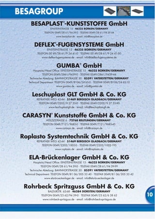

Die Besaplast® Kunststoffe GmbH ist auf die Herstellung und den Vertrieb von Fugenbändern und Wasserstopps spezialisiert, die für die Abdichtung von Bauwerksfugen in Betonbau eingesetzt werden. Das Unternehmen legt großen Wert auf Qualität, eigene Produktion und individuelle Entwicklung, was durch Patente und Marken unterstrichen wird. Die Wahl des richtigen Fugenbands ist entscheidend für die dauerhafte Dichtheit und die Vermeidung kostspieliger Reparaturen.


