
Empfohlen
Weitere ähnliche Inhalte
Was ist angesagt?
Was ist angesagt? (20)
Andere mochten auch
Andere mochten auch (20)
Ähnlich wie Components transistors
Ähnlich wie Components transistors (20)
Kürzlich hochgeladen
Kürzlich hochgeladen (20)
Components transistors
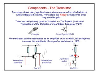
- 1. Components - The Transistor Transistors have many applications in electronics as discrete devices or within integrated circuits. Transistors are Active components since they provide gain. There are two primary types of transistor – The Bipolar (Junction) Transistor and the Unipolar or Field Effect Transistor (FET). The transistor can be used either as an amplifier or as a switch, for example to increase the amplitude of a signal or switch on an LED. Example Circuit Symbol (BJT) VCC + Gnd (0V) Input signal (sinewave) Output signal (sinewave) VCC + Gnd (0V) R LED Input signal (pulse)
- 2. Transistor manufactures use an alphanumeric code printed on the device as identification e.g. BC108, 2N3055, TIP31. It is necessary to refer to manufacturers data sheets to obtain lead information and ratings. The case style and packaging varies from miniature plastic TO92 or metal can TO18 for general purpose small signal types to TO220 and TO3 metal can for high power applications. Transistor Markings and Packaging TO-220 TO-3TO-92 TO-18
- 3. Small Signal Transistors Small signal transistors are used in circuits working on low signal amplitudes, high frequency etc and requiring high current gain eg pre-amplifiers, radio, display control. Most can operate up to 200mA providing the junction temperature is not greater than 75o C. Small signal transistors cannot disperse their heat due to the small case size and therefore some designs may require a heat sink to maintain a safe operating temperature.
- 4. Power Transistors In some cases it is necessary to pass a high current through a transistor in order to drive a load. This can result in heat being generated in the component. We must ensure that the component continues to operate to specification and no damage is caused as a result of this current. The heat generated is also known as power dissipation. Power transistors are designed to be mounted on a heat sink to remove heat generated and maintain a safe operating temperature.
- 5. Bipolar (Junction) Transistor Consists of two p-n junctions back-to-back in the same semiconductor. There are two possible arrangements n-p-n or p-n-p where a p-type or n-type semiconductor material called the base is contained between two thicker slices of the opposite material. p E C n n B Collector Emitter Base NPN B C E PNP n C E P P B C E B Collector Emitter Base Bipolar transistors have three terminals base, collector and emitter. The emitter always has an arrow indicating the direction of conventional current flow, (electron flow is opposite).
- 6. Function of a Transistor The bipolar transistor is used to amplify current A small input current is applied to the base terminal causing a much larger current to flow in the collector/emitter section. The amount of amplification is called the current gain and is known as the hFE and can range from 20 in power transistor to 400 in small signal transistors. Current Flow (conventional current) IC IB IC + IB IC IB hFE = or IC = hFE IB
- 7. The Darlington Pair Connecting a small signal transistor in series with a power transistor we can obtain a much larger current gain. This type of transistor is known as a Darlington or Darlington pair. Darlington transistors are ideal for interfacing low power electronic control circuits with motors, solenoids and relays. They are also used in digital control applications such as washing machines, drinks machines, dish washers. IC IB hFE = = hFE1 x hFE2 TR1 IB IC TR2 C B E
- 8. Transistor Circuits Activity 1. A transistor is stated as having a current gain of 150 what does this mean, give an example. 2. A transistor with a hFE of 200 is required to illuminate a 12v, 60mA lamp. Determine the base current required. 3. A 20µA current source is to be used with a transistor having an hFE ranging from 60 to 200. What would be the maximum collector current achievable for reliable operation. 4. It is required to drive a relay coil from a digital control circuit. If the relay requires 1 amp to operate the contacts and the digital control can only source 1mA state the required current gain and a most suitable type of transistor to be used, giving reasons.
- 9. Transistor Ratings Manufactures data sheets provide many details to enable the selection of the most suitable device for a particular situation. A selection of common parameters is shown below. VCE is the maximum collector/emitter voltage IC max current PTOT max power dissipation hFE minimum current gain fT the maximum operating frequency Type No Pol. Vce (V) Ic (max) PTOT hFE (min) fT (MHz) Case BC109 npn 25 200mA 750mW 240 150 TO-18 BC179 pnp 25 200mA 300mW 240 200 TO-18 TIP122 npn 100 5A 65W 1000 1 TO-220 BD135 npn 45 1.5A 12.5W 40@1.5A 160 TO-126 BD136 pnp 45 1.5A 12.5W 40@1.5A 140 TO-126 TIP31A npn 60 3A 40W 10@1A 3 TO-220 TIP32A pnp 60 3A 40W 25@1A 3 TO-220 2N3055 npn 60 15A 117W 20@4A - TO-3 TIP2955 pnp 100 15A 90W 20@4A - TO-218
- 10. Single Stage Transistor Amplifier (practical activity) This task is to build and test a transistor amplifier. You will gain experience in identifying and handling components, planning circuit layout and use of test equipment. circuit diagram The activity also forms part of your achievement criteria. VCC +12V Gnd 0V OUTIN TR1 R2 R1 R3 R4 C3 C1 C2
- 11. Transistor Switch (practical activity) This task is to build and test a light detector circuit using the transistor as a switch. The activity will enhance your experience of component types and their applications in electronics. VCC +12V Gnd 0V LDR R1 TR1 R2 Lamp circuit diagram The activity also forms part of your achievement criteria.