Datasheet Fluke A40B. Hubungi PT. Siwali Swantika 021-45850618
•
0 gefällt mir•302 views

Datasheet Fluke Precision Current Shunts.Informasi lebih detail hubungi PT. Siwali Swantika, Jakarta Office : 021-45850618 atau Surabaya Office : 031-8421264

Empfohlen
Empfohlen
Weitere ähnliche Inhalte
Was ist angesagt?
Was ist angesagt? (20)
Andere mochten auch
Andere mochten auch (11)
Ähnlich wie Datasheet Fluke A40B. Hubungi PT. Siwali Swantika 021-45850618
Ähnlich wie Datasheet Fluke A40B. Hubungi PT. Siwali Swantika 021-45850618 (20)
Mehr von PT. Siwali Swantika
Mehr von PT. Siwali Swantika (20)
Kürzlich hochgeladen
Kürzlich hochgeladen (20)
Datasheet Fluke A40B. Hubungi PT. Siwali Swantika 021-45850618
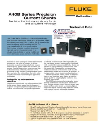
- 1. Technical Data A40B Series Precision Current Shunts Precision, low inductance shunts for dc and ac current metrology Intended for broad coverage of current measurement applications, the A40B Set consists of 14 low- inductance coaxial current shunts, leads, adapters and connectors, plus a rugged case for transit and storage. Together they cover a wide workload that includes electrical calibrators, electrical power standards, current sources, transconductance ampli- fiers, and more. You can purchase the entire set or individual shunts as required for your application and budget. Designed for top performance and ease of use The physical construction and the components used in the current shunts ensure that the frequency response is very flat (amplitude displacement error relative to dc resistance). The phase displacement A40B features at a glance Simplify calibration/verification of precision calibrators and current sources Shunts sized for currents from 1 mA to 100 A Usable from dc to 100 kHz 14 individual shunts with a 1, 2, 5 sequence over six decades of current Simple direct measurements, making ac/dc transfers unnecessary Stability typically better then ± 5.0 μΩ/Ω for one year Typical angular accuracy of better than ± 0.003° at 1 kHz The Fluke A40B Precision Current Shunts simplify and improve metrology for dc and ac current. Used to measure current from 1 mA to 100 A, the shunts ensure reliable and traceable results. For many applications, improved resistor technology enables you to make accu- rate ac current measurements in a single step, instead of using traditional, more complex ac/dc transfer methods. s simplify urrent. Used the shunts r at 100 kHz is small enough to be neglected in all but the highest accuracy measurements. Combined with excellent dc resistance stability, the shunts can be used to directly measure current through their full bandwidth. This simplifies precision ac cur- rent measurements, so the complex ac/dc transfer measurement process will no longer be necessary for many precision current measurement applications. The low phase shift error is critical for measure- ment of non sinusoidal wave shapes, as found in power quality or sampling digital wattmeter mea- surement applications. The A40B current shunts feature a radial design for high performance with minimum interference from external magnetic fields. The open design max- imizes air flow so the shunts have minimal power coefficient effects, enabling them to be used over a wide range of currents with stable resistance.
- 2. 2 Fluke Calibration A40B Series Precision Current Shunts An external cooling fan is not required. The shunts are the first commercially available product to feature this design. The 4-terminal design completely isolates measured voltage from extraneous current path resistance. Current does not flow in the voltage circuit, allowing you to measure with the highest accuracy. Optional adapters allow you to make connections with commonly used N connectors as well as LC connectors for high current applications. The 1 mA shunt includes an internal battery operated buffer amplifier to isolate the voltage measurement circuit from the current circuit. This enables you to use the shunt to make low cur- rent measurements at optimal voltage levels, while eliminating the effects of input impedance of the measurement device. Single step convenience In the past, complex ac/dc transfer techniques were required to verify ac current functions on calibra- tors. With current accuracy to 20 ppm and excellent dc resistance stability, the A40B shunts measure ac currently directly through their full bandwidth. For many applications, ac-dc transfer measurements will not be necessary. A simple measurement of the shunt, using a precision digital multimeter like the Fluke 8508A, can reduce measurement complexity by two thirds. Versatile solutions for many applications The shunts’ output voltage is nominal at 0.8 V, making them compatible with a wide range of devices including precision digital multimeters, ac-dc transfer standards, ac measurement standards, thermal voltage converters and sampling digital multimeters. Low inductance and low phase displacement make the A40B shunts an excellent fit for power measurement or digital sampling wattmeter mea- surement applications where phase accuracy and stability are critical. The wide current range allows verification of high current transconductance amplifiers. Report of traceable calibration included The A40B series comes standard with a report of traceable calibration including data. An optional ISO 17025 accredited report of calibration is available. Widest range available in commercial shunts The A40B shunts come in four sizes and a wide range of currents: Four fully enclosed shunts: 1 mA, 10 mA, 20 mA, 50 mA Five small radial shunts: 100 mA, 200 mA, 500 mA, 1 A, 2 A Three medium radial shunts: 5 A, 10 A, 20 A Two large radial shunts: 50 A, 100 A
- 3. 3 Fluke Calibration A40B Series Precision Current Shunts Electrical Specifications Absolute accuracy The following table shows the 1-year absolute accuracy specification stated at k=2, approximately 95 % confidence for the calibrated value. The specifications include 1-year stability, temperature effects over TCal ± 1 °C, and the measurement uncertainty of the calibrated value. Shunt Nominal Current Nominal Resistance (Ohms) Specification ± μA/A, TCal ±1 °C, ≤ 50 % RH1,2,3,5 DC 1 kHz 10 kHz 30 kHz 100 kHz 1 mA4 800 20 55 75 75 150 10 mA 80 20 26 26 26 26 20 mA 40 20 26 26 26 26 50 mA 16 20 23 23 23 23 100 mA 8 20 24 24 24 24 200 mA 4 20 26 26 26 26 500 mA 1.6 21 27 27 27 28 1 A 0.8 21 27 28 28 31 2 A 0.4 21 27 30 30 48 5 A 0.16 21 31 32 40 71 10 A 0.08 26 37 60 61 92 20 A 0.04 26 43 52 70 113 50 A 0.016 32 55 80 81 144 100 A 0.008 35 65 90 98 174 1 The measured current is determined from: I = (V/Rcalibrated) × (1 + (AC-DCcalibrated/1,000,000)); where AC-DCcalibrated is expressed in ppm. 2 Above 1 kHz interpolate the specification (si) between frequencies fupper and flower using: si = slower + (fi – flower) × (supper – slower) ÷ (fupper – flower) 3 Add 20 μA/A if relative humidity is outside specification limits. 4 1 mA specifications apply with the battery charger disconnected. 5 Specifications assume no loading effects due to the voltage-sensing device. See Output Voltage Measurement – Loading Effects in the operating information. Resistance Shunt Nominal Current Nominal Resistance (Ohms) Maximum Deviation from Nominal Resistance (± μΩ/Ω)2 Uncertainty of Cali- brated Value at 95 % Confidence (± μΩ/Ω) TCal ± 1 °C 12 Month Stability (± μΩ/Ω)1,2 Temperature Coefficient (± ppm/°C)2 Power Coefficient Multiplier (± ppm)2,3 1 mA 800 250 8.2 18 5 1 10 mA 80 250 6.8 18 2.5 1 20 mA 40 250 8.2 18 4.5 1 50 mA 16 250 8.3 18 4.5 1 100 mA 8 250 8.3 18 2.5 2 200 mA 4 250 8.6 18 3.5 4 500 mA 1.6 250 9.6 18 4.5 13 1 A 0.8 250 9.3 18 4.5 26 2 A 0.4 250 9.4 18 4.5 26 5 A 0.16 250 9.9 18 4.5 30 10 A 0.08 250 15 18 4.5 65 20 A 0.04 250 14 18 4.5 78 50 A 0.016 250 24 18 4.5 105 100 A 0.008 250 28 18 4.5 105 1 Stability specification combines long term change due to aging (permanent) and short term fluctuation due to humidity changes when shunts are used and stored within specified humidity limits. Add 20 ppm if humidity is >50 % RH). 2 Assume rectangular distribution when combining with other uncertainty contributions. 3 Calibrated resistance values include the effects of power coefficient at the nominal current. For currents other than nominal, apply the correction for power coefficient from: 4 TCal = ambient temperature at calibration. Correction = Power_Coefficient_Multiplier × 1 – IApplied INominal ( ) 2
- 4. 4 Fluke Calibration A40B Series Precision Current Shunts Maximum AC-DC difference Shunt Nominal Current Maximum AC-DC Difference (± ppm)1,2 1 kHz 10 kHz 30 kHz 100 kHz 1 mA3 53 72 72 150 10 mA 20 20 20 40 20 mA 18 18 19 30 50 mA 13 13 14 16 100 mA 14 15 17 27 200 mA 17 17 18 28 500 mA 17 17 17 21 1 A 17 19 19 23 2 A 17 22 22 44 5 A 23 24 34 69 10 A 28 55 58 98 20 A 37 51 80 150 50 A 47 75 79 180 100 A 60 90 120 300 1 Specifications indicate the maximum flatness deviation from dc, and include both measured AC-DC difference and the uncertainty of measurement. They are stated at k=2, approximately 95 % confidence. 2 Includes 1-year stability of the AC-DC difference. 3 Specifications for the 1 mA current shunt are for TCal ± 1 °C. Maximum overload current Shunt Nominal Current Maximum Current < 5 seconds1 Maximum Sustained Current2 Shunt Nominal Current Maximum Current < 5 seconds1 Maximum Sustained Current2 1 mA 3 mA 2 mA3 1 A 3.9 A 1.3 A 10 mA 150 mA 20 mA 2 A 5.5 A 2.2 A 20 mA 250 mA 40 mA 5 A 17 A 5.5 A 50 mA 450 mA 100 mA 10 A 24 A 11 A 100 mA 1.2 A 200 mA 20 A 42 A 22 A 200 mA 1.7 A 400 mA 50 A 95 A 55 A 500 mA 2.7 A 1 A 100 A 190 A 110 A 1 Longer than 5 seconds may cause permanent damage to the shunt. The output voltage may be considerably higher than 0.8 V. 2 Exceeding maximum sustained current may cause a resistance value step change. 3 1 mA shunt batteries should be fully charged to ensure performance at 2 mA. Typical phase displacement Typical Phase Displacement Shunt Nominal Current 1 kHz 10 kHz 100 kHz 1 mA to 200 mA < 0.001 ° < 0.006 ° < 0.060 ° 500 mA to 2 A < 0.003 ° < 0.030 ° < 0.300 ° 2 A to 20 A < 0.008 ° < 0.075 ° < 0.750 ° 20 A to 100 A < 0.013 ° < 0.125 ° < 1.250 °
- 5. 5 Fluke Calibration A40B Series Precision Current Shunts General specifications Dimensions (maximum) Shunt Value Height mm (inches) Width mm (inches) Overall Length1 mm (inches) 1 mA to 2 A 70 (2.75) 70 (2.75) 124 (4.9) 5 A to 20 A 130 (5) 130 (5) 210 (8.25) 50 A and 100 A 200 (7.9) 200 (7.9) 343 (13.5) 1 Includes input and output connectors; subject to change by component vendor. Physical/mechanical parameters Shunt Value Weight (maximum) kg (lb) Input Connector Output Connecctor 1 mA to 20 A 0.7 (1.6) Type-N (female) Type-N (female) 50 A and 100 A 3.4 (7.5) Type-LC (female) Type-N (female) Operating environment Temperature: 13 °C to 33 °C Calibration temperature (TCal) range: 18 °C to 28 °C Humidity range for best specification1,2 : ≤ 50 % RH Altitude: 0 m to 3,000 m 1 Resistance stability is affected by humidity, but changes are reversible. 2 If the shunts are calibrated outside this RH, stability specifications will be met as long as the shunts are stored and used at the same relative humidity ± 10 % RH. Storage and transit environments (for models other than the 1 mA current shunt) Temperature to avoid damage: -20 °C to 140 °C Temperature and humidity to maintain performance1 : 5 °C to 45 °C; 15 % to 80 % RH Non-operating altitude: 0 m to 12,000 m 1 Storage at extremes of temperature or humidity will cause a tem- porary change of shunt resistance by up to ± 20 ppm. When subse- quently stored or used within the limits of the operating environment, the shunts will recover to their original resistance value within 30 days. Additional 1 mA current shunt specifications Output resistance: 8 mΩ Maximum safe output current: 11 mA (e.g., 1 V output into 90 Ω) Maximum capacitive load: 800 pF Output voltage regulation: 15 ppm/100 pF Maximum output dc v offset: ± 100 μV (typical ± 25 μV) Typical error @ 1 MHz: < 2 % Battery specifications Battery size: AAA (44.5 mm x 10.5 mm) Battery technology: Nickel-Metal Hydride (NiMH) Number of batteries required: 8 (in 2 groups of 4) Nominal battery voltage: 1.2 V (4.8 V per group of 4) Typical battery capacity: 800 mAh Storage and transit environment to preserve the batteries Less than 90 days: -20 °C to 40 °C Less than one year: -20 °C to 30 °C Charging time (from fully discharged): 100 minutes Maximum operating time between charges Maximum output load (11 mA): 18 hours High impedance load: 24 hours Recommended cooling period: 100 minutes To prevent loss of battery capacity recharge at least twice per year.
- 6. 6 Fluke Calibration A40B Series Precision Current Shunts Ordering Information Models A40B/SET Complete set of 14 shunts with recommended connectors and adapters, leads and transit case. A40B-001MA 1 mA Current Shunt A40B-010MA 10 mA Current Shunt A40B-020MA 20 mA Current Shunt A40B-050MA 50 mA Current Shunt A40B-100MA 100 mA Current Shunt A40B-200MA 200 mA Current Shunt A40B-500MA 500 mA Current Shunt A40B-1A 1 A Current Shunt A40B-2A 2 A Current Shunt A40B-5A 5 A Current Shunt A40B-10A 10 A Current Shunt A40B-20A 20 A Current Shunt A40B-50A 50 A Current Shunt A40B-100A 100 A Current Shunt Options and accessories A40B-ADAPT/LC LC Male to LC Male adapter1 A40B-ADAPT/LCN LC Female to N Male inter-series adapter1 A40B-APAPT/SPADE LC Male to Spade Terminal Adapter A40B-LEAD/4MM N to 4 mm double banana connector2 A40B-LEAD/N N male to N male lead1 A40B-CASE Fiberglass Transit Case 1883673 UKAS Accredited Calibration 1 A quantity of one of this accessory item is included in the A40B/SET 2 A quantity of two of this accessory item is included in the A40B/SET Specialized accessories (recommended when calibrating A40B series shunts) A40B-CAL/LC High current adapter to connect two shunts in series for measurement (LC to LC) A40B-CAL/N Low current adapter to connect two shunts in series for measurement (N to N) ommended transit case. apter1 or2 Fluke Calibration PO Box 9090, Everett, WA 98206 U.S.A. Fluke Europe B.V. PO Box 1186, 5602 BD Eindhoven, The Netherlands For more information call: In the U.S.A. (877) 355-3225 or Fax (425) 446-5116 In Europe/M-East/Africa +31 (0) 40 2675 200 or Fax +31 (0) 40 2675 222 In Canada (800)-36-FLUKE or Fax (905) 890-6866 From other countries +1 (425) 446-5500 or Fax +1 (425) 446-5116 Web access: http://www.flukecal.com ©2008-2012 Fluke Calibration. Specifications subject to change without notice. Printed in U.S.A. 3/2012 3381946B D-EN-N Pub_ID: 11478-eng, rev 03 Modification of this document is not permitted without written permission from Fluke Calibration. Fluke Calibration. Precision, performance, confidence.™