
Empfohlen
Weitere ähnliche Inhalte
Was ist angesagt?
Was ist angesagt? (20)
Andere mochten auch
Andere mochten auch (20)
Ähnlich wie Power supply
Ähnlich wie Power supply (20)
Kürzlich hochgeladen
Kürzlich hochgeladen (20)
Power supply
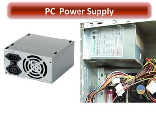
- 1. PC Powe r Supply
- 2. Power Supply Block Diagram of Power Supply The Power Supply Converts AC to DC and regulates the output voltage to a value required by the load
- 3. A T Standard Advanced Technology Standard
- 4. A T Standard Output Voltages Standard Color Pin Voltage P8-1 +5 Orange P8-2 +5 Red P8-3 +12 Yellow P8-4 -12 Blue P8-5 Ground Black P8-6 Ground Black Standard Color Pin Voltage P9-1 Ground Black P9-2 Ground Black P9-3 -5 White P9-4 +5 Red P9-5 +5 Red P9-6 +5 Red
- 6. Power Supply • A power supply (sometimes known as a power supply unit or PSU) is a device or system that supplies electrical or other types of energy to an output load or group of loads. The term is most commonly applied to electrical energy supplies. At the motherboard At the Cable • The most common computer power supply is built to conform with the ATX form factor. This enables different power supplies to be interchangeable with different components inside the computer.
- 7. A T X Connector Standard • The ATX (for Advanced Technology Extended) form factor was created by Intel in 1995. It was the first big change in computer case and motherboard design in many years. • ATX overtook AT completely as the default form factor for new systems. ATX addressed many of the AT form factor's annoyances that had frustrated system builders. AT POWER CONNECTOR
- 8. A T X Power Connector - ATX Power Supply connector - Typical wattages range from 200 W to 500 W - There are also other, smaller connectors, most of which have four wires: two black, one red, one yellow. “each black wire is a Ground, the red wire is +5 V, and the yellow wire is +12 V.”
- 9. A T X ATX Motherboard Connectors Pin Voltage Standard Color 1 + 3.3 Orange 2 + 3.3 Orange 3 Ground Black 4 + 5 Red 5 Ground Black 6 + 5 Red 7 Ground Black 8 + 5 Gray 9 + 5 Purple 10 + 12 Yellow Pin Voltage Standard Color 11 + 3.3 Orange 12 - 12 Blue 13 Ground Black 14 PS_On Green 15 Ground Black 16 Ground Black 17 Ground Black 18 - 5 White 19 + 5 Red 20 + 5 Red At the motherboard At the cable
- 10. B T X Connector Standard • In 2003, Intel announced the new BTX standard, intended as a replacement for ATX. BTX (for Balanced Technology Extended) is a form factor for PC motherboards, originally slated to be the replacement for the aging ATX motherboard form factor in late 2004 and early 2005. At the motherboard
- 11. B T X Connector Pin Designation Pin Signal Description 1 +3.3 VDC 2 +3.3 VDC 3 COM Ground 4 +5 VDC 5 COM Ground 6 +5 VDC 7 COM Ground 8 PWR_OK Power good - indicate that VDC voltages are in range. 9 +5 VSB Standby voltage 10 +12 VDC
- 12. B T X Connector Pin Designation Pin Signal Description 11 +12 VDC 12 +3.3 VDC 13 +3.3 VDC 14 -12 VDC 15 COM Ground 16 PS_ON# Active low. TTL compatible (0.1-0.8V low; 2.0 high?). When low - DC outputs are enabled. When high - power supply should not deliver DC current. 17 COM Ground 18 COM Ground 19 COM Ground 20 N/C 21 +5 VDC 22 +5 VDC 23 +5 VDC 24 COM Ground
- 13. B T X/ATX/AT HDD and FDD Power Connector Pin Designation Pin Voltage Color 1 + 12 Yellow 2 Ground Black 3 Ground Black 4 + 5 Red
- 14. Question • Can I fit an ATX mainboard in an AT case? - Not really. An AT case and AT power supply can neither power up nor house a new ATX mainboard. ATX and AT are two different form-factors. The AT case was designed before ATX. Most of the computer cases built before late 1996 were AT form-factor. For over 10 years, from about 1985 to 1997, the AT form-factors, founded by the original IBM PC-AT, provided the standard for 90% of the PC industry. Today, the majority of new systems ATX form-factor. The ATX is also known as the Extended AT form-factor.
- 15. Choosing a Power Supply Why Weight Matters? The more appropriate question is why size matters. The weight of a power supply is directly related to the quantity, quality, and size of the material (thus cost) used to build the power supply.
- 16. Choosing a Power Supply • Conclusions This brief study clearly confirms an empirical knowledge: the quality of a power supply can be estimated by its weight. - The very simple and easy way for ordinary PC users to estimate and compare the quality of a power supply.
- 17. Identifying Defective Power Supply(Dead set) • For AT Power Supply Turn on the main power switch(mechanical) and measure the presence of the output voltage (±12V and ± 5V) using a voltmeter. If a voltmeter is not available, just observe the functionality of the cooling fan. • For ATX and BTX Power Supply Simply short the Ps_On terminal and observe the cooling fan. If the fan works, the power supply is good. You can measure the output voltage of each terminal and compare the reading to the specified values. • Replacement of a known good Power Supply is the last approach for confirmation.