Fluid motion in the posterior chamber of the eye
•
2 gefällt mir•3,246 views


Empfohlen
Weitere ähnliche Inhalte
Was ist angesagt?
Was ist angesagt? (20)
Andere mochten auch
Andere mochten auch (20)
Ähnlich wie Fluid motion in the posterior chamber of the eye
Ähnlich wie Fluid motion in the posterior chamber of the eye (15)
Kürzlich hochgeladen
Kürzlich hochgeladen (20)
Fluid motion in the posterior chamber of the eye
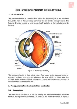
- 1. FLUID MOTION IN THE POSTERIOR CHAMBER OF THE EYE. 1. INTRODUCTION. The posterior chamber is a narrow chink behind the peripheral part of the iris of the lens, and in front of the suspensory ligament of the lens and the ciliary processes. The Posterior Chamber consists of small space directly posterior to the Iris but anterior to the lens. Figure 1: Human eye anatomy The posterior chamber is filled with a watery fluid known as the aqueous humor, or aqueous. Produced by a structure alongside the lens called the ciliary body, the aqueous passes into the posterior chamber and then flows forward through the pupil into the anterior chamber of the eye. 2. The equations of motion in cylindrical coordinates: 2.1 Assumption: The main goal of this work is to find the velocity and pressure distribution profiles to the fluid moving in vitreous chamber. To construct the model of the flow of aqueous Page 35 of 43
- 2. fluid in the vitreous (posterior) chamber of the eye let us consider following assumptions: The aqueous fluid is Newtonian and incompressible fluid Asymmetric flow The height of the chamber is small compared to the radial length Neglect the flow in the region of the pupil Steady-state analysis Rigid iris Figure 2: Simple model for the chamber Consider equations of motion: the Equation of Continuity and Navier - Stokes Equation. Here we work in the cylindrical coordinates. Hence we use the equations for the cylindrical coordinates. Where, We consider geometry of the domain: Ri r Ro . Let's consider cylindrical coordinates z, r , with corresponding velocity components u z , u r , u . According to the geometry of the system, there is no motion in u φ direction and also the velocity is not a function of φ, i.e. u 0 and 0 Also, with the hypothesis of having incompressible fluid ( constant) and considering the system in the steady-state (nothing is a function of time), the equation of motion will be reduced to the followings: u z 1 rur 0 (1) z r r Page 36 of 43
- 3. This is called The Equation of Continuity. And The Navier Stokes Equations: u r u P 1 rur 2 u r ur uz r r r r z 2 (2) r z r u z u P 1 ru z 2 u z ur uz z r r r z 2 (3) r z z 2.2 Order of magnitude and simplification of the equation: Characteristic dimensions: a) Characteristic velocity in the r-direction: U b) Characteristic dimension in the r-direction: L Ri Ro c) Characteristic dimension in the z-direction: H If we denote the order of magnitude as O (.), we will have the followings: O(u r ) U u U O r r L Now from the continuity equation we have: u 1 rur U O z O z r r L UH O(u z ) L Simplification of the equations in the r-direction: 1 ru r U 1 O r r r L2 2u U 2 O 2z 2 z H Since H << L we can neglect the expression (1) in comparison to expression (2). So the equation in the r-direction would be u r u r P 2ur ur uz 2 r z r z Page 37 of 43
- 4. Simplification of the equations in the z-direction: 1 u z UH 1 1 O r r r r L . L2 2 u z UH 1 2 O 2 z . L H2 Again since H << L we can neglect the expression 1 in comparison to expression 2 .So the equation in the z-direction reads u z u P 2u ur uz z 2z r z z z Scaling and comparing the equations in the r and z direction Knowing the order of magnitude of the expressions in r and z direction, we make the equations dimensionless as follows: U2 * u r * u r * P P * U 2u * u r * u * * o . * 2 *2r r z L r H z z L U2 * u * u * P P * U 2u * u r * u * * o . * 2 *2z r z z z L z H z z L H Where, 1 , P Po P * and Po will be specified later. L Then we have, UH * u r * * u r * H 2 Po P * 2 u r * ur uz * . r * z UL r * z *2 UH * u * u * H 2 Po P * 2u * 2 ur * u * * z z . * *2z r z UL z z z According to the above equations, we can find the proper scaling for Po by balancing with the viscous terms. This leads to UL Po H2 Page 38 of 43
- 5. Now, if we multiply the equation of motion in the z-direction by , you can neglect the terms with 2 & 3 and we will end up with P * 0 z * This suggests that P is not a function of z. Therefore, pressure is just a function of r, i.e. P f r 2.3 Further simplification in r-direction: By neglecting the nonlinear part of the equation of motion in the r-direction and here our problem is a type of lubrication theory, so we have: UH Re Therefore we can write: u r * u r * P * 2 u * Re u r* u * * . * *2r r * z r z z Now if .Re 1 , then we can neglect the non-linear part in the equation of motion. Since the Reynolds number for the aqueous humor is approximately 10 3 [1], then the above condition holds. Therefore, we can reduce the equation of motion in the r- direction to the following: P 2ur (1) r z 2 Integrating the equation (1) with respect to z, we will reach 1 P 2 ur z c1 z c 2 2 r We can find the constants c1 and c 2 , using the no-slip conditions u r ( z 0) u r ( z H ) 0 H p c1 2 r c2 0 Page 39 of 43
- 6. Substituting the constants in the equation of motion we have H P z z 2 u r ( z, r ) (2) 2 r H H Here for simplicity we consider the height H to be constant in our calculation. For H hr , the calculation process is similar. Now, the only undetermined term in the velocity profile is the pressure distribution which will be calculated as follows: 2.4 Pressure distribution: Integrating the continuity equation with respect to z, from 0 to H, we will have u z 1 ru r H H z 0 dz 0 r r dz 0 1 ru r H uz uz dz 0 zH z 0 0 r r Using the no-slip conditions uz zH uz z 0 0 We will end up having 1 ru r H r r dz 0 0 1 H r u r dz 0 r r 0 Since r 0 H r u r dz 0 r 0 H r ur dz c 0 Where, c is a constant. Page 40 of 43
- 7. Since r 0 H c u dz r 0 r Substituting u r into the equation and computing the integral, we will get H 3 P c ( ) (3) 12 r r To find the constant c, we integrate the equation as follows: H3 Let's call, A 12 P0 R0 dr A dp c Pi Ri r R0 A( P0 Pi ) c(ln ) Ri A( P0 Pi ) c R ln 0 Ri Calculating the indefinite integral of equation (3), we get the pressure distribution: P0 Pi P(r ) ln r k R0 ln( ) Ri To find the constant k, we know that P(r Ri ) Pi and therefore: P0 P kP i i ln( Ri ) R0 ln( ) Ri P0 Pi r P(r ) ln( ) Pi (4) R Ri ln( 0 ) Ri Page 41 of 43
- 8. 2.5 Velocity Profile: Substituting the derivative of the pressure distribution in equation (2) for velocity profile, we get H 2 1 P0 Pi z 2 z ur ( z , r ) [( ) ] (5) 2 r ln( R0 ) H H Ri Here one can make the calculation more accurate by considering the height of the posterior chamber to be a function of r rather than being constant. In this case, based on the model in Figure 1, one may substitute H in equation (3) with h(r ) which has the following equation: h(r ) m.r k Where, k h0 R0 m hi h0 (6) m Ri R 0 Then, following similar procedure one can get the pressure distribution and velocity profile. 3. CONCLUSION: Pressure distribution: The highest pressure is at the radius Ri where P(r Ri ) Pi . As we move along the r-direction toward the pupil, the pressure drops logarithmically P Pi r by 0 ln( ) . If we increase P0 Pi (keeping the values Ri and Ro constant), we R Ri ln 0 Ri will have a larger pressure drop in the posterior chamber. Knowing the pressure distribution is very important in studying the glaucoma. In the severe glaucoma (closed-angle glaucoma), eye pressure builds up rapidly when the drainage area (trabecular meshwork) suddenly becomes blocked, in this case the high amount of pressure in the posterior chamber results in increase of the fluid pressure within the inner eye , which can damage the optic nerve and lead to vision loss. Page 42 of 43
- 9. 3.1 Velocity profile: The aqueous humor has the following characteristics Density 1000kg.m 3 Viscosity 7.5 10 4 kg.m 1 .s 1 Characteristic length scale H 2 10 6 m From the equation (5) for the velocity profile, one can notice that the highest velocity is H at r Ro and z , i.e. exactly at the entrance to the pupil. Based on [1], the 2 maximum velocity of the aqueous humor is 1.01m.s 1 , which is about 3rd orders bigger than the velocity in the anterior and posterior chambers. 4. REFERENCE: [1] Jeffrey J. Heys, Victor H. Barocas and Michael J. Taravella; Modeling Passive Mechanical Interaction between Aqueous Humor and Iris, Journal of Biomechanical Engineering, Dec. 2001, vol. 123(6), p.p. 540-7. [2] Repetto, R., Tatone, A., Testa, A. and Colangeli, E. 2011. Traction on the Retina Induced by Saccadic Eye Movements in the Presence of Posterior Vitreous Detachment. Biomech. Model. Mechanobiol., vol. 10, pp. 191-202, doi:10.1007/s10237-010-0226-6. [3] Repetto, R., Siggers, J. H. and Stocchino, A. 2010. Mathematical model of flow in the vitreous humor induced by saccadic eye rotations: effect of geometry. Biomech. Model. Mechanobiol., vol. 9, pp. 65-76. [4] Stocchino, A., Repetto, R. and Siggers, J. H. Mixing processes in the vitreous chamber induced by eye rotations. 2010. Phys. Med. Biol, vol. 55, pp. 453-467. [5] R. Byron Bird, Warren E. Stewart and Edwin N. Lightfoot. Transport Phenomena. 2nd edition. Page 43 of 43