Porous carbon in Supercapacitor Shameel Farhan 090614
1. Porous Carbon in Supercapacitors
-A review
Submitted to
Prof. Yani Zhang
School of Materials Science,
NPU, Xi’an, China
Prepared by
Shameel Farhan
PhD Student
(Carbon foam core sandwich structures)
Student ID 2013410005
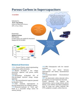
Historical Overview
1950s- General Electric started experimenting
using porous carbon electrodes.
1957-Becker developed a low voltage
electrolytic capacitor with porous carbon
electrodes.
1966-Researchers at Standard Oil of
Ohio developed electrical energy storage
apparatus.
1970- The electrochemical capacitor patented
by Donald L. Boos.
1971-NFC marketed supercapacitor to
provide backup power for computer memory.
1978-Panasonic marketed its "Gold caps”
brand as a successful energy source for
memory backup.
1982-PRI Ultracapacitor with low internal
resistance.
1991- Line was drawn between
supercapacitor and battery electrochemical
behavior.
1994-Electrolytic-Hybrid Electrochemical
Capacitor.
2007-An electrostatic carbon electrode with a
pre-doped Li-ion electrochemical electrode.
Current Research- To improve the
characteristics, such as energy density, power
density, cycle stability and reduce production
costs by using new carbon materials like
CNTs, graphene, aerogels, carbon foam etc.
A capacitor differs from a battery in that it can
store a higher amount of energy, but for a
shorter period of time. This allows a
supercapacitor to be used in applications that
require larger amount of energy in repeated
bursts (for example, a camera flash). Batteries,
however, supply the bulk of energy in most
devices since they can store and deliver
energy over a slower period of time.
If you handle your
super capacitors
carefully, you will die
before they
do...Seriously!
What everyone wants
is a device that can
store a lot of energy
and charge or
discharge quickly.
2. Fig.1 Standard lithium ion battery vs supercapacitor.
Overview of Supercapacitors
Electrochemical capacitors, electric double-
layer capacitor, supercondenser, pseudo
capacitor, electrochemical double layer
capacitor and ultra-capacitor, are
electrochemical energy-storage devices
characterized by high power densities and
exceptional cycle lifetime required for handy
electronics to heavy Industrial applications
including hybrid vehicles. Performance of a
supercapacitor depends on the surface
area/cm of electrode, electrolyte and the
separator used. Unlike conventional
capacitors, supercapacitors do not have a
dielectric, an electrical insulator that can be
polarized with the application of an electric
field. Instead, the plates of a supercapacitor
are filled with two layers of the identical
substance. This allows for separating the
charge. Materials used in making
supercapacitors are made from powdered,
activated carbon. Various institutions have
researched the possibility of using carbon
nanotubes. Certain polymers as well
as graphene, a material made of tightly
packed carbon atoms, are also used for
production. By contrast, while
supercapacitors have energy densities that are
approximately 10% of conventional batteries,
their power density is generally 10 to 100
times greater. This results in much shorter
charge/discharge cycles than batteries.
Additionally, they will tolerate many more
charge and discharge cycles than batteries.
Many capacitors used in audio circuits have
capacitances such as 470uf or 680uf (micro
farads). Capacitors used in high frequency
RF applications can be as small as 1pf (pico
farad). The farad is a measure of capacitance
(or storage capacity).
Basic Design
Principle construction of a supercapacitor is
shown in figure 2. Ions are separated from the
electrolyte by a charging current, and are
propelled toward their respective electrodes.
The membrane serves to separate the ions so
that a net charge separation can be maintained.
Notice that the ions on the electrode surface
3. are neutralized (save for a residual dipole
field) by the opposite charge attracted to just
below the surface of the electrode. This dual
surface layer is called an electric double layer.
All other parameters being equal, the number
of ions stored is proportional to the surface
area of the electrodes. Energy storage of a
capacitor is proportional to the amount of
charge stored, so a tenfold increase in
capacitance will require new electrodes that
are highly conductive (so large power levels
can be generated) and provide more surface
area than conventional supercapacitors.
Fig. 2 Basic supercapacitor; 1. Power source, 2.
Collector, 3.polarized electrode, 4. Helmholtz
double layer, 5. Electrolyte having positive and
negative ions, 6. Separator.
Applications
They are often used in filtering applications,
coupling or decoupling applications, or AC-
DC smoothing applications (there are some
large caps in standard AC-DC power supply
that acts to smooth out the ripple on the line),
hybrid vehicles and electric vehicles, self-
powered equipment powered by human
muscle, mechanically powered flashlight,
enhancing performance for portable fuel cells,
such as generators, and improving the
handling of batteries.
Classification
Supercapacitors are divided into three
families, based on electrode design:
Double-layer capacitors –
with carbon electrodes or derivates
with much higher electrostatic double-
layer capacitance than electrochemical
pseudo capacitance
Pseudo capacitors – with metal
oxide or conducting
polymer electrodes with a high
amount of electrochemical pseudo
capacitance
Hybrid capacitors – capacitors with
asymmetric electrodes, one of which
exhibits mostly electrostatic and the
other mostly electrochemical
capacitance, such as lithium-ion
capacitors
New Research
Now researchers at UCLA have used a
standard DVD writer to make such electrodes.
The electrodes are composed of an expanded
network of graphene that shows excellent
mechanical and electrical properties as well
as exceptionally high surface area.
The process is based on coating a DVD disc
with a film of graphite oxide that is then laser
treated inside a DVD writer to produce high-
quality graphene electrodes. Graphite oxide is
a compound of carbon, oxygen, and hydrogen
made by treating graphite with sulfuric and
phosphoric acids combined with potassium
permanganate, an extremely strong oxidizer.
When graphite oxide is placed in a basic
solution, it exfoliates into monomolecular
layers with a graphene-like structure. These
layers were then collected on an ordinary
4. DVD disc. The disk was then written on, a
number of passes being made.
Fig. 3 UCLA researchers develop new technique
to scale up production of graphene micro-
supercapacitors.
The action of the 5 milliwatt IR laser on the
graphite oxide was to reduce the material,
thereby producing isolated but intertangled
graphene monolayers. The surface area of the
resulting electrodes was 1,520 square meters
per gram - about a third of an acre, and 3-5
times the surface area of activated carbon
electrodes. Graphene's intrinsic surface area is
2,630 square meters (about two thirds of an
acre) per gram.
The UCLA research team investigated several
different types of supercapacitor chemistry
using the laser scribed graphene electrodes.
They found the supercapacitors were
surprisingly robust against flexure, surviving
thousands of folds with no significant change
in capacitance. Their highest energy storage
supercapacitor was based on using the ionic
liquid 1-ethyl-3-methylimidazolium
tetrafluoroborate as the electrolyte. The
supercapacitor exhibited a capacitance of 276
Farads per gram, and an operating voltage of
4 volts. This corresponds to an energy density
of over 600 watt-hours per kilogram, or about
four times that of lithium-ion batteries. In
practice, the energy density will be smaller,
owing to support structures, but such
supercapacitors should be able to give
lithium-ion batteries a run for their money.
Fig. 4 Schematic showing the structure of laser
scribed graphene supercapacitors created by
UCLA researchers.
The researchers didn't stop there, though.
They began to play around with electrodes.
Kaner said, "We placed them side by side
using an interdigitated pattern, akin to
interwoven fingers. This helped to maximize
the accessible surface area available for each
of the two electrodes while also reducing the
path over which ions in the electrolyte would
need to diffuse. As a result, the new
supercapacitors have more charge capacity
and rate capability than their stacked
counterparts."
A few years ago, a group of researchers at the
Lawrence Berkeley National Laboratory
began working on creating micro-
supercapacitors. Using micro fabrication
methods similar to those which are already
being used to create microchips for electronic
devices, these researchers etched electrodes
of monolithic carbon film into a substrate of
conductive titanium carbide. The result was
micro-supercapacitors that had an energy
storage density at least twice as much as
existing supercapacitors.
5. Fig. 5 Berkeley Lab chemist John Chmiola is
developing a new breed of micro-supercapacitors.
Overcoming the Limitations of
Supercapacitors
Like a battery, a standard capacitor stores
electrical energy. Whereas a battery can both
produce and store electrons, a capacitor can
only store them. And although a battery can
dump its charge slowly through the course of
hours, a capacitor dumps its charge in mere
seconds.
Supercapacitors also have a low energy
density and can only hold 1/5th to 1/10th the
energy of a standard battery. Because of the
organic electrolyte used in supercapacitors,
the fast energy discharge of a supercapacitor
is much higher than that of a battery.
Supercapacitors are low voltage devices: in
order to achieve a practical working voltage,
several need to be strung together. And at
present, mass production of supercapacitors
has not been something that is cost effective.
For example, if you wanted to use a
supercapacitor to charge your laptop now,
you might have to spend hundreds of dollars
on dozens of supercapacitors. When
connected together, these series of
supercapacitors would create a laptop that
would no longer be very mobile.
Because of these limitations, using
supercapacitors in our home electronics and
mobile devices is not yet feasible. The
wonders of graphene seem to know no
bounds. Not only is it one of the strongest
materials known, is both highly conductive
and piezoelectric, it can generate
electricity from flowing water and now it is
being used to make better supercapacitors.
Porous carbon as electrode
material in supercapacitors
In principle, any pore size can be adjusted and
inserted into carbon, ranging from ultra-
micropores to μm-sized macropores. It has
been shown many times that the different
approaches are largely compatible with each
other, with the consequence that many
hierarchical materials could be designed over
the last few years. The biggest challenge for
carbon materials with well-defined pore sizes
in supercapacitor applications is the reduction
of price. No material could compete with the
very low costs and the scalability of activated
carbons so far. Graphenes and carbon onions
show better conductivities. The pore sizes of
templated carbons are more narrowly
distributed. Aerogels and fibers can directly
be fabricated into the desired electrode shape.
VA-CNTs are orientated and perfectly
connected to a current collector.
Electro sorption of electrolyte molecules on
the surface of a porous carbon material is the
key process in supercapacitors. High power
densities can be accomplished if the
electrolyte has fast access to the surface of the
electrode material. This can be ensured either
by lowering the particle size of the carbon
material down to the nanometer scale or by
introducing internal porosity. The size,
geometry, and distribution of these pores
6. Fig. 6 Energy density of carbon materials with different pore size depends on the potential window (A).
Optimal pore size increases with increasing operating voltage window (B) and passes a maximum (C).
significantly influence the final performance
of the supercapacitor device. The pore size
distribution should be span over micropore
scale (dpore < 2 nm) and the mesopore scale (2
nm < dpore < 50 nm). There is an optimal
micropore size, which is different for each
electrolyte system and at different voltage
windows. Pore size distribution and
uniformity are important for increasing the
capacitance. Various techniques like
activation, templating and etching etc are
used to tailor the required pore size
dictribution.
Tailoring microporisity in electrodes
The capacitance (C) of a supercapacitor
electrode depends on the electrode specific
surface area (A), and the distance (d) between
the adsorbed ions and the electrode surface as
shown in equation 1.
C = (εA)/d (1)
The dielectric constant (ε) is set by the used
electrolyte. The values of A and d are
significantly influenced by the size of the
micropores. An “optimal” micropore size is
7. not easily available because the actual energy
density also depends on the ion size and
operating voltage window
At a given pore size, the maximal energy
density increases with increasing cell voltage
and saturates at high voltages when no
additional charge can be accommodated
within the pore (Fig. 6A). This saturation
energy density increases (high voltages) when
the pores get larger since more charge can be
stored. Therefore, at high voltages large pores
are preferable (Fig. 6B). At low voltages
however, the energy density is smaller for
large pores because an electro-neutral zone is
formed in the centre of the large pore, which
does not contribute to stored charge (Fig. 6C).
Synthesis of materials with very narrow pore
size distributions (PSD) is encouraged if the
capacitance performance should be optimized.
Experiments such as small-angle neutron
scattering and nuclear magnetic resonance
investigations (NMR) are used to directly
probe the ion adsorption and electrosorption
in microporous carbons. All of these studies
impressively show the importance of
uniformly adjusting the micorpore size in
supercapacitor electrodes with low dispersity.
Templating is the method of choice if
materials with uniform and ordered pore
systems should be synthesized. This strategy
is faced with the accusation of being
expensive and badly up-scalable, but its
academic benefit is non-questionable. Again,
these materials are currently of outstanding
importance since questions on electrolyte–
carbon interaction or the principle influence
of pore size/geometry/connectivity on
supercapacitor performance need to be
answered. The variety of templates is
versatile and carbons with uniform micropore
sizes are derived from different zeolite
templates (e.g. Y, X13, beta, L, ZSM-5). If
the zeolite channels are 3D-connected the
replica carbon is even ordered. The specific
surface areas of these carbons even exceed
4000 m2
g−1
. Activation of carbonaceous
sources is a comparably low-price technique
to introduce porosity. Activated carbons are
obtained from the carbonization and
activation of resources such as coals, peat,
special woods, coconut shells and synthetic
organic polymers etc. They are amorphous
and contain nitrogen or oxygen. The main
activating agents are carbon dioxide, steam,
potassium hydroxide, zinc chloride and
phosphoric acid. All activation processes
differ in the fraction of pore sizes they create.
This is generally observed, since all these
agents act as dehydrating agents, stabilizing
the carbon structure, giving higher carbon
yields. The best of them exceed capacitances
of 300 F g−1
in aqueous electrolytes. But
activation is not only suitable for natural
carbon resources. Recent attempts use natural
resources such as fungi as carbon precursors.
Hierarchical carbons derived from KOH
activation of these sources show surface areas
exceeding 2000 m2
g−1
and very narrow
micropores.
Tailoring small mesoporosity in
electrodes
Templating can be subdivided into soft- and
hard-templating. The hard templates, mostly
nanoscaled silica materials, are infiltrated
with carbon precursors (e.g. sucrose, furfuryl
alcohol, phenolic resin, pitches, acetonitrile),
which are then polymerized and finally
carbonized. In most instances, subsequent
removal of the template is necessary. The
soft-templating approach uses surfactants as
structure-directing agents and carbon
precursors (primarily based on resin) that
interact with the surfactant and assemble
around the formed micelles. Varying the
surfactant/precursor ratio gives access to
different mesostructures. The size of the
8. carbon precursor and its pre-polymerization
degree determine the final pore size. In
addition, the pore symmetry (cubic,
hexagonal, wormlike) as well as the pore
connectivity can be controlled leading to
advanced ion transport properties.The final
pore size can further be changed if additional
activation steps are conducted. Templated
carbons are primarily amorphous and often
badly conductive. In consequence, conducting
additives such as nanotubes or carbon black
are added if these materials are applied in
supercapacitor applications.
Tailoring large mesopore and
macroporisity
Carbons with large mesopores or even
macropores are accessible using colloidal
templates such as silica nanoparticles. These
particles are either commercially available or
can be synthesized using emulsion, spray
pyrolysis or Stöber approaches. Carbon
precursors, such as resins, acrylonitrile,
pitches, or carbon hydrates first polymerize
and then carbonize around the sol template
structure followed by dissolution of the
template. The final pore size is mainly
determined by the silica particle size. Larger
mesopores can be introduced if mesocellular
silica foams (MCFs) are utilized as templates.
Important structural properties such as pore
sizes and the degree of graphitization are
precisely controllable by the elevated
synthesis temperature. These materials show
specific capacitances as high as 240 F g−1
in
aqueous electrolytes. This technique is
useable for template particles of different
sizes providing a versatile access to carbons
of different mesopore sizes with different
amounts of additional micropores.
Macroporous carbons are also synthesized
using silica or polymer opal templates giving
especially three-dimensional ordered carbon
replicas. These materials show capacitances
as high as 120 F g−1
in organic electrolytes.
Carbon aerogels are a class of macroporous
open cell foams with very low mass densities
and large pore volumes that are derived by
sol–gel chemistry. A molecular precursor,
often based on resorcinol, is cross-linked into
a gel via polymerization. The resulting
hydrogel displays a three-dimensional
network of interconnected nanometer-sized
particles. This material has to be dried under
particular conditions such as supercritical
drying or freeze drying. The arrangement and
connectivity of the primary particles are
influenced by catalyst parameters and
reaction conditions and therefore dictate the
final properties of the aerogel such as electric
conductivity, pore size, surface area, or pore
volume. Aerogels often exhibit large, broadly
distributed and flexible macropores,
accompanied by large pore volumes. The
latter can be a drawback in supercapacitor
applications because the low density limits
the volumetric capacitance/energy density
which is a general disadvantage of electrode
materials containing large pores. An
advantage of this sol gel approach however is
the simple access to shaped materials such as
monoliths or thin films avoiding the
additional necessity for current collectors in
the final supercapacitor device. Hierarchical
aerogels are of certain relevance as well and
are most often synthesized by combining this
approach with templating or activation
processes.
In the light of cost reduction it is straight-
forward to synthesize porous carbons from
abundantly available natural bio-resources or
waste products that accumulate during
agricultural production. The carbonization
and subsequent chemical activation of wastes
such as cow manure and pulp-mill sludge
yielded, depending on activation steps and
temperature, broadly distributed meso-
/macroporous carbons with surface areas up
9. to 700 m2
g−1
and pores around 25–100
nm. In recent years, the hydrothermal
carbonization of natural carbon precursors
was established as a very useful route for the
production of carbon materials. This route can
be applied to different types of organic
materials such as algae, wood sawdust, starch,
or cellulose. Nitrogen-doping of the resulting
carbons can be achieved by using amino-
containing biopolymers such as chitosan
or D-glucosamine increasing the
conductivity and therefore the performance in
supercapacitor applications. Monolithic,
flexible, sponge-like, carbonaceous aerogels
have been synthesized applying a
hydrothermal process to water melons. These
materials have pores of approximately 45 nm
and can be loaded with metal oxides resulting
in high capacitive materials. The presence of
heteroatoms within these materials has
several advantages. Oxygen-rich carbons
made from seaweeds, only possess low
surface area around 200 m2
g−1
but
comparatively high capacitance due to the
oxygen functionalities that act in pseudo
faradic charge/transfer reactions. Carbon
nanotubes with high aspect ratios that are
arranged perpendicular to a substrate are
known as vertically aligned carbon
nanotubes. Their porosity matches with the
distance between the single (but multi-walled)
nanotubes and is therefore well-defined and
controllable with the synthesis parameters.
They can be synthesized by catalytic thermal
chemical vapor deposition (CVD) either
under atmospheric or vacuum conditions
using a variety of carbon precursors such as
acetylene, ethylene, or alkanes.
External surface area and inter-
particular porosity
As per definition a surface curvature is called
a pore if its cavity is deeper than wide. One
straightforward approach is to lower the
particle size of the carbon material down to
the nanometer scale because the external
specific surface area of a sphere increases
with its decreasing diameter. These materials
can be synthesized at temperatures as low as
200 °C and various functional groups (C–H,
C O, C–O, and C N) can be introduced.
Besides conventional fiber production
technologies like melt-spinning or melt-
blowing, electrospinning of polymer solutions
– primarily polyacrylonitrile (PAN) is a
promising technology for synthesizing carbon
fibers with diameters of few tens of
nanometers to a few micrometers. For the
preparation, the polymer solution is charged
to a potential in the 10 to 30 kV range and
ejected from the tip of a needle. The resulting
polymer jet is accelerated and elongated
while flying through the space and finally
collected as an ultrathin fiber web on a
counter electrode. With regard to supercap
applications this technology is highly
beneficial due to small fiber diameters and
therefore short diffusion pathways, additional
inter-fiber macroporosity, flexibility, self-
standing, and the expandability of additional
coating steps when processed to the final
device. Surface areas of these webs are
usually in the range of 500–2000 m2
g−1
. The
fiber pore structure can be adjusted by the
pyrolysis regime only to a limited degree.
Moreover, the interfiber macroporosity is not
fixed because of the high flexibility of the
fiber web. Micro- and mesopores are formed
due to the evolution of volatile substances
during pyrolysis (e.g., CO, CO2) and
therefore largely depend on the used
precursor. However, it is mainly the
subsequent activation step that adds the
majority of meso- and micropores. The most
widely applied activation technique is based
on steam. Pore insertion without activation is
based on sacrificial templates such as
Nafion or carbon precursor mixtures with
different carbonization. Most of the fibers
10. show good capacitances in the range of 130–
180 F g−1
in aqueous electrolytes. A capable
strategy to enlarge the specific surface area
and to better control the porosity in the
nanofibers is to combine electrospinning with
a carbide-derived carbon approach. Carbon
nanofibers are hard to graphitize and suffer
from low conductivity. Therefore, conductive
agents such as CNTs or carbon black can be
added to the electrospinning approach.
Likewise even though not strictly porous,
graphene is a noteworthy electrode material
as well. Graphene is a single layer of
sp2
hybridized carbon atoms in a two-
dimensional honeycomb lattice. It is the basic
building block for other carbon structures
such as nanotubes, fullerenes and graphite. It
stands out due to chemical stability and
excellent electrical conductivity. It is not a
typical porous material, but rather an ideal
flat surface with a high theoretical surface
area of 2630 m2
g−1
, which makes it a perfect
model system for studying electrolyte double
layer behavior in supercapacitors. Indeed, in
theory graphene does not contain any
wormlike, poorly accessible pores, but its
layered structure can hinder electrolyte
diffusion and mass transport. Therefore,
graphenes with curved morphologies were
synthesized by exfoliation. The reduction of
graphene oxide introduces mesopore-like
structures which allows for a better
accessibility of especially large electrolyte
molecules such as ionic liquids. But chemical
activation with KOH also leads to significant
increase in the surface area, additional
mesopores of 2–5 nm and a better surface
accessibility. Large micrometer-sized pores
can be introduced if graphene layers are
cross-linked in a sol–gel process resulting in a
hydroge. Composites of graphenes with other
materials such as carbon spheres, vertically
aligned nanotubes, carbon black or metal
nanoparticles are also beneficial since these
additives act as spacers and separate the
sheets from each other. The resulting
hierarchical materials show higher
capacitances than the single
components. Recent attempts also use
templates such as silica nanoparticles to
introduce mesopores during CVD graphene
synthesis. Finally it should be mentioned that
currently many efforts are being made to dope
graphenes with nitrogen to further increase
the specific capacitance. Graphenes also
enjoy the advantage of being utilized in
ultrathin supercapacitors, printable electronics
or nano-devices.
Table 1 Comparison of different carbon materials and their properties in EDLC electrodes
Material Activated
carbon
Templated
carbon
Carbide-
derived
carbon
Carbon
aerogel
Carbon
fiber
Graphene VA-
CNT
Graphene
oxide
a Theoretical values.
Price Low High Medium Medium Medium Medium High High
Scalability High Low Medium Medium High Medium Low Low
Surface area
[m2
g−1
]
2000 <4500 <3200 <700 <200 2630a
1315a
500
Conductivity Low Low Medium Low Medium High High Variable
Gravimetric
capacitance
Medium High High Medium Low Medium Low Low
Volumetric
capacitance
High Low High Low Low Medium Low Low
11. References
1. N.-S. Choi, Z. Chen, S. A. Freunberger,
X. Ji, Y.-K. Sun, K. Amine, G. Yushin, L.
F. Nazar, J. Cho and P. G. Bruce, Angew.
Chem., Int. Ed., 2012, 51, 9994.
2. Y. Zhai, Y. Dou, D. Zhao, P. F. Fulvio,
R. T. Mayes and S. Dai, Adv. Mater.,
2011, 23, 4828 .
3. C. R. Perez, S.-H. Yeon, J. Segalini, V.
Presser, P.-L. Taberna, P. Simon and Y.
Gogotsi, Adv. Funct. Mater., 2013, 23,
1081.
4. M. Rose, Y. Korenblit, E. Kockrick, L.
Borchardt, M. Oschatz, S. Kaskel and G.
Yushin, Small, 2011, 7, 1108 .
5. V. Presser, M. Heon and Y. Gogotsi, Adv.
Funct. Mater., 2011, 21, 810.
6. Y. Korenblit, M. Rose, E. Kockrick, L.
Borchardt, A. Kvit, S. Kaskel and G.
Yushin, ACS Nano, 2010, 4, 1337.
7. S. Kondrat, C. R. Perez, V. Presser, Y.
Gogotsi and A. A. Kornyshev, Energy
Environ. Sci., 2012, 5, 6474.
8. Y. Lv, F. Zhang, Y. Dou, Y. Zhai, J.
Wang, H. Liu, Y. Xia, B. Tu and D.
Zhao, J. Mater. Chem., 2012, 22, 93.
9. M. Oschatz, E. Kockrick, M. Rose, L.
Borchardt, N. Klein, I. Senkovska, T.
Freudenberg, Y. Korenblit, G. Yushin
and S. Kaskel, Carbon, 2010, 48, 3987.
10. C. Merlet, B. Rotenberg, P. A. Madden,
P.-L. Taberna, P. Simon, Y. Gogotsi and
M. Salanne, Nat. Mater., 2012, 11, 306.
11. G. Feng and P. T. Cummings, J. Phys.
Chem. Lett., 2011, 2, 2859.
12. S. Boukhalfa, L. He, Y. B. Melnichenko
and G. Yushin, Angew. Chem., Int. Ed.,
2013, 52, 4618.
13. H. Wang, T. K. J. Koster, N. M. Trease,
J. Segalini, P.-L. Taberna, P. Simon, Y.
Gogotsi and C. P. Grey, J. Am. Chem.
Soc., 2011, 133, 19270.
14. M. Deschamps, E. Gilbert, P. Azais, E.
Raymundo-Pinero, M. R. Ammar, P.
Simon, D. Massiot and F. Beguin, Nat.
Mater., 2013, 12, 351.
15. L. Borchardt, M. Oschatz, S. Paasch, S.
Kaskel and E. Brunner, Phys. Chem.
Chem. Phys., 2013, 15, 15177.
16. S. Osswald, J. Chmiola and Y.
Gogotsi, Carbon, 2012, 50, 4880.
17. A. C. Forse, J. M. Griffin, H. Wang, N.
M. Trease, V. Presser, Y. Gogotsi, P.
Simon and C. P. Grey, Phys. Chem.
Chem. Phys., 2013, 15, 7722.
18. A. Kajdos, A. Kvit, F. Jones, J. Jagiello
and G. Yushin, J. Am. Chem. Soc.,
2010, 132, 3252.
19. Y. Xia, Z. Yang and R.
Mokaya, Nanoscale, 2010, 2, 639.
20. H. Nishihara and T. Kyotani, Adv. Mater.,
2012, 24, 4473.
21. J. Wang and S. Kaskel, J. Mater. Chem.,
2012, 22, 23710.
22. L. Wei and G. Yushin, Nano Energy,
2012, 1, 552.
23. M. Oschatz, L. Borchardt, I. Senkovska,
N. Klein, M. Leistner and S.
Kaskel, Carbon, 2013, 56, 139.
24. J. Wang, A. Heerwig, M. R. Lohe, M.
Oschatz, L. Borchardt and S. Kaskel, J.
Mater. Chem., 2012, 22, 13911.
25. Y. Liang, F. Liang, D. Wu, Z. Li, F. Xu
and R. Fu, Phys. Chem. Chem. Phys.,
2011, 13, 8852.
26. Y. Liang, F. Liang, Z. Li, D. Wu, F. Yan,
S. Li and R. Fu, Phys. Chem. Chem.
Phys., 2010, 12, 10842.
27. K. Pinkert, L. Giebeler, M. Herklotz, S.
Oswald, J. Thomas, A. Meier, L.
Borchardt, S. Kaskel, H. Ehrenberg and J.
Eckert, J. Mater. Chem. A, 2013, 1, 4904.
28. T.-Y. Ma, L. Liu and Z.-Y. Yuan, Chem.
Soc. Rev., 2013, 42, 3977.
29. G. Sun, J. Wang, X. Liu, D. Long, W.
Qiao and L. Ling, J. Phys. Chem. C,
2010, 114, 18745.
30. Y. Liang, Z. Li, R. Fu and D. Wu, J.
Mater. Chem. A, 2013, 1, 3768.
31. C. Xue, Y. Lv, F. Zhang, L. Wu and D.
Zhao, J. Mater. Chem., 2012, 22, 1547.
32. L. Borchardt, M. Oschatz, M. Lohe, V.
Presser, Y. Gogotsi and S.
Kaskel, Carbon, 2012, 50, 3987.
33. H.-J. Liu, X.-M. Wang, W.-J. Cui, Y.-Q.
Dou, D.-Y. Zhao and Y.-Y. Xia, J. Mater.
Chem., 2010, 20, 4223.
12. 34. L. Borchardt, C. Hoffmann, M. Oschatz, L.
Mammitzsch, U. Petasch, M. Herrmann
and S. Kaskel, Chem. Soc. Rev., 2012, 41,
5053.
35. L. Borchardt, F. Hasche, M. R. Lohe, M.
Oschatz, F. Schmidt, E. Kockrick, C.
Ziegler, T. Lescouet, A. Bachmatiuk, B.
Buechner, D. Farrusseng, P. Strasser and S.
Kaskel, Carbon, 2012,50, 1861.
36. M. Oschatz, L. Borchardt, K. Pinkert, S.
Thieme, M. R. Lohe, C. Hoffmann, M.
Benusch, F. Wisser, C. Ziegler, L. Giebeler,
M. Ruemmeli, J. Eckert, A. Eychmueller
and S. Kaskel, Adv. Energy Mater., 2013.
37. M. Oschatz, S. Thieme, L. Borchardt, M. R.
Lohe, T. Biemelt, J. Brueckner, H. Althues
and S. Kaskel, Chem. Commun., 2013, 49,
5832.
38. M. Oschatz, L. Borchardt, M. Thommes, K.
A. Cychosz, I. Senkovska, N. Klein, R.
Frind, M. Leistner, V. Presser, Y. Gogotsi
and S. Kaskel, Angew. Chem., Int. Ed.,
2012, 51, 7577.
39. J. Biener, M. Stadermann, M. Suss, M. A.
Worsley, M. M. Biener, K. A. Rose and T.
F. Baumann, Energy Environ. Sci., 2011, 4,
656.
40. Y. Gogotsi and P. Simon, Science,
2011, 334, 917.
41. A. B. Namazi, C. Q. Jia and D. G.
Allen, Water Sci. Technol., 2010, 62, 2637.
42. M.-M. Titirici and M. Antonietti, Chem.
Soc. Rev., 2010, 39, 103.
43. C. Falco, J. P. Marco-Lozar, D. Salinas-
Torres, E. Morallon, D. Cazorla-Amoros,
M. M. Titirici and D. Lozano-
Castello, Carbon, 2013, 62, 346.
44. L. Wei, M. Sevilla, A. B. Fuertes, R.
Mokaya and G. Yushin, Adv. Energy
Mater., 2011, 1, 356.
45. L. Zhao, N. Baccile, S. Gross, Y. Zhang,
W. Wei, Y. Sun, M. Antonietti and M.-M.
Titirici, Carbon, 2010, 48, 3778.
46. L. Zhao, L.-Z. Fan, M.-Q. Zhou, H. Guan,
S. Qiao, M. Antonietti and M.-M.
Titirici, Adv. Mater., 2010, 22, 5202.
47. X.-L. Wu, T. Wen, H.-L. Guo, S. Yang, X.
Wang and A.-W. Xu, ACS Nano, 2013, 7,
3589.
48. S. Doerfler, I. Felhoesi, T. Marek, S.
Thieme, H. Althues, L. Nyikos and S.
Kaskel, J. Power Sources, 2013, 227, 218.
49. S. Doerfler, I. Felhoesi, I. Kek, T. Marek,
H. Althues, S. Kaskel and L. Nyikos, J.
Power Sources, 2012, 208, 426.
50. J. Liu, S. Z. Qiao, H. Liu, J. Chen, A.
Orpe, D. Zhao and G. Q. Lu, Angew.
Chem., Int. Ed., 2011, 50, 5947.
51. D. Pech, M. Brunet, H. Durou, P. Huang,
V. Mochalin, Y. Gogotsi, P.-L. Taberna
and P. Simon, Nat. Nanotechnol., 2010, 5,
651.
52. Y. Gao, Y. S. Zhou, M. Qian, X. N. He, J.
Redepenning, P. Goodman, H. M. Li, L.
Jiang and Y. F. Lu, Carbon, 2013, 51, 52.
53. M. Inagaki, Y. Yang and F. Kang, Adv.
Mater., 2012, 24, 2547.
54. C. Tran and V. Kalra, J. Power Sources,
2013, 235, 289.
55. V. Presser, L. Zhang, J. J. Niu, J.
McDonough, C. Perez, H. Fong and Y.
Gogotsi, Adv. Energy Mater., 2012, 1,
324.
56. J. R. Martin, L. Borchardt, M. Oschatz, G.
Mondin and S. Kaskel, Chem. Ing. Tech.,
2013, 85, 1742.
57. L. L. Zhang, R. Zhou and X. S. Zhao, J.
Mater. Chem., 2010, 20, 5983.
58. H.-J. Choi, S.-M. Jung, J.-M. Seo, D. W.
Chang, L. Dai and J.-B. Baek, Nano
Energy, 2012, 1, 534.
59. J. Hou, Y. Shao, M. W. Ellis, R. B. Moore
and B. Yi, Phys. Chem. Chem. Phys.,
2011, 13, 15384.
60. Y. Zhu, S. Murali, M. D. Stoller, K. J.
Ganesh, W. Cai, P. J. Ferreira, A. Pirkle,
R. M. Wallace, K. A. Cychosz, M.
Thommes, D. Su, E. A. Stach and R. S.
Ruoff, Science, 2011, 332, 1537.
61. Y. Xu, K. Sheng, C. Li and G. Shi, ACS
Nano, 2010, 4, 4324.
62. H.-W. Wang, Z.-A. Hu, Y.-Q. Chang, Y.-
L. Chen, Z.-Q. Lei, Z.-Y. Zhang and Y.-Y.
Yang, Electrochim. Acta, 2010, 55, 8974.
63. D. A. C. Brownson, D. K. Kampouris and
C. E. Banks, J. Power Sources, 2011, 196,
4873.
64. S. Thieme, J. Brueckner, I. Bauer, M.
Oschatz, L. Borchardt, H. Althues and S.
Kaskel, J. Mater. Chem. A, 2013, 1, 9225.