SlideShare ist ein Scribd-Unternehmen logo
1 von 16
The Capacitor
A capacitor can be made up of two conducting parallel plates separated by
an insulating material called the dielectric.
When switch (S) is closed electrons on the positive plate are repelled by the
negative charge on negative and attracted to the positive supply terminal
causing a deficiency of electrons in the left plate this becomes positively
charged.
Since electrons cannot pass through the dielectric insulation an electric field is
set up within the dielectric causing a charge to exist across the plates.
The charge builds up until the potential difference between the plates equals the
source (E).
S E
+ -
+
+
+
+
-
-
-
-
pd = E
If the switch is opened the conduction path between the plates is removed, the
surplus electrons remain on the right plate (negative plate) while the left plate
remains deficient in electrons (positive plate).
The parallel plates store electric charge causing a potential difference to exist
between the two plates.
The stored charge will remain indefinitely until the capacitor is discharged.
The charge will reduce in time due to leakage of electrons through the dielectric.
S E
+ -
+
+
+
+
-
-
-
-
pd = E
The Capacitor
Construction of a Capacitor
ceramic
(dielectric
)
silver
(plates)
Non polarised
(can be connected
either way round)
Polarised Electrolytic
(must be connected
as shown)
+
-
Circuit Symbols
Capacitance is the ability of a capacitor to store electric charge
and is,
a. directly proportional to its plate area.
(capacitance increases with plate area)
b. inversely proportional to the distance between the plates.
(capacitance decreases with dielectric thickness)
c. dependent on the dielectric material used to separate the
plates.
(various materials are used to obtain the required capacity and dielectric
strength)
Capacitance
The Dielectric
The dielectric is the material used to separate the plates of a capacitor.
The dielectric constant (k or εr ) also called the relative permittivity of a material is
the ratio between the permittivity of a material (ε) and the permittivity of free space
(ε0 ).
Permittivity relates to a material's ability to "permit" an electric field.
The dielectric strength of a material is the maximum electric field strenth that it can
withstand without breaking down.
Material K or εr Strength (kV/mm)
Air 1.0 3
Barium-strontium titanate 7500 3
Polystyrene 2.6 16
Paper 2.5 20
Mylar 3.0 24
Glass 6 120
Mica 5 200
k or εr = ε
ε0
Capacitance of a Capacitor
The capacitance (C) of a capacitor is dependent upon the plate area the
distance between the plates in metres and its dielectric constant.
Knowing these parameters it is possible to determine the capacitance of any
parallel plate capacitor.
The unit of capacitance is the Farad (F).
where k is the dielectric constant
ε0 is permittivity of free space (8.85 x 10⁻¹²
) F/m
A is the area of each plate in m2
d is the distance between each plates in m.
C = kε0
A Farads
d
Capacitance of a Capacitor
Activity 1
Determine the capacitance of a 2 plate capacitor having a plate dimensions
of 2m x 10cm using 0.20mm of paper as its dielectric material.
If the dielectric material was changed to mica what would you expect to
happen to the capacitance.
If the plate area was to double what would be the effect on the capacitance.
Activity 2
Choose a suitable dielectric material and determine the plate area for a 25uF
2 plate capacitor having a 0.1mm thickness of dielectric material, for the
smallest case size of capacitor.
Also state the working voltage, assume 100% margin for safety.
Capacitance and Charge
A capacitor is a component that stores electric charge.
The symbol for capacitance is “C”.
The unit of capacitance is the Farad “F”.
The unit for charge is the coulomb, “C”.
The symbol for charge is “Q”.
also
Charge, Q = C x V coulombs where C is in Farads
coulombs where t is in secondsCharge, Q = I x t
Capacitors in Parallel
Capacitors connected in parallel effectively increases the plate area
and therefore increases the capacitance.
The total capacitance of capacitors connected in parallel is the sum of
all the individual capacitors.
CT = C1 + C2
The total charge drawn from a supply is the sum of the charge stored
in each capacitor.
QT = QC1 + QC2
=E
+
-
C1
C2 E
+
-
CT
Capacitors in Parallel
Activity
1. Three capacitors 10uF, 25uF and 50uF are connected in parallel to a 18 volt
dc supply. Determine a) the total capacitance, b) the charge on each
capacitor and c) the charge drawn from the supply.
2. An electronic circuit operating from a 12 volt dc supply requires a charge of
200uC. If we already have a 12uF capacitor, determine the capacitance that
we must connect in parallel with this to obtain the required charge.
It is a good idea to sketch these circuits before starting to calculate
your results.
Capacitors in Series
The positive charge on the top plate of C1 attracts electrons from the top plate
of C2 to the bottom plate of C1. The negative charge on the bottom plate of C2
repels electrons from the top plate of C2. This effect is the same as increasing
the space between the plates thus reducing the capacitance.
The total capacitance of capacitors connected in series
Since the current is the same in all parts of the series circuit, charge drawn
from a supply and the charge on each capacitor is the same. However the pd
across individual capacitors will vary.
QT = QC1 = QC2 = CT E
1 1 1
CT C1 + C2
=
E
+
- +
C2
-
+
C1
-
VC1 =
QT
C1
VC2 =
QT
C2
Capacitors in Series
Activity
1. A 20uF capacitor and 40uF capacitor are connected in series to an 36 volt
dc supply. Determine a) the total capacitance, b) the charge on each
capacitor, c) the charge drawn from the supply and d) the potential
difference developed across each capacitor.
2. Three capacitors 10uF, 25uF and 50uF are connected in series to an 18 volt
dc supply. Determine a) the total capacitance, b) the charge on each
capacitor and c) the charge drawn from the supply.
It is a good idea to sketch these circuits before starting to calculate
your results.
Capacitors in Combinational Networks
Capacitors connected in combinational networks are treated using the
principles developed for the series and parallel circuits.
CT = C1 + CP
QT = CT x E
VC1 = VCP =C1 CP
QT QT
VCP
E
+
-
C1
C2
C3
VC1
Combinational Networks
Activity
1. A 20uF capacitor and 40uF capacitor are connected in parallel and a 30uF
is connected in series with this parallel section.
If this network is connected to a 36 volt dc supply determine;
a) the total capacitance,
b) the total charge,
c) the potential difference developed across each capacitor.
It is a good idea to sketch these circuits before starting to calculate
your results.
Energy Stored By A Capacitor
When a capacitor is charging energy is transferred from the source voltage to
the capacitor.
When the capacitor is removed from the source the potential difference across
its plates remains constant.
Since no current is required to maintain this potential difference, the
capacitance stores electric energy. This energy is stored in the electric field
between the plates.
The energy stored by a fully charged capacitor,
The letter symbol for energy is “W”
The unit for energy is the joule, “J”
1
W =
2
CV2
Activity
1. A 470pf high voltage filter capacitor is charged to 12kV, determine the
energy stored.
2. A power supply uses two 4700uF capacitors connected in parallel to
provide smoothing in a full-wave rectified dc supply. Both capacitors are
charged to a peak voltage of 24 volts. Determine a) the energy stored by the
combination and b) the current required to charge the capacitors during the
10mS charge time.
It is a good idea to sketch these circuits before starting to calculate
your results.
Energy Stored By A Capacitor

Weitere ähnliche Inhalte

Was ist angesagt?

Elect principles 2 ac circuits parallel
Elect principles 2   ac circuits parallelElect principles 2   ac circuits parallel
Elect principles 2 ac circuits parallelsdacey
 
Inductors in AC Circuits
Inductors in AC CircuitsInductors in AC Circuits
Inductors in AC Circuitsamckaytghs
 
Ee1 chapter12 phasor_diagram
Ee1 chapter12 phasor_diagramEe1 chapter12 phasor_diagram
Ee1 chapter12 phasor_diagramCK Yang
 
Dc Regulated Power Supply
Dc Regulated Power Supply Dc Regulated Power Supply
Dc Regulated Power Supply Kaleem
 
Single phase AC circuits
Single phase AC circuitsSingle phase AC circuits
Single phase AC circuitsPranav Gupta
 
Elect principles 2 dc transients (capacitive)
Elect principles 2   dc transients (capacitive)Elect principles 2   dc transients (capacitive)
Elect principles 2 dc transients (capacitive)sdacey
 
Alternating current circuits
Alternating current circuitsAlternating current circuits
Alternating current circuitscse1014
 
Fundamentals of DC Power Supplies
Fundamentals of DC Power SuppliesFundamentals of DC Power Supplies
Fundamentals of DC Power SuppliesDattaraj Vidyasagar
 
AC electricity
AC electricityAC electricity
AC electricitynlahoud
 
Elect principles 2 dc transients (inductive)
Elect principles 2   dc transients (inductive)Elect principles 2   dc transients (inductive)
Elect principles 2 dc transients (inductive)sdacey
 
Single phase transformer
Single phase transformerSingle phase transformer
Single phase transformerAniruddh Joshi
 
Elect principles -_ac_waveform_year1
Elect principles -_ac_waveform_year1Elect principles -_ac_waveform_year1
Elect principles -_ac_waveform_year1sdacey
 
Dc Regulated Power Supply
Dc Regulated Power Supply Dc Regulated Power Supply
Dc Regulated Power Supply Manish Yadav
 

Was ist angesagt? (20)

Elect principles 2 ac circuits parallel
Elect principles 2   ac circuits parallelElect principles 2   ac circuits parallel
Elect principles 2 ac circuits parallel
 
Inductors in AC Circuits
Inductors in AC CircuitsInductors in AC Circuits
Inductors in AC Circuits
 
Ee1 chapter12 phasor_diagram
Ee1 chapter12 phasor_diagramEe1 chapter12 phasor_diagram
Ee1 chapter12 phasor_diagram
 
Dc Regulated Power Supply
Dc Regulated Power Supply Dc Regulated Power Supply
Dc Regulated Power Supply
 
Single phase AC circuits
Single phase AC circuitsSingle phase AC circuits
Single phase AC circuits
 
Three phase ac circuit
Three phase ac circuitThree phase ac circuit
Three phase ac circuit
 
Elect principles 2 dc transients (capacitive)
Elect principles 2   dc transients (capacitive)Elect principles 2   dc transients (capacitive)
Elect principles 2 dc transients (capacitive)
 
D.C. Circuits
D.C. CircuitsD.C. Circuits
D.C. Circuits
 
Alternating current circuits
Alternating current circuitsAlternating current circuits
Alternating current circuits
 
Alternating current
Alternating  currentAlternating  current
Alternating current
 
Fundamentals of DC Power Supplies
Fundamentals of DC Power SuppliesFundamentals of DC Power Supplies
Fundamentals of DC Power Supplies
 
AC electricity
AC electricityAC electricity
AC electricity
 
Elect principles 2 dc transients (inductive)
Elect principles 2   dc transients (inductive)Elect principles 2   dc transients (inductive)
Elect principles 2 dc transients (inductive)
 
Single phase transformer
Single phase transformerSingle phase transformer
Single phase transformer
 
Single phase transformer
Single phase transformerSingle phase transformer
Single phase transformer
 
Ppt unit-1
Ppt unit-1Ppt unit-1
Ppt unit-1
 
Elect principles -_ac_waveform_year1
Elect principles -_ac_waveform_year1Elect principles -_ac_waveform_year1
Elect principles -_ac_waveform_year1
 
Dc Regulated Power Supply
Dc Regulated Power Supply Dc Regulated Power Supply
Dc Regulated Power Supply
 
Ac to Dc converter
Ac to Dc converterAc to Dc converter
Ac to Dc converter
 
Electrical circuits
Electrical circuitsElectrical circuits
Electrical circuits
 

Ähnlich wie Elect principles -_capacitance

Ähnlich wie Elect principles -_capacitance (20)

Basics of Capacitors
Basics of CapacitorsBasics of Capacitors
Basics of Capacitors
 
Intro To Capacitors
Intro To CapacitorsIntro To Capacitors
Intro To Capacitors
 
General Physics- Electricity
General Physics- ElectricityGeneral Physics- Electricity
General Physics- Electricity
 
Capacitance and capacitor
Capacitance and capacitorCapacitance and capacitor
Capacitance and capacitor
 
Capacitor
Capacitor Capacitor
Capacitor
 
11.3
11.311.3
11.3
 
Capacitors
CapacitorsCapacitors
Capacitors
 
Capacitance and Capacitor
Capacitance and CapacitorCapacitance and Capacitor
Capacitance and Capacitor
 
Capacitors
CapacitorsCapacitors
Capacitors
 
Capacitors
CapacitorsCapacitors
Capacitors
 
Capacitor
CapacitorCapacitor
Capacitor
 
Chapter 37
Chapter 37Chapter 37
Chapter 37
 
Dielectric constant by varun.s(22ECR224).pptx
Dielectric constant by varun.s(22ECR224).pptxDielectric constant by varun.s(22ECR224).pptx
Dielectric constant by varun.s(22ECR224).pptx
 
Lesson 2 Capacitors
Lesson 2  CapacitorsLesson 2  Capacitors
Lesson 2 Capacitors
 
Elektronika (8)
Elektronika (8)Elektronika (8)
Elektronika (8)
 
Sjd lecture24
Sjd lecture24Sjd lecture24
Sjd lecture24
 
Week-12(ph-1002).pptx
Week-12(ph-1002).pptxWeek-12(ph-1002).pptx
Week-12(ph-1002).pptx
 
Wk 10 p1 8-18.1-18.2_capacitance
Wk 10 p1 8-18.1-18.2_capacitanceWk 10 p1 8-18.1-18.2_capacitance
Wk 10 p1 8-18.1-18.2_capacitance
 
17-18_1.27_u4_physics_eng.pdf
17-18_1.27_u4_physics_eng.pdf17-18_1.27_u4_physics_eng.pdf
17-18_1.27_u4_physics_eng.pdf
 
Electrostatics 4
Electrostatics 4Electrostatics 4
Electrostatics 4
 

Mehr von sdacey

Elect principles 2 three phase systems
Elect principles 2   three phase systemsElect principles 2   three phase systems
Elect principles 2 three phase systemssdacey
 
Elect principles 2 ac circuits series resonance
Elect principles 2   ac circuits series resonanceElect principles 2   ac circuits series resonance
Elect principles 2 ac circuits series resonancesdacey
 
Elect principles 2 filter networks
Elect principles 2   filter networksElect principles 2   filter networks
Elect principles 2 filter networkssdacey
 
Elect principles 2 three phase systems
Elect principles 2   three phase systemsElect principles 2   three phase systems
Elect principles 2 three phase systemssdacey
 
Elect principles 2 power in ac circuits
Elect principles 2   power in ac circuitsElect principles 2   power in ac circuits
Elect principles 2 power in ac circuitssdacey
 
Elect principles 2 filter networks
Elect principles 2   filter networksElect principles 2   filter networks
Elect principles 2 filter networkssdacey
 
Elect principles 2 current divider
Elect principles 2   current dividerElect principles 2   current divider
Elect principles 2 current dividersdacey
 
Elect principles 2 power factor
Elect principles 2   power factorElect principles 2   power factor
Elect principles 2 power factorsdacey
 
Elect principles 2 voltage divider
Elect principles 2   voltage dividerElect principles 2   voltage divider
Elect principles 2 voltage dividersdacey
 
Elect principles 2 max power transfer
Elect principles 2   max power transferElect principles 2   max power transfer
Elect principles 2 max power transfersdacey
 
Elect principles 2 nortons theorem
Elect principles 2   nortons theoremElect principles 2   nortons theorem
Elect principles 2 nortons theoremsdacey
 
Elect principles 2 thevenin theorem
Elect principles 2   thevenin theoremElect principles 2   thevenin theorem
Elect principles 2 thevenin theoremsdacey
 
Machines the dc motor
Machines   the dc motorMachines   the dc motor
Machines the dc motorsdacey
 

Mehr von sdacey (13)

Elect principles 2 three phase systems
Elect principles 2   three phase systemsElect principles 2   three phase systems
Elect principles 2 three phase systems
 
Elect principles 2 ac circuits series resonance
Elect principles 2   ac circuits series resonanceElect principles 2   ac circuits series resonance
Elect principles 2 ac circuits series resonance
 
Elect principles 2 filter networks
Elect principles 2   filter networksElect principles 2   filter networks
Elect principles 2 filter networks
 
Elect principles 2 three phase systems
Elect principles 2   three phase systemsElect principles 2   three phase systems
Elect principles 2 three phase systems
 
Elect principles 2 power in ac circuits
Elect principles 2   power in ac circuitsElect principles 2   power in ac circuits
Elect principles 2 power in ac circuits
 
Elect principles 2 filter networks
Elect principles 2   filter networksElect principles 2   filter networks
Elect principles 2 filter networks
 
Elect principles 2 current divider
Elect principles 2   current dividerElect principles 2   current divider
Elect principles 2 current divider
 
Elect principles 2 power factor
Elect principles 2   power factorElect principles 2   power factor
Elect principles 2 power factor
 
Elect principles 2 voltage divider
Elect principles 2   voltage dividerElect principles 2   voltage divider
Elect principles 2 voltage divider
 
Elect principles 2 max power transfer
Elect principles 2   max power transferElect principles 2   max power transfer
Elect principles 2 max power transfer
 
Elect principles 2 nortons theorem
Elect principles 2   nortons theoremElect principles 2   nortons theorem
Elect principles 2 nortons theorem
 
Elect principles 2 thevenin theorem
Elect principles 2   thevenin theoremElect principles 2   thevenin theorem
Elect principles 2 thevenin theorem
 
Machines the dc motor
Machines   the dc motorMachines   the dc motor
Machines the dc motor
 

Elect principles -_capacitance

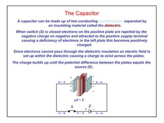
  • 1. The Capacitor A capacitor can be made up of two conducting parallel plates separated by an insulating material called the dielectric. When switch (S) is closed electrons on the positive plate are repelled by the negative charge on negative and attracted to the positive supply terminal causing a deficiency of electrons in the left plate this becomes positively charged. Since electrons cannot pass through the dielectric insulation an electric field is set up within the dielectric causing a charge to exist across the plates. The charge builds up until the potential difference between the plates equals the source (E). S E + - + + + + - - - - pd = E
  • 2. If the switch is opened the conduction path between the plates is removed, the surplus electrons remain on the right plate (negative plate) while the left plate remains deficient in electrons (positive plate). The parallel plates store electric charge causing a potential difference to exist between the two plates. The stored charge will remain indefinitely until the capacitor is discharged. The charge will reduce in time due to leakage of electrons through the dielectric. S E + - + + + + - - - - pd = E The Capacitor
  • 3. Construction of a Capacitor ceramic (dielectric ) silver (plates) Non polarised (can be connected either way round) Polarised Electrolytic (must be connected as shown) + - Circuit Symbols
  • 4. Capacitance is the ability of a capacitor to store electric charge and is, a. directly proportional to its plate area. (capacitance increases with plate area) b. inversely proportional to the distance between the plates. (capacitance decreases with dielectric thickness) c. dependent on the dielectric material used to separate the plates. (various materials are used to obtain the required capacity and dielectric strength) Capacitance
  • 5. The Dielectric The dielectric is the material used to separate the plates of a capacitor. The dielectric constant (k or εr ) also called the relative permittivity of a material is the ratio between the permittivity of a material (ε) and the permittivity of free space (ε0 ). Permittivity relates to a material's ability to "permit" an electric field. The dielectric strength of a material is the maximum electric field strenth that it can withstand without breaking down. Material K or εr Strength (kV/mm) Air 1.0 3 Barium-strontium titanate 7500 3 Polystyrene 2.6 16 Paper 2.5 20 Mylar 3.0 24 Glass 6 120 Mica 5 200 k or εr = ε ε0
  • 6. Capacitance of a Capacitor The capacitance (C) of a capacitor is dependent upon the plate area the distance between the plates in metres and its dielectric constant. Knowing these parameters it is possible to determine the capacitance of any parallel plate capacitor. The unit of capacitance is the Farad (F). where k is the dielectric constant ε0 is permittivity of free space (8.85 x 10⁻¹² ) F/m A is the area of each plate in m2 d is the distance between each plates in m. C = kε0 A Farads d
  • 7. Capacitance of a Capacitor Activity 1 Determine the capacitance of a 2 plate capacitor having a plate dimensions of 2m x 10cm using 0.20mm of paper as its dielectric material. If the dielectric material was changed to mica what would you expect to happen to the capacitance. If the plate area was to double what would be the effect on the capacitance. Activity 2 Choose a suitable dielectric material and determine the plate area for a 25uF 2 plate capacitor having a 0.1mm thickness of dielectric material, for the smallest case size of capacitor. Also state the working voltage, assume 100% margin for safety.
  • 8. Capacitance and Charge A capacitor is a component that stores electric charge. The symbol for capacitance is “C”. The unit of capacitance is the Farad “F”. The unit for charge is the coulomb, “C”. The symbol for charge is “Q”. also Charge, Q = C x V coulombs where C is in Farads coulombs where t is in secondsCharge, Q = I x t
  • 9. Capacitors in Parallel Capacitors connected in parallel effectively increases the plate area and therefore increases the capacitance. The total capacitance of capacitors connected in parallel is the sum of all the individual capacitors. CT = C1 + C2 The total charge drawn from a supply is the sum of the charge stored in each capacitor. QT = QC1 + QC2 =E + - C1 C2 E + - CT
  • 10. Capacitors in Parallel Activity 1. Three capacitors 10uF, 25uF and 50uF are connected in parallel to a 18 volt dc supply. Determine a) the total capacitance, b) the charge on each capacitor and c) the charge drawn from the supply. 2. An electronic circuit operating from a 12 volt dc supply requires a charge of 200uC. If we already have a 12uF capacitor, determine the capacitance that we must connect in parallel with this to obtain the required charge. It is a good idea to sketch these circuits before starting to calculate your results.
  • 11. Capacitors in Series The positive charge on the top plate of C1 attracts electrons from the top plate of C2 to the bottom plate of C1. The negative charge on the bottom plate of C2 repels electrons from the top plate of C2. This effect is the same as increasing the space between the plates thus reducing the capacitance. The total capacitance of capacitors connected in series Since the current is the same in all parts of the series circuit, charge drawn from a supply and the charge on each capacitor is the same. However the pd across individual capacitors will vary. QT = QC1 = QC2 = CT E 1 1 1 CT C1 + C2 = E + - + C2 - + C1 - VC1 = QT C1 VC2 = QT C2
  • 12. Capacitors in Series Activity 1. A 20uF capacitor and 40uF capacitor are connected in series to an 36 volt dc supply. Determine a) the total capacitance, b) the charge on each capacitor, c) the charge drawn from the supply and d) the potential difference developed across each capacitor. 2. Three capacitors 10uF, 25uF and 50uF are connected in series to an 18 volt dc supply. Determine a) the total capacitance, b) the charge on each capacitor and c) the charge drawn from the supply. It is a good idea to sketch these circuits before starting to calculate your results.
  • 13. Capacitors in Combinational Networks Capacitors connected in combinational networks are treated using the principles developed for the series and parallel circuits. CT = C1 + CP QT = CT x E VC1 = VCP =C1 CP QT QT VCP E + - C1 C2 C3 VC1
  • 14. Combinational Networks Activity 1. A 20uF capacitor and 40uF capacitor are connected in parallel and a 30uF is connected in series with this parallel section. If this network is connected to a 36 volt dc supply determine; a) the total capacitance, b) the total charge, c) the potential difference developed across each capacitor. It is a good idea to sketch these circuits before starting to calculate your results.
  • 15. Energy Stored By A Capacitor When a capacitor is charging energy is transferred from the source voltage to the capacitor. When the capacitor is removed from the source the potential difference across its plates remains constant. Since no current is required to maintain this potential difference, the capacitance stores electric energy. This energy is stored in the electric field between the plates. The energy stored by a fully charged capacitor, The letter symbol for energy is “W” The unit for energy is the joule, “J” 1 W = 2 CV2
  • 16. Activity 1. A 470pf high voltage filter capacitor is charged to 12kV, determine the energy stored. 2. A power supply uses two 4700uF capacitors connected in parallel to provide smoothing in a full-wave rectified dc supply. Both capacitors are charged to a peak voltage of 24 volts. Determine a) the energy stored by the combination and b) the current required to charge the capacitors during the 10mS charge time. It is a good idea to sketch these circuits before starting to calculate your results. Energy Stored By A Capacitor