SlideShare ist ein Scribd-Unternehmen logo
1 von 11
The Transformer - The Transformer Principle
When an alternating current is passed through a coil the magnetic
field produced will also alternate.
If a second coil is placed within this magnetic field the alternating flux will link
the two coils and induce an emf in the second coil. This process is called mutual
induction and is also known as the transformer effect.
AC Supply
Alternating
magnetic flux
AC Supply
Alternating
Induced
emf
Primary coil Secondary coil
The Double Wound Transformer
A transformer is commonly used to change (transform) an
alternating voltage from one value to another.
The basic transformer consists of two coils, called the ‘primary’ and
‘secondary’ each electrically ‘isolated’ from the other, there is no
electrical connection between the primary and secondary coils.
Primary
winding
Secondary
winding
Alternating
induced emf
Applied AC
supply
Laminated
iron core
Magnetic
flux
If both coils are mounted on an iron core the magnetic flux and coupling
between coils will increase, this assembly is called a transformer.
The Transformer – Turns Ratio
An alternating current flowing in one winding will produce an alternating flux in the core
and since the turns of both windings cut this flux the emf induced in each turn is the
same for each winding.
The volts per turn for primary and secondary windings are the same.
The ratio of secondary turns (NS) to primary turns (NP) is called the turns ratio.
The ratio of secondary voltage (VS) to primary voltage (VP) depends on the turns ratio.
VP
VSNP
NS
IP
IS
Primary
Winding Secondary
Winding
VP
VS
NP
NS
==
IS
IP
=
The Double Wound Transformer
Activity – Turns Ratio
1. A transformer is required to provide a 60V output from a 240V ac supply.
Calculate (a) the turns ratio required and (b) the number of primary turns, if the
secondary is wound with 500 turns.
2. A transformer operating from a 240V ac supply is required to provide two
secondary windings one of 12 volts and the other 18 volts. If the primary
winding has 2400 turns determine the turns on each secondary winding.
3. A transformer operates from a 240 volt supply and has a secondary voltage
of 24 volts, if this secondary winding has 96 turns determine the turns required
for the primary winding.
The Transformer – Power Conservation
If we neglect transformer losses since they are very small the efficiency can
be taken as 100%, making the secondary power (PS) equal to the primary
power (PP) .
VS
VP
NS
NP
==
PS = PP
VS IS = VP IP
but
IP
IS
=
VS
VP
IP
IS
=
NS
NP
This provides a more general expression linking voltage and turns to the
current in each winding.
VP
VS
NP
NS
==
IS
IP
=
Transformer Rating
When designing or specifying a transformer two main items of information are
needed – Secondary Voltage (V) and Secondary Current (I).
The rating of a transformer is defined in terms of the above information in the
form ‘VA’ (volt-amp).
The ‘VA’ rating is the maximum operating power level a transformer can
deliver to a load.
The above example assumes an ‘ideal’ transformer with no losses.
120VA
Transformer
IP 0.5A IS 6.6A
VP
240V
VS
18V
The Double Wound Transformer
Activity – Transformer Rating
1. A 600VA transformer operating from a 240 volt supply has a 6 volt
secondary winding. Determine the ‘full load’ current capability of the
secondary winding and the current drawn from the supply when operating
at full load.
2. A welding set transformer operating from a 240V mains supply has a
rating of 2000 VA (2kVA). If the full load secondary voltage is 3 volts
determine the a) the maximum welding current and b) the current drawn
from the mains supply under full load.
3. A 60VA transformer has two 12 volt secondary windings, determine the
secondary current capability.
NOTE: In all cases an ideal transformer is assumed.
The Transformer - Losses
Iron (core) loss
Iron losses are made up of ‘hysteresis’ loss and ‘eddy’ current loss
both cause heat to be generated. The iron loss is constant and not
dependant on load conditions meaning that the no-load iron loss is
the same as the full-load iron loss.
Copper (I2
R) loss
Copper losses are due to the effect of resistance on the currents of
primary and secondary windings causing heat to be generated. The
copper loss is a power loss and dependant on the square of the load
current. Therefore a transformer operating at half load will have only
a quarter of the copper loss it has on full-load.
The Transformer – Efficiency
The input power to a transformer provides both the output power and
the transformer losses.
input power = output power + power
losses
efficiency =
output power
input power
x 100%
=
output power
input power + power loses
x 100%efficiency
Primary
winding
Secondary
winding
Output power
PO
Input power
PI
The Transformer – Regulation
The resistance and inductance of a transformer provide an
impedance to the output current resulting in a volt drop due to the
load.
On no-load there will be no secondary current and no volt drop. On
full-load the output voltage will fall.
The difference between the no-load voltage and the full-load voltage,
expressed as a percentage of the no-load voltage is called the
‘voltage regulation’.
no load output voltage – full load output voltage
no load output voltage
x 100%Regulation =
Toroidal Equipment
Transformer
Common Types of Transformer for 50Hz Operation
Package styles vary but all have a laminated iron core to support the magnetic
flux linking the windings.
Chassis Mounted
Equipment
Transformer
Audio
Transformer
Circuit Board Mounted
Equipment Transformer

Weitere ähnliche Inhalte

Was ist angesagt?

Was ist angesagt? (20)

Current Transformer.pptx
Current Transformer.pptxCurrent Transformer.pptx
Current Transformer.pptx
 
Current Transformer
Current TransformerCurrent Transformer
Current Transformer
 
Introduction to CTs and PTs
Introduction to CTs and PTsIntroduction to CTs and PTs
Introduction to CTs and PTs
 
Parallel Operation of a Single Phase Transformer
Parallel Operation of a Single Phase TransformerParallel Operation of a Single Phase Transformer
Parallel Operation of a Single Phase Transformer
 
ELECTRICAL MEASUREMENT & MEASURING INSTRUMENTS [Emmi- (NEE-302) -unit-1]
ELECTRICAL MEASUREMENT & MEASURING INSTRUMENTS [Emmi- (NEE-302) -unit-1]ELECTRICAL MEASUREMENT & MEASURING INSTRUMENTS [Emmi- (NEE-302) -unit-1]
ELECTRICAL MEASUREMENT & MEASURING INSTRUMENTS [Emmi- (NEE-302) -unit-1]
 
Open circuit and Short circuit test on transformer
Open circuit and Short circuit test on transformerOpen circuit and Short circuit test on transformer
Open circuit and Short circuit test on transformer
 
Introduction to CTs and PTs
Introduction to CTs and PTsIntroduction to CTs and PTs
Introduction to CTs and PTs
 
Armature windings
Armature windingsArmature windings
Armature windings
 
TRANSFORMER PPT
TRANSFORMER PPT TRANSFORMER PPT
TRANSFORMER PPT
 
Transformer
Transformer Transformer
Transformer
 
Presentation on Distribution Transformer by nirob dhilon chowdhury
Presentation on Distribution Transformer by nirob dhilon chowdhuryPresentation on Distribution Transformer by nirob dhilon chowdhury
Presentation on Distribution Transformer by nirob dhilon chowdhury
 
Single phase transformer
Single phase transformerSingle phase transformer
Single phase transformer
 
Unit-2 Three Phase controlled converter
Unit-2 Three Phase controlled converter Unit-2 Three Phase controlled converter
Unit-2 Three Phase controlled converter
 
Transformer basic
Transformer basicTransformer basic
Transformer basic
 
Transformer
TransformerTransformer
Transformer
 
Efficiency of a transformer
Efficiency of a transformerEfficiency of a transformer
Efficiency of a transformer
 
Autotransformer
AutotransformerAutotransformer
Autotransformer
 
Testing of dc machines_I
Testing of dc machines_ITesting of dc machines_I
Testing of dc machines_I
 
Inverter
InverterInverter
Inverter
 
Transformer : Equivalent Circuit
Transformer : Equivalent CircuitTransformer : Equivalent Circuit
Transformer : Equivalent Circuit
 

Andere mochten auch

The transformer
The transformerThe transformer
The transformer
Srajan Raj
 
Elect principles -_kirchhoffs_laws
Elect principles -_kirchhoffs_lawsElect principles -_kirchhoffs_laws
Elect principles -_kirchhoffs_laws
sdacey
 
Transformer testing
Transformer testingTransformer testing
Transformer testing
ajayknows
 

Andere mochten auch (20)

PRESENTATION ON MANUFACTURING OF TRANSFORMER By Dhruv Jimit
PRESENTATION ON MANUFACTURING OF TRANSFORMER By Dhruv JimitPRESENTATION ON MANUFACTURING OF TRANSFORMER By Dhruv Jimit
PRESENTATION ON MANUFACTURING OF TRANSFORMER By Dhruv Jimit
 
Transformer construction,types and working
Transformer construction,types and workingTransformer construction,types and working
Transformer construction,types and working
 
Power Transformer Parts And Functions
Power Transformer Parts And FunctionsPower Transformer Parts And Functions
Power Transformer Parts And Functions
 
Transformer
TransformerTransformer
Transformer
 
Transformer a short presentation
Transformer a short presentationTransformer a short presentation
Transformer a short presentation
 
Transformers
TransformersTransformers
Transformers
 
The transformer
The transformerThe transformer
The transformer
 
Elect principles -_kirchhoffs_laws
Elect principles -_kirchhoffs_lawsElect principles -_kirchhoffs_laws
Elect principles -_kirchhoffs_laws
 
ABCB(air blast circuit breaker)
ABCB(air blast circuit breaker)ABCB(air blast circuit breaker)
ABCB(air blast circuit breaker)
 
Power transformer
Power transformerPower transformer
Power transformer
 
Basic Protection of transformer using microcontroller based relay
Basic Protection of transformer using microcontroller based relayBasic Protection of transformer using microcontroller based relay
Basic Protection of transformer using microcontroller based relay
 
Hysteresis loop
Hysteresis loopHysteresis loop
Hysteresis loop
 
the substation components study
the substation components study the substation components study
the substation components study
 
Hysteresis and Eddy-current losses
Hysteresis and Eddy-current lossesHysteresis and Eddy-current losses
Hysteresis and Eddy-current losses
 
Simplifying Ratios
Simplifying RatiosSimplifying Ratios
Simplifying Ratios
 
Sensors And Actuators
Sensors And ActuatorsSensors And Actuators
Sensors And Actuators
 
Training from 220kv GSS Sanganer, which is located on Muhana Road, Jaipur
Training from 220kv GSS Sanganer, which is located on Muhana Road, JaipurTraining from 220kv GSS Sanganer, which is located on Muhana Road, Jaipur
Training from 220kv GSS Sanganer, which is located on Muhana Road, Jaipur
 
Microsoft Excel
 Microsoft Excel Microsoft Excel
Microsoft Excel
 
A 220kV Substation
A 220kV SubstationA 220kV Substation
A 220kV Substation
 
Transformer testing
Transformer testingTransformer testing
Transformer testing
 

Ähnlich wie Components the transformer

9.3 transformers
9.3 transformers9.3 transformers
9.3 transformers
pixelcowboy
 
Transformer
TransformerTransformer
Transformer
stooty s
 

Ähnlich wie Components the transformer (20)

Full transformer
Full transformerFull transformer
Full transformer
 
Transformers basic electrical engineering
Transformers basic electrical engineeringTransformers basic electrical engineering
Transformers basic electrical engineering
 
2016 Chapter -2 (transformer).pptx
2016            Chapter -2 (transformer).pptx2016            Chapter -2 (transformer).pptx
2016 Chapter -2 (transformer).pptx
 
Transformer.pptx
Transformer.pptxTransformer.pptx
Transformer.pptx
 
Presentation on Transformer,it's working principle
Presentation on Transformer,it's working principlePresentation on Transformer,it's working principle
Presentation on Transformer,it's working principle
 
Transformer
TransformerTransformer
Transformer
 
Chapter two
Chapter twoChapter two
Chapter two
 
Single and three phase Transformers
Single and three phase TransformersSingle and three phase Transformers
Single and three phase Transformers
 
Transformer
TransformerTransformer
Transformer
 
9.3 transformers
9.3 transformers9.3 transformers
9.3 transformers
 
Transformers
TransformersTransformers
Transformers
 
Engineering science lesson 10
Engineering science lesson 10Engineering science lesson 10
Engineering science lesson 10
 
Engineering science lesson 10 1
Engineering science lesson 10 1Engineering science lesson 10 1
Engineering science lesson 10 1
 
Transformer part-1
Transformer part-1Transformer part-1
Transformer part-1
 
Unit 2 - Transformers.pdf
Unit 2 - Transformers.pdfUnit 2 - Transformers.pdf
Unit 2 - Transformers.pdf
 
Chapter 2 mukesh gurjar
Chapter 2 mukesh gurjarChapter 2 mukesh gurjar
Chapter 2 mukesh gurjar
 
Shazab
ShazabShazab
Shazab
 
Chapter 2
Chapter 2Chapter 2
Chapter 2
 
4_5857160069648490643.ppt
4_5857160069648490643.ppt4_5857160069648490643.ppt
4_5857160069648490643.ppt
 
Transformer
TransformerTransformer
Transformer
 

Mehr von sdacey

Elect principles 2 three phase systems
Elect principles 2   three phase systemsElect principles 2   three phase systems
Elect principles 2 three phase systems
sdacey
 
Elect principles 2 ac circuits parallel
Elect principles 2   ac circuits parallelElect principles 2   ac circuits parallel
Elect principles 2 ac circuits parallel
sdacey
 
Elect principles 2 ac circuits series resonance
Elect principles 2   ac circuits series resonanceElect principles 2   ac circuits series resonance
Elect principles 2 ac circuits series resonance
sdacey
 
Elect principles 2 ac circuits (rl)
Elect principles 2   ac circuits (rl)Elect principles 2   ac circuits (rl)
Elect principles 2 ac circuits (rl)
sdacey
 
Elect principles 2 filter networks
Elect principles 2   filter networksElect principles 2   filter networks
Elect principles 2 filter networks
sdacey
 
Elect principles 2 three phase systems
Elect principles 2   three phase systemsElect principles 2   three phase systems
Elect principles 2 three phase systems
sdacey
 
Elect principles 2 power in ac circuits
Elect principles 2   power in ac circuitsElect principles 2   power in ac circuits
Elect principles 2 power in ac circuits
sdacey
 
Elect principles 2 filter networks
Elect principles 2   filter networksElect principles 2   filter networks
Elect principles 2 filter networks
sdacey
 
Elect principles 2 current divider
Elect principles 2   current dividerElect principles 2   current divider
Elect principles 2 current divider
sdacey
 
Elect principles 2 power factor
Elect principles 2   power factorElect principles 2   power factor
Elect principles 2 power factor
sdacey
 
Elect principles 2 voltage divider
Elect principles 2   voltage dividerElect principles 2   voltage divider
Elect principles 2 voltage divider
sdacey
 
Elect principles 2 max power transfer
Elect principles 2   max power transferElect principles 2   max power transfer
Elect principles 2 max power transfer
sdacey
 
Elect principles 2 dc transients (inductive)
Elect principles 2   dc transients (inductive)Elect principles 2   dc transients (inductive)
Elect principles 2 dc transients (inductive)
sdacey
 
Elect principles 2 dc transients (capacitive)
Elect principles 2   dc transients (capacitive)Elect principles 2   dc transients (capacitive)
Elect principles 2 dc transients (capacitive)
sdacey
 
Elect principles 2 nortons theorem
Elect principles 2   nortons theoremElect principles 2   nortons theorem
Elect principles 2 nortons theorem
sdacey
 
Elect principles 2 thevenin theorem
Elect principles 2   thevenin theoremElect principles 2   thevenin theorem
Elect principles 2 thevenin theorem
sdacey
 
Electronics power supplies
Electronics   power suppliesElectronics   power supplies
Electronics power supplies
sdacey
 
Machines the dc motor
Machines   the dc motorMachines   the dc motor
Machines the dc motor
sdacey
 
Elect principles -_resistance
Elect principles -_resistanceElect principles -_resistance
Elect principles -_resistance
sdacey
 
Elect principles -_ac_circuits_year1
Elect principles -_ac_circuits_year1Elect principles -_ac_circuits_year1
Elect principles -_ac_circuits_year1
sdacey
 

Mehr von sdacey (20)

Elect principles 2 three phase systems
Elect principles 2   three phase systemsElect principles 2   three phase systems
Elect principles 2 three phase systems
 
Elect principles 2 ac circuits parallel
Elect principles 2   ac circuits parallelElect principles 2   ac circuits parallel
Elect principles 2 ac circuits parallel
 
Elect principles 2 ac circuits series resonance
Elect principles 2   ac circuits series resonanceElect principles 2   ac circuits series resonance
Elect principles 2 ac circuits series resonance
 
Elect principles 2 ac circuits (rl)
Elect principles 2   ac circuits (rl)Elect principles 2   ac circuits (rl)
Elect principles 2 ac circuits (rl)
 
Elect principles 2 filter networks
Elect principles 2   filter networksElect principles 2   filter networks
Elect principles 2 filter networks
 
Elect principles 2 three phase systems
Elect principles 2   three phase systemsElect principles 2   three phase systems
Elect principles 2 three phase systems
 
Elect principles 2 power in ac circuits
Elect principles 2   power in ac circuitsElect principles 2   power in ac circuits
Elect principles 2 power in ac circuits
 
Elect principles 2 filter networks
Elect principles 2   filter networksElect principles 2   filter networks
Elect principles 2 filter networks
 
Elect principles 2 current divider
Elect principles 2   current dividerElect principles 2   current divider
Elect principles 2 current divider
 
Elect principles 2 power factor
Elect principles 2   power factorElect principles 2   power factor
Elect principles 2 power factor
 
Elect principles 2 voltage divider
Elect principles 2   voltage dividerElect principles 2   voltage divider
Elect principles 2 voltage divider
 
Elect principles 2 max power transfer
Elect principles 2   max power transferElect principles 2   max power transfer
Elect principles 2 max power transfer
 
Elect principles 2 dc transients (inductive)
Elect principles 2   dc transients (inductive)Elect principles 2   dc transients (inductive)
Elect principles 2 dc transients (inductive)
 
Elect principles 2 dc transients (capacitive)
Elect principles 2   dc transients (capacitive)Elect principles 2   dc transients (capacitive)
Elect principles 2 dc transients (capacitive)
 
Elect principles 2 nortons theorem
Elect principles 2   nortons theoremElect principles 2   nortons theorem
Elect principles 2 nortons theorem
 
Elect principles 2 thevenin theorem
Elect principles 2   thevenin theoremElect principles 2   thevenin theorem
Elect principles 2 thevenin theorem
 
Electronics power supplies
Electronics   power suppliesElectronics   power supplies
Electronics power supplies
 
Machines the dc motor
Machines   the dc motorMachines   the dc motor
Machines the dc motor
 
Elect principles -_resistance
Elect principles -_resistanceElect principles -_resistance
Elect principles -_resistance
 
Elect principles -_ac_circuits_year1
Elect principles -_ac_circuits_year1Elect principles -_ac_circuits_year1
Elect principles -_ac_circuits_year1
 

Components the transformer

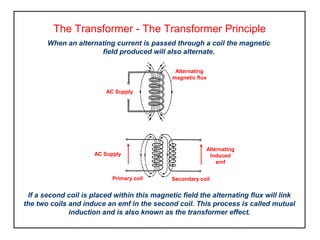
  • 1. The Transformer - The Transformer Principle When an alternating current is passed through a coil the magnetic field produced will also alternate. If a second coil is placed within this magnetic field the alternating flux will link the two coils and induce an emf in the second coil. This process is called mutual induction and is also known as the transformer effect. AC Supply Alternating magnetic flux AC Supply Alternating Induced emf Primary coil Secondary coil
  • 2. The Double Wound Transformer A transformer is commonly used to change (transform) an alternating voltage from one value to another. The basic transformer consists of two coils, called the ‘primary’ and ‘secondary’ each electrically ‘isolated’ from the other, there is no electrical connection between the primary and secondary coils. Primary winding Secondary winding Alternating induced emf Applied AC supply Laminated iron core Magnetic flux If both coils are mounted on an iron core the magnetic flux and coupling between coils will increase, this assembly is called a transformer.
  • 3. The Transformer – Turns Ratio An alternating current flowing in one winding will produce an alternating flux in the core and since the turns of both windings cut this flux the emf induced in each turn is the same for each winding. The volts per turn for primary and secondary windings are the same. The ratio of secondary turns (NS) to primary turns (NP) is called the turns ratio. The ratio of secondary voltage (VS) to primary voltage (VP) depends on the turns ratio. VP VSNP NS IP IS Primary Winding Secondary Winding VP VS NP NS == IS IP =
  • 4. The Double Wound Transformer Activity – Turns Ratio 1. A transformer is required to provide a 60V output from a 240V ac supply. Calculate (a) the turns ratio required and (b) the number of primary turns, if the secondary is wound with 500 turns. 2. A transformer operating from a 240V ac supply is required to provide two secondary windings one of 12 volts and the other 18 volts. If the primary winding has 2400 turns determine the turns on each secondary winding. 3. A transformer operates from a 240 volt supply and has a secondary voltage of 24 volts, if this secondary winding has 96 turns determine the turns required for the primary winding.
  • 5. The Transformer – Power Conservation If we neglect transformer losses since they are very small the efficiency can be taken as 100%, making the secondary power (PS) equal to the primary power (PP) . VS VP NS NP == PS = PP VS IS = VP IP but IP IS = VS VP IP IS = NS NP This provides a more general expression linking voltage and turns to the current in each winding. VP VS NP NS == IS IP =
  • 6. Transformer Rating When designing or specifying a transformer two main items of information are needed – Secondary Voltage (V) and Secondary Current (I). The rating of a transformer is defined in terms of the above information in the form ‘VA’ (volt-amp). The ‘VA’ rating is the maximum operating power level a transformer can deliver to a load. The above example assumes an ‘ideal’ transformer with no losses. 120VA Transformer IP 0.5A IS 6.6A VP 240V VS 18V
  • 7. The Double Wound Transformer Activity – Transformer Rating 1. A 600VA transformer operating from a 240 volt supply has a 6 volt secondary winding. Determine the ‘full load’ current capability of the secondary winding and the current drawn from the supply when operating at full load. 2. A welding set transformer operating from a 240V mains supply has a rating of 2000 VA (2kVA). If the full load secondary voltage is 3 volts determine the a) the maximum welding current and b) the current drawn from the mains supply under full load. 3. A 60VA transformer has two 12 volt secondary windings, determine the secondary current capability. NOTE: In all cases an ideal transformer is assumed.
  • 8. The Transformer - Losses Iron (core) loss Iron losses are made up of ‘hysteresis’ loss and ‘eddy’ current loss both cause heat to be generated. The iron loss is constant and not dependant on load conditions meaning that the no-load iron loss is the same as the full-load iron loss. Copper (I2 R) loss Copper losses are due to the effect of resistance on the currents of primary and secondary windings causing heat to be generated. The copper loss is a power loss and dependant on the square of the load current. Therefore a transformer operating at half load will have only a quarter of the copper loss it has on full-load.
  • 9. The Transformer – Efficiency The input power to a transformer provides both the output power and the transformer losses. input power = output power + power losses efficiency = output power input power x 100% = output power input power + power loses x 100%efficiency Primary winding Secondary winding Output power PO Input power PI
  • 10. The Transformer – Regulation The resistance and inductance of a transformer provide an impedance to the output current resulting in a volt drop due to the load. On no-load there will be no secondary current and no volt drop. On full-load the output voltage will fall. The difference between the no-load voltage and the full-load voltage, expressed as a percentage of the no-load voltage is called the ‘voltage regulation’. no load output voltage – full load output voltage no load output voltage x 100%Regulation =
  • 11. Toroidal Equipment Transformer Common Types of Transformer for 50Hz Operation Package styles vary but all have a laminated iron core to support the magnetic flux linking the windings. Chassis Mounted Equipment Transformer Audio Transformer Circuit Board Mounted Equipment Transformer