
Empfohlen
Weitere ähnliche Inhalte
Was ist angesagt?
Was ist angesagt? (20)
Andere mochten auch
Ähnlich wie Seepage analysis final
Ähnlich wie Seepage analysis final (20)
Kürzlich hochgeladen
Kürzlich hochgeladen (20)
Seepage analysis final
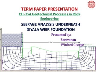
- 1. Presented by: Saravanan Winfred George
- 2. Introduction The construction of Diyala weir commenced in 1966 and was completed in 1969. The structure includes a road bridge and new canal head works. This structure is located 7km downstream from the Hamren dam, approximately 130 Km northeast of Baghdad, near the town of Sidor. The main purpose of this Weir is to divert outflow of the Hamren dam to the Khalis and Sadr Al-Mushtarak canals for irrigation.
- 5. Section of Diyala Weir
- 6. The Problem Seepage of water is one of the major problems, which has an effect upon hydraulic structures. Diyala weir structure is suffering from such engineering problems. It was taken as a case study and it had been checked against piping and uplift pressure by using numerical model. The effect of removing one of the three sheet piles rows was studied and evaluated to investigate the quantity of seepage, uplift pressure and expected exit hydraulic gradient for these cases.
- 7. Input Data for Seepage Analysis Total length of a weir foundation equals 24.5 m. Depth of 1st row of sheet piles (upstream sheet pile) equals 4.5 m. Depth of 2nd row of sheet piles (middle sheet pile) equals 2.5 m. Depth of 3rd row of sheet piles (downstream sheet pile) equals 3.5 m. Unit weight of the soil underneath Diyala weir equals 18 kN/m2. Permeability for clay soil underneath Diyala weir equals 1e-5 m/s. Depth of impervious layer below Diyala weir foundation equals 11m from the bed level (B.L). Soil foundation underneath the weir is saturated, isotropic and homogenous.
- 8. Seepage Analysis by FEA
- 9. Seepage Analysis by FEA (Contd.)
- 10. FEM Model Properties The Eight noded quadrilateral elements were used to idealize the vertical cross section of permeable soil underneath Diyala weir with the following Mesh Properties, Mesh type: graded Analysis Type: Plane Strain Number of elements: 1278 Solver Type: Gaussian Elimination Maximum Number of Iterations: 500 Number of nodes: 3989 Tolerance: 1e-006
- 11. Diyala Weir Model in Phase2 with all Cutoff
- 12. Seepage Results from Phase2 with all cutoff
- 13. 6.00 5.00 4.00 3.00 15.00 16.00 17.00 18.00 19.00 20.00 21.00 22.00 23.00 24.00
- 14. Uplift Pressure (Contd.) The thickness of weir impervious floor at any point should not be less than 2/3 of uplift pressure. The required floor thickness for points below downstream floor and the provided floor thickness are tabulated below,
- 15. Uplift Pressure along Base Slab 0.00 4.00 8.00 12.00 16.00 20.00 24.00 62.00 63.00 64.00 65.00 66.00 67.00 68.00
- 16. Floor Thickness Distance Floor Elevation Total Pressure at Required Floor Provided Floor Uplift Pressure (m) Calculated by Diff along D/s (m) (m) Base (m) Thickness (m) Thickness (m) Authors 0.00 61.50 68.00 6.50 4.33 - 6.00 1.67 1.00 60.50 66.05 5.55 3.70 - 5.92 2.22 2.00 60.50 66.03 5.53 3.69 - 5.58 1.90 3.00 60.50 66.01 5.51 3.67 - 5.24 1.57 4.00 61.50 65.51 4.01 2.67 - 3.91 1.24 5.00 61.50 65.50 4.00 2.66 - 3.58 0.91 6.00 61.33 65.47 4.14 2.76 - 3.41 0.65 7.00 61.00 65.43 4.43 2.95 - 3.41 0.45 8.00 60.67 65.36 4.69 3.13 - 3.40 0.28 9.00 60.33 65.27 4.94 3.29 - 3.40 0.11 10.00 60.00 65.17 5.17 3.45 - 3.40 -0.05 11.00 59.67 65.05 5.39 3.59 - 3.40 -0.19 12.00 59.33 64.92 5.59 3.73 - 3.40 -0.33 13.00 59.00 64.76 5.76 3.84 - 3.40 -0.45 14.00 59.00 64.61 5.61 3.74 - 3.06 -0.68 15.00 59.00 64.46 5.46 3.64 2.49 2.73 -0.92 16.00 59.00 64.33 5.33 3.55 2.41 2.50 -1.05 17.00 59.00 64.19 5.19 3.46 2.34 2.50 -0.96 18.00 59.00 64.06 5.06 3.37 2.26 2.50 -0.87 19.00 59.00 63.91 4.91 3.27 2.22 2.50 -0.77 20.00 59.50 63.81 4.31 2.87 1.93 2.00 -0.87 21.00 59.50 63.73 4.23 2.82 1.89 2.00 -0.82 22.00 59.50 63.66 4.16 2.77 1.85 2.00 -0.77 23.00 59.50 63.61 4.11 2.74 1.83 2.00 -0.74 24.00 59.50 62.05 2.55 1.70 1.00 2.00 0.30
- 17. Exit Gradient (Contd.) The critical hydraulic gradient (icr ) was calculated from, The unit weight of saturated soil underneath the weir structure is 18 kN/m2 and unit weight of water 9.807 kN/m2. The calculated value of the critical hydraulic gradient is 0.835. This lead to factor of Safety against piping equals; The exit gradient from the Analysis is 0.17, lead to Fs = 4.9. A factor of safety (Fs) of 4.9 is considered adequate for the safe performance of the Diyala weir structure against piping
- 18. Exit Gradient Plot from Phase2 with all cutoff The Exit Gradient Value from SEEP / W is 0.17 The Exit Gradient from Phase 2 is 0.18
- 19. Pressure Plot with No U/S cutoff
- 20. Exit Gradient Plot with No U/S cutoff The Exit Gradient Value from SEEP / W is 0.19 The Exit Gradient from Phase 2 is 0.24
- 21. Pressure Plot with No U/S cutoff
- 22. Pressure Plot with No Middle cutoff
- 23. Exit Gradient Plot with No Middle cutoff The Exit Gradient Value from SEEP / W is 0.17 The Exit Gradient from Phase 2 is 0.20
- 24. Pressure Plot with No End cutoff
- 25. Exit Gradient Plot with No End cutoff The Exit Gradient Value from SEEP / W is 0.21 The Exit Gradient from Phase 2 is 0.25
- 26. Seepage and Exit Gradient The below results of quantity of seepage and exit gradient for each case as one sheet pile assumed to be removed. Without Ist Sheet Pile Without IInd Sheet Pile Without IIIrd Sheet Pile Description Author's Ours Author's Ours Author's Ours Quantity of Seepage 1.10E-05 1.33E-05 9.62E-06 1.19E-05 1.05E-05 1.31E-05 (m3/s) Exit Gradient 0.19 0.24 0.17 0.2 0.21 0.25 Factor of Safety 4.4 3.5 4.9 4.2 3.9 3.34 It is noted from the results of removing the first sheet pile is more effective on increasing of seepage while removing the third sheet pile is more effective on increasing of exit gradient values but the factor of safety against piping (Fs) for all values represent safe situation.
- 27. Summary of Results The following results are obtained by using 2-D finite element model of Diyala Weir, Foundation of Diyala weir is safe against piping and any excessive uplift pressures. The defect in one or more of the three sheet piles has caused displacement of the downstream floor (apron slab), cracking in weir foundation and scour of soil underneath the weir, due to increasing the quantity of seepage, uplift pressure and exit gradient.
- 28. Summary of Results (Contd.) Investigation of failure leads to suspect that the sheet piles in upstream is exposing, and could be corroded and defected. The defects in the first row of sheet piles are more effective on increasing uplift pressure and quantity of seepage than the other two rows of sheet piles while defects in the last rows of sheet piles are the most effective on increasing the exit hydraulic gradient.
- 29. Conclusion This research suggests solutions for preventing expected weir foundation failure problems by: Improving the seal between elements of the sheet piles and repairing any defects. Sealing any cracks in the weir foundation by injection of chemical materials or cement grout. The Same Problem also validated with another FEM software (Phase2) successfully.
- 31. Diyala Weir Model in SEEP/W
- 32. Seepage Results from SEEP/W