Mattingly "AI & Prompt Design: The Basics of Prompt Design"
Lec.-3 (1).pdf
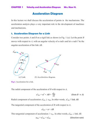
1. CHAPTER 1 Velocity and Acceleration Diagram Mrs. Noor H.
Acceleration Diagram
In this lecture we shall discuss the acceleration of points in the mechanisms. The
acceleration analysis plays a very important role in the development of machines
and mechanisms.
1. Acceleration Diagram for a Link
Consider two points A and B on a rigid link as shown in Fig. 1 (a). Let the point B
moves with respect to A, with an angular velocity of ω rad/s and let α rad/s2
be the
angular acceleration of the link AB.
Fig.1. Acceleration for a link.
The radial component of the acceleration of B with respect to A,
ar
BA = 2
× AB = (from B A)
Radial component of acceleration ar
BA vBA, In other words, ar
BA // link AB.
The tangential component of the acceleration of B with respect to A,
at
BA = × AB
This tangential component of acceleration // vBA. In other words, at
BA link AB.
aBA = ar
BA + at
BA (direction sum)
2. CHAPTER 1 Velocity and Acceleration Diagram Mrs. Noor H.
i. e. aBA = √
2. Acceleration of a Point on a Link
Consider two points A and B on the rigid link, as shown in Fig. 2 (a). Let the
acceleration of the point A i.e. aA is known in magnitude and direction and the
direction of path of B is given. The acceleration of the point B is determined in
magnitude and direction by drawing the acceleration diagram as discussed below.
Fig. 2. Acceleration of a point on a link.
1. From any point o', draw vector o'a' parallel to the direction of absolute
acceleration at point A i.e. aA , to some suitable scale, as shown in Fig. 2 (b).
2. The acceleration of B with respect to A i.e. aBA has two components ar
BA and
at
BA. These two components are mutually perpendicular.
3. Draw vector a'x // link AB, vector a'x = ar
BA =
4. From point x, draw vector xb' link AB or vector a'x (because at
BA ar
BA) and
through o' draw a line parallel to the path of B to represent the absolute
acceleration of B i.e. aB. The vectors xb' and o'b' intersect at b'. Now the values
of aB and at
BA may be measured, to the scale.
3. CHAPTER 1 Velocity and Acceleration Diagram Mrs. Noor H.
5. By joining the points a' and b' we may determine the total acceleration of B
with respect to A i.e. aBA. The vector a' b' is known as acceleration image of
the link AB.
6. For any other point C on the link, draw triangle a' b' c' similar to triangle ABC.
vector ́ ́ = aCB, and vector a'c' = aCA.
aCB and aCA will each have two components as follows :
i. aCB has two components; ar
CB and at
CB as shown by triangle b'zc' in Fig. 2 (b),
in which b'z // BC and zc' b'z or BC.
ii. aCA has two components; ar
CA and at
CA as shown by triangle a'yc' in Fig. 2 (b),
in which a'y // AC and yc' a' y or AC.
7. Angular acceleration of the link AB,
AB =
3. Acceleration in the Slider Crank Mechanism
A slider crank mechanism is shown in Fig. 3 (a). Let the crank OB makes an angle
with horizontal and rotates in a clockwise direction about the fixed point O with
uniform angular velocity BO rad/s.
vBO = vB = BO × OB
Radial acceleration of B (because O is a fixed point),
ar
BO = aB = 2
BO × OB =
Note: A point at the end of a link which moves with constant angular velocity has
no tangential component of acceleration, at
BO = 0.
The acceleration diagram, as shown in Fig. 3(b), may now be drawn as
discussed below:
1. Draw vector o' b' // BO represent ar
BO = aB, to some suitable scale.
2. From point b', draw vector b'x // BA,
vector b'x = ar
BA =
4. CHAPTER 1 Velocity and Acceleration Diagram Mrs. Noor H.
Fig. 3. Acceleration in the slider crank mechanism.
3. From point x, draw vector xa' b'x (or AB). The vector xa' represents at
AB .
4. From o', draw o'a' // AO, intersecting the vector xa' at a'.
Now the acceleration of the piston or the slider A (aA) and at
AB may be measured to
the scale.
5. aAB = vector b'a' = b' x + x a' (vectors sum)
6. The acceleration of any other point on AB such as E can be obtained by
=
7. Angular acceleration of the connecting rod AB,
AB = (Clockwise about B)
Example: 1
The crank of a slider crank mechanism rotates clockwise at a constant speed of
300 r.p.m. The crank is 150 mm and the connecting rod is 600 mm long.
Determine :
1. linear velocity and acceleration of the midpoint of the connecting rod, and
2. angular velocity and angular acceleration of the connecting rod, at a crank
angle of 45° from inner dead centre position.
Solution:
1. Draw the mechanism, to some suitable scale, as shown in Fig.(a).
let 100 mm = 1 cm in paper
2. Find vBO = vB = BO × OB
NOB = 300 r.p.m. , BA = 2 × 300/60 = 31.42 rad/s
vBO = vB = 31.42 × 150 = 4.713 m/s
5. CHAPTER 1 Velocity and Acceleration Diagram Mrs. Noor H.
3. Draw the velocity diagram, as shown in Fig. (b), since the point O is fixed.
Now from point o, draw vector ob OB, to some suitable scale.
let 4.713 m/s = 5 cm in paper
vector ob = vB
4. From point b draw vector ba BA to represent vAB, and from point o, draw
vector oa parallel to the motion of A (which is along AO) to represent vA. The
vectors ba and oa intersect at a.
By measurement, we find that
vAB = vector ab = 3.6 × = 3.4 m/s
Angular velocity of the connecting rod = AB = = = 5.67 rad/s.
(Anticlockwise about B) Ans.
vA = vector oa = 4.2 × = 4 m/s
5. Since the point D lies on AB,
=
Note: Point D is the midpoint of AB, therefore d is also midpoint of vector ba.
By measurement, we find that
vD = vector od = 4.3 × = 4.1 m/s Ans.
Draw the acceleration diagram, as shown in Fig. (c)
1. ar
BO = aB = = = 148.1 m/s2
ar
AB = = = 19.3 m/s2
Scale for acceleration diagram: let 148.1 m/s2
= 5 cm in paper
2. Draw vector o'b' // BO to represent ar
BO or aB,
vector o'b' = ar
= a = 5 cm (from B O)
6. CHAPTER 1 Velocity and Acceleration Diagram Mrs. Noor H.
Note: Since the crank OB rotates at a constant speed, therefore at
BO = 0
3. The acceleration of A with respect to B (aAB) has two components:
aAB = ar
AB + at
AB
from point b', draw vector b' x // AB to represent ar
AB = 19.3 m/s = 0.7 cm in paper
(from A B), and from point x draw vector xa' vector b'x whose magnitude is
yet unknown.
4. Now from o', draw vector o'a' parallel to the path of motion of A (which is
along AO) to represent aA . The vectors xa' and o'a' intersect at a'. Join a' b'.
5. Point D is the midpoint of AB, therefore d' is also midpoint of vector b'a',
́ ́
=
́ ́
Vector ́ ́ = 3.95 cm in paper
aD = vector ́ ́ = 3.95 × = 117 m/s2
Ans.
́ ́ = 3.45 cm in paper
at
AB = vector ́ ́ = 3.45 × = 103 m/s2
AB = = = 171.67 m/s2
(Clockwise about B) Ans.
Example :2
In the mechanism, as shown in Figure below, the crank OA rotates at 20 r.p.m.
anticlockwise and gives motion to the sliding blocks B and D. The dimensions of
the various links are OA = 300 mm; AB = 1200 mm; BC = 450 mm and CD = 450
mm. For the given configuration, determine :
1. velocities of sliding at B and D,
2. Angular velocity of CD,
3. linear acceleration of D, and
4. angular acceleration of CD.