
Empfohlen
Empfohlen
Weitere ähnliche Inhalte
Was ist angesagt?
Was ist angesagt? (20)
Ähnlich wie NTPC summer training report
Ähnlich wie NTPC summer training report (20)
Kürzlich hochgeladen
Kürzlich hochgeladen (20)
NTPC summer training report
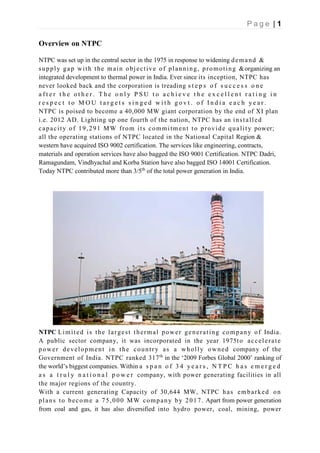
- 1. P a g e | 1 Overview on NTPC NTPC was set up in the central sector in the 1975 in response to widening demand & supply gap with the main objective of planning, promoting &organizing an integrated development to thermal power in India. Ever since its inception, NTPC has never looked back and the corporation is treading s t e p s o f s u c c e s s o n e a f t e r t h e o t h e r . T h e o n l y P S U t o a c h i e v e t h e e x c e l l e n t r a t i n g i n r e s p e c t t o M O U t a r g e t s s i n g e d w i t h g o v t . o f I n d i a e a c h y e a r . NTPC is poised to become a 40,000 MW giant corporation by the end of XI plan i.e. 2012 AD. Lighting up one fourth of the nation, NTPC has an installed capacity of 19,291 MW from its commitment to provide quality power; all the operating stations of NTPC located in the National Capital Region & western have acquired ISO 9002 certification. The services like engineering, contracts, materials and operation services have also bagged the ISO 9001 Certification. NTPC Dadri, Ramagundam, Vindhyachal and Korba Station have also bagged ISO 14001 Certification. Today NTPC contributed more than 3/5th of the total power generation in India. NTPC Limited is the largest thermal power generating company of India. A public sector company, it was incorporated in the year 1975to accelerate power development in the country as a wholly owned company of the Government of India. NTPC ranked 317th in the ‘2009 Forbes Global 2000’ ranking of the world’s biggest companies. Within a s p a n o f 3 4 y e a r s , N T P C h a s e m e r g e d a s a t r u l y n a t i o n a l p o w e r company, with power generating facilities in all the major regions of the country. With a current generating Capacity of 30,644 MW, NTPC has embarked on plans to become a 75,000 MW company by 2017. Apart from power generation from coal and gas, it has also diversified into hydro power, coal, mining, power
- 2. P a g e | 2 equipment, manufacturing, oil and gas exploration, consultancy in the area of the power plant construction and generation, power handling, distribution in the form of joint ventures and various other entities in the India and abroad.
- 3. P a g e | 3 T H E R M AL C O A L B A S E D : S. NO. CITY STATE INSTALLED CAPACITY(MW) 1. SINGRAULI UTTAR PRADESH 2000 2. KORBA CHATTISGHAR 2600 3. RAMAGUNDAM ANDHRA PRADESH 2600 4. FARAKKA WEST BENGAL 2100 5. VINDHYACHAL MADHYA PRADESH 3260 6. RIHAND UTTAR PRADESH 2500 7. KAHALGAON BIHAR 2300 8. DADRI UTTAR PRADESH 1820 9. TALCHER ORISSA 3000 10. UNCHAHAR UTTAR PRADESH 1050 11. TALCHER ORISSA 460 12. SIMHADRI ANDHRA PRADESH 1500 13. TANDA UTTAR PRADESH 440 14. BADARPUR DELHI 705 15. SIPAT CHHATTISGHAR 2320 16. SIPAT CHHATTISGHAR 1980 17. BONGAIGAON ASSAM 750 18. MOUDA MAHARASHTRA 1000(2*500MW) 19. RIHAND UTTAR PRADESH 2*500MW 20. BARH BIHAR 3300(5*660) TOTAL 31495MW
- 4. P a g e | 4 GAS BASED POWER PLANT: S.NO. CITY STATE INSTALLED CAPACITY(MW) 1. ANTA RAJSTHAN 419 2. AURAIYA UTTAR PRADESH 652 3. KAWAS GUJARAT 645 4. DADRI UTTAR PRADESH 817 5. JHANOR GUJARAT 648 6. KAYAMKULAM KERALA 350 7. FARIDABAD HARYANA 430 TOTAL 3995MW STATION AT A GLANCE- NTPC Dadri is model project of NTPC. Also it is the best project of NTPC also known as NCPS (National capital power station). Situated 60 km. away from Delhi in the District of Gautam Budh Nagar, Uttar Pradesh. The station has an installed capacity of 2649 MW of power-1820MW from Coal based units and 829 MW Gas Based Station. The station is excelling in performance ever since its commercial operation consistently in receipts of meritorious projectivity awards, the coal based units of the station stood first in the country in terms of PLF for the financial year 1999- 2000 by generating an all-time high PLF of 96.12% with the most modern O &M practises. NTPC Dadri is committed to generate clean and green Power. The Station also houses the first HVDC station of the country (GEP project) in association with centre for power efficiency and Environment protection (CENEEP) – NTPC & USAUID. The station has bagged ISO 14001 & ISO 9002 certification during the financial year 1999-2000, certified by Agency of International repute M/s DNV Netherlands M/s DNV Germany respectively.
- 5. P a g e | 5 DADRI THERMAL POWER PLANT The National Capital Power Station [NCPS] has the distinction of being the country's only three in one project ; consisting of Stage-I 840 MW; Stage-II 490MW of coal based units, 829 MW gas based modules , and a 1,500 MW H.V.D.C. converter station {under the operational control of P.G.C.I.L. since October '93}. The stage-II (490MW*2) coal based units are scheduled in 2010 to meet the commonwealth games power requirement. The commercial operation of Stage-II Unit-V 490 MW had been declared w.e.f 31/01/2010. Besides the station has the largest switchyard in the country with a power handling capacity of 4,500 MW. The station has the unique distinction of having Asia’s first 100% dry ash extraction with transit ash storage silos and final storage place converted to a green ash mound. PLANT SIZE- Stage I- Unit-1 210MW Unit-2 210MW Unit-3 210MW Unit-4 210MW Stage II- Unit-5 490MW Unit-6 490MW The coal-based station mainly meets power requirements of the national capital region[NCR], and the northern grid. With the world band funding component the capital cost of the units is 16.69 billion. There are four coal based units with a coal-fired boiler and a steam turbine each. There a three storage tanks, each of capacity 15,000 KL, enough for continuous oil firing requirement have been provided for the boilers. Coal Source: The Coal is transported from the Piparwar block of mines of the north Karanpura Coalfield of Bihar, over a distance of about 1,200 km. by the Indian railways. The coal requirement for four units is 15,000 M.T each day 3.67 million annually.
- 6. P a g e | 6 THERMAL POWER PLANT Athermalpowerstationconsistsofalltheequipment’sandasubsystem required to produce electricity by using a steam generating boiler fired with fossil fuels or befouls to drive an electricgenerator. SomeprefertousethetermENERGYCENTERbecause such facilities convert form of energy like nuclear energy,gravitationalpotentialenergyorheatenergy(derivedfromthecombustionoffuel)into electricalenergy.Typicaldiagramofacoalpowerthermalpowerstation- 1-Cooling water pump 2-Three phase transmission line. 3-Step up transformer 4-Electrical generator 5-Low pressure steam 6-Boiler feed water pump 7-Surface condenser 8-Intermediate pressure steam turbine 9-Steam control valve. 10-High pressure steam turbine 11-Deaerator feed water heater 12-Coal conveyer 13-Coal Hopper 14-Coal Pulverizer 15-Boiler steam drum 16-Boiler ash hopper 17-Super heater 18-Force Draught (draft) 19-Reheater 20-Combustion air intake 21-Economiser 22-Air preheater 23-Precipitator 24-Induced Draught (Draft) 25-Fuel Gas Stack 1- Cooling tower: Cooling Towers are evaporative coolers used for cooling water or other working medium to near the ambivalent web-bulb air temperature. Cooling towers use evaporation of water to reject heat from processes such as cooling the circulating water used in oil refineries, Chemical plants, power plants and building cooling, for example. The tower vary in size from small roof-top units to very large hyperboloid structures that can be up to 200 meters tall and 100 meters in diameter, or rectangular structure that can be over 40 meters tall and 80 meters long. Smaller towers are normally factory built, while larger ones are constructed on site. The primary use of large, industrial cooling tower system is to remove the heat absorbed in the circulating cooling water systems used in power plants, petroleum refineries, petrochemical and chemical plants, natural gas processing plants and other industrial facilities. The absorbed heat is rejected to the atmosphere by the evaporation of some
- 7. P a g e | 7 of the cooling water in mechanical forced-draft or induced draft towers or in natural draft hyperbolic shaped cooling towers as seen at most nuclear power plants 2- Three Phase Transmission Line: Three phase electric power is a common method of electric power transmission. It is a type of polyphase system mainly used to power motors and many other devices. A Three phase system uses less conductor material to transmit electric power than equivalent single phase, two phase, or direct current system at the same voltage. In a three phase system, three circuits reach their instantaneous peak values at different times. Taking one conductor as the reference, the other two current are delayed in time by one-third and two-third of one cycle of the electrical current. This delay between “phases” has the effect of giving constant power transfer over each cycle of the current and also makes it possible to produce a rotating magnetic field in an electric motor. At the power station, an electric generator converts mechanical power into a set of electric currents, one from each electromagnetic coil or winding of the generator. The current are sinusoidal functions of time, all at the same frequency but offset in time to give different phases. In a three phase system the phases are spaced equally, giving a phase separation of one-third one cycle. Generators output at a voltage that ranges from hundreds of volts to 30,000 volts. At the power station, transformers: step-up” this voltage to one more suitable for transmission. 3- Generators: At the power station, an electric generator converts mechanical power into a set of electric currents, one from each electromagnetic coil or winding of the generator. The current are sinusoidal functions of time, all at the same frequency but offset in time to give different phases. In a three phase system the phases are spaced equally, giving a phase separation of one-third one cycle. Generators output at a voltage that ranges from hundreds of volts to 30,000 volts. At the power station, transformers: step-up” this voltage to one more suitable for transmission. Steam turbines are used in all of our major coal fired power stations to drive the generators or alternators, which produce electricity. The turbines themselves are driven by steam generated in ‘Boilers’ or ‘steam generators’ as they are sometimes called. Electrical power stations use large steam turbines driving electric generators to produce most (about 86%) of the world’s electricity. 4- Boiler Feed Pump- A Boiler feed water pump is a specific type of pump used to pump water into a steam boiler. The water may be freshly supplied or retuning condensation of the steam produced by the boiler. These pumps are normally high pressure units that use suction from a condensate return system and can be of the centrifugal pump type or positive displacement type. Feed water pumps range in size up to many horsepower and the electric motor is usually separated from the pump body by some form of mechanical coupling. Large industrial condensate pumps may also serve as the feed water pump. In either case, to force the water into the boiler; the pump must generate sufficient pressure to overcome the steam pressure developed by the boiler. This is usually accomplished through the use of a
- 8. P a g e | 8 centrifugal pump. Feed water pumps usually run intermittently and are controlled by a float switch or other similar level-sensing device energizing the pump when it detects a lowered liquid level in the boiler is substantially increased. Some pumps contain a two-stage switch. As liquid lowers to the trigger point of the first stage, the pump is activated. 5- Control Valves- Control valves are valves used within industrial plants and elsewhere to control operating conditions such as temperature, pressure, flow, and liquid Level by fully partially opening or closing in response to signals received from controllers that compares a “set point” to a “process variable” whose value is provided by sensors that monitor changes in such conditions. The opening or closing of control valves is done by means of electrical, hydraulic or pneumatic systems 6- Dearator-A Dearator is a device for air removal and used to remove dissolved gases (an alternate would be the use of water treatment chemicals) from boiler feed water to make it non-corrosive. A dearator typically includes a vertical domed deaeration section as the deaeration boiler feed water tank. A Steam generating boiler requires that the circulating steam, condensate, and feed water should be devoid of dissolved gases, particularly corrosive ones and dissolved or suspended solids. The gases will give rise to corrosion of the metal. The solids will deposit on the heating surfaces giving rise to localized heating and tube ruptures due to overheating. Under some conditions it may give to stress corrosion cracking. 7- Feed Water Heater- A Feed water heater is a power plant component used to pre-heat water delivered to a steam generating boiler. Preheating the feed water reduces the irreversible involved in steam generation and therefore improves the thermodynamic efficiency of the system. This reduces plant operating costs and also helps to avoid thermal shock to the boiler metal when the feed water is introduces back into the steam cycle. In a steam power (usually modeled as a modified Ranking cycle), feed water heaters allow the feed water to be brought up to the saturation temperature very gradually. This minimizes the inevitable irreversibility’s associated with heat transfer to the working fluid (water). 8- Pulverizer- A pulverizer is a device for grinding coal for combustion in a furnace in a fossil fuel power plant. 9- Boiler Steam Drum- Steam Drums are a regular feature of water tube boilers. It is reservoir of water/steam at the top end of the water tubes in the water-tube boiler. They store the steam generated in the water tubes and act as a phase separator for the steam/water mixture. The difference in densities between hot and cold water helps in the accumulation of the “hotter”-water/and saturated –steam into steam drum. Made from high-grade steel (probably stainless) and its working involves temperatures 390’C and pressure well above 350psi (2.4MPa). The separated steam is drawn out from the top section of the drum. Saturated steam is drawn off the top of the drum. The steam
- 9. P a g e | 9 will re-enter the furnace in through a super heater, while the saturated water at the bottom of steam drum flows down to the mud-drum /feed water drum by down comer tubes accessories include a safety valve, water level indicator and fuse plug. A steam drum is used in the company of a mud-drum/feed water drum which is located at a lower level. So that it acts as a sump for the sludge or sediments which have a tendency to the bottom. 10- Super Heater-A Super heater is a device in a steam engine that heats the steam generated by the boiler again increasing its thermal energy and decreasing the likelihood that it will condense inside the engine. Super heaters increase the efficiency of the steam engine, and were widely adopted. Steam which has been superheated is logically known as superheated steam; non-superheated steam is called saturated steam or wet steam; Super heaters were applied to steam locomotives in quantity from the early 20th century, to most steam vehicles, and so stationary steam engines including power stations. 11- Economizer-Economizer, or in the UK economizer, are mechanical devices intended to reduce energy consumption, or to perform another useful function like preheating a fluid. The term economizer is used for other purposes as well.Boiler, power plant, and heating, ventilating and air conditioning. In boilers, economizer are heat exchange devices that heat fluids , usually water, up to but not normally beyond the boiling point of the fluid. Economizers are so named because they can make use of the enthalpy and improving the boiler’s efficiency. They are a device fitted to a boiler which saves energy by using the exhaust gases from the boiler to preheat the cold water used the fill it (the feed water). Modern day boilers, such as those in cold fired power stations, are still fitted with economizer which is decedents of Green’s original design. In this context they are turbines before it is pumped to the boilers. A common application of economizer is steam power plants is to capture the waste hit from boiler stack gases (flue gas) and transfer thus it to the boiler feed water thus lowering the needed energy input , in turn reducing the firing rates to accomplish the rated boiler output . Economizer lower stack temperatures which may cause condensation of acidic combustion gases and serious equipment corrosion damage if care is not taken in their design and material selection. 12- Air Preheater-Air preheater is a general term to describe any device designed to heat air before another process (for example, combustion in a boiler). The purpose of the air preheater is to recover the heat from the boiler flue gas which increases the thermal efficiency of the boiler by reducing the useful heat lost in the fuel gas. As a consequence, the flue gases are also sent to the flue gas stack (or chimney) at a lower temperature allowing simplified design of the ducting and the flue gas stack. It also allows control over the temperature of gases leaving the stack.
- 10. P a g e | 10 13- Electronic Precipitator-An Electrostatic precipitator (ESP) or electrostatic air cleaner is a particulate device that removes particles from a flowing gas (such As air) using the force of an induced electrostatic charge. Electrostatic precipitators are highly efficient filtration devices, and can easily remove fine particulate matter such as dust and smoke from the air steam. ESP’s continue to be excellent devices for control of many industrial particulate emissions, including smoke from electricity-generating utilities (coal and oil fired), salt cake collection from black liquor boilers in pump mills, and catalyst collection from fluidized bed catalytic crackers from several hundred thousand ACFM in the largest coal-fired boiler application. The original parallel plate-Weighted wire design (described above) has evolved as more efficient ( and robust) discharge electrode designs were developed, today focusing on rigid discharge electrodes to which many sharpened spikes are attached , maximizing corona production. Transformer–rectifier systems apply voltages of 50-100 Kilovolts at relatively high current densities. Modern controls minimize sparking and prevent arcing, avoiding damage to the components. Automatic rapping systems and hopper evacuation systems remove the collected particulate matter while on line allowing ESP’s to stay in operation for years at a time. 14- Fuel Gas Stack-A Fuel gas stack is a type of chimney, a vertical pipe, channel or similar structure through which combustion product gases called fuel gases are exhausted to the outside air. Fuel gases are produced when coal, oil, natural gas, wood or any other large combustion device. Fuel gas is usually composed of carbon dioxide (CO2) and water vapour as well as nitrogen and excess oxygen remaining from the intake combustion air. It also contains a small percentage of pollutants such as particulates matter, carbon mono oxide, nitrogen oxides and sulfur oxides. The flue gas stacks are often quite tall, up to 400 meters (1300 feet) or more, so as to disperse the exhaust pollutants over a greater aria and thereby reduce the concentration of the pollutants to the levels required by governmental environmental policies and regulations. When the fuel gases exhausted from stoves, ovens, fireplaces or other small sources within residential abodes, restaurants, hotels or other stacks are referred to as chimneys.
- 11. P a g e | 11 COAL HANDLING PLANT The fuel used in the NTPC Dadri thermal power station is coal therefore it is necessary to handle this fuel carefully and deliver it safely to the site of power plant. A railway siding line is taken into the power station and coal is coal is delivered to storage yard. MAJOR COMPONENTS 1- Wagon Tripler- Wagons from the coal yard come to the tippler and are emptied here. The process is performed by a slip –ring motor of rating: 55 KW, 415V, 1480 RPM. This motor turns the wagon by 135 degrees and coal falls directly on the conveyor through vibrators. Tippler has raised lower system which enables is to switch off motor when required till is wagon back to its original position. It is titled by weight balancing principle. The motor lowers the hanging balancing weights, which in turn tilts the conveyor. Estimate of the weight of the conveyor is made through hydraulic weighing machine. 2- Conveyer- There are 14 conveyors in the plant. They are numbered so that their function can be easily demarcated. Conveyors are made of rubber and more with a speed of 250-300m/min. Motors employed for conveyors has a capacity of 150 HP. Conveyors have a capacity of carrying coal at the rate of 400 tons per hour. Few conveyors are double belt, this is done for imp. Conveyors so that if a belt develops any problem the process is not stalled. The conveyor belt has a switch after every 25-30 m on both sides so stop the belt in case of emergency. The conveyors are 1m wide, 3 cm thick and made of chemically treated vulcanized rubber. The max
- 12. P a g e | 12 angular elevation of conveyor is designed such as never to exceed half of the angle of response and comes out to be around 20 degrees. 3- Zero Speed Switch- It is safety device for motors, i.e., if belt is not moving and the motor is on the motor may burn. So to protect this switch checks the speed of the belt and switches off the motor when speed is zero 4- Metal Separator- As the belt takes coal to the crusher, No metal pieces should go along with coal. To achieve this objective, we use metal separators. When coal is dropped to the crusher hoots, the separator drops metal pieces ahead of coal. It has a magnet and a belt and the belt is moving, the pieces are thrown away. The capacity of this device is around 50 kg. .The CHP is supposed to transfer 600 tons of coal/hr, but practically only 300-400 tons coal is transfer. 5- Crusher- Both the plants use TATA crushers powered by BHEL. Motors. The crusher is of ring type and motor ratings are 400 HP, 606 KV. Crusher is designed to crush the pieces to 20 mm size i.e. practically considered as the optimum size of transfer via conveyor. 6- Rotatory Breaker-OCHP employs mesh type of filters and allows particles of 20mm size to go directly to RC bunker, larger particles are sent to crushes. This leads to frequent clogging. NCHP uses a technique that crushes the larger of harder substance like metal impurities easing the load on the magnetic separators. MILLING SYSTEM 1- RC Bunker- Raw coal is fed directly to these bunkers. These are 3 in no. per boiler. 4 & ½ tons of coal are fed in 1 hr. the depth of bunkers is 10m. 2- RC Feeder- It transports pre crust coal from raw coal bunker to mill. The quantity of raw coal fed in mill can be controlled by speed control of aviator drive controlling damper and aviator change. 3- Ball Mill-The ball mill crushes the raw coal to a certain height and then allows it to fall down. Due to impact of ball on coal and attraction as per the particles move over each other as well as over the Armor lines, the coal gets crushed. Large particles are broken by impact and full grinding is done by attraction. The Drying and grinding option takes place simultaneously inside the mill.
- 13. P a g e | 13 4- Classifier- It is equipment which serves separation of fine pulverized coal particles medium from coarse medium. The pulverized coal along with the carrying medium strikes the impact plate through the lower part. Large particles are then transferred to the ball mill. 5- Cyclone Separators- It separates the pulverized coal from carrying medium. The mixture of pulverized coal vapour caters the cyclone separator. 6- The Turniket- It serves to transport pulverized coal from cyclone separators to pulverized coal bunker or to worm conveyors. There are 4 turnikets per boiler. 7- Worm Conyever- It is equipment used to distribute the pulverized coal from bunker of one system to bunker of other system. It can be operated in both directions. 8- Mills Fans- They are of 3 types. They are all in running conditions all the time. ID Fans- located between the electrostatic precipitator and chimney. Type-radial Speed-1490 rpm Rating-300KW Voltage- 6.6KV FD Fans- Designed to handle secondary air for boiler. 2 in number and provide ignition of coal. Type- axial Speed-990 rpm Rating-440 KW Voltage-6.6 KV Primary Air Fans- Designed for handling the atmospheric air up to 50 degrees Celsius, 2 in number and they provide powered coal to burner to firing Type-Double section radial Rating-300KW Voltage-6.6KV 9- Bowl Mill- One of the most advanced design of coal pulverizes presently manufactured Motor Specification- Squirrel cage induction motor Rating-340 KW Voltage-6600KV Current-41.7A Speed-980 rpm Frequency-50 Hz No-load current-15-16 A
- 14. P a g e | 14 Wagon Trippler Specification- Motor Specification (i) H.P 75 HP (ii) Voltage 415, 3 phase (iii) Speed 1480 rpm (iv) Frequency 50 Hz (v) Current rating 102 A Feeder Motor Specification- Motor Specification (i) Horse power 15 HP (ii) Voltage 415V, 3 phase (iii) Speed 1480 rpm (iv) Frequency 50 Hz GENERATORS Generator Components- This deals with the two main components of the Generator viz. Rotor, its winding & balancing and stator, its frame, core & windings. Stator- 1- Rotor-The electrical rotor is the most difficult part of the generator to design. It revolves in most modern generators at a speed of 3,000 rpm. The problem of guaranteeing the dynamic strength and operating stability of such a rotor is complicated by the fact that a massive non-uniform shaft subjected to a multiplicity of differential stresses must operate in oil lubricated sleeve bearings supported by a structure mounted on foundations all of which possess complex dynamic be behavior peculiar to them. It is also an electromagnet and to give it the necessary magnetic strength The windings must carry a fairly high current. The passage of the current through the windings generates heat but the temperature must not be allowed to become so high, otherwise difficulties will be experienced with insulation. To keep the temperature down, the cross section of the conductor could not be increased but this would introduce another problems. In order to make room for the large conductors, body and this would cause mechanical weakness. The problem is really to get the maximum amount of copper into the windings without reducing the mechanical strength. With good design and great care in construction this can be achieved. The rotor is a cast steel ingot, and it is further forged and machined. Very often a hole is bored through the centre of the
- 15. P a g e | 15 rotor axially from one end of the other for inspection. Slots are then machined for windings and ventilation 2- Rotor Winding- Silver bearing copper is used for the winding with mica as the insulation between conductors. A mechanically strong insulator such as micanite is used for lining the slots. Later designs of windings for large rotor incorporate combination of hollow conductors with slots or holes arranged to provide for circulation of the cooling gas through the actual conductors. When rotating at high speed. Centrifugal force tries to lift the windings out of the slots and they are contained by wedges. The end rings are secured to a turned recess in the rotor body, by shrinking or screwing and supported at the other end by fittings carried by the rotor body. The two ends of windings are connected to slip rings, usually made of forged steel, and mounted on insulated sleeves. 3- Rotor Balancing-When completed the rotor must be tested for mechanical balance, which means that a check is made to see if it will run up to normal speed without vibration. To do this it would have to be uniform about its central axis and it is most unlikely that this will be so to the degree necessary for perfect balance. Arrangements are therefore made in all designs to fix adjustable balance weights around the circumference at each end. 4- Stator- The stator is the heaviest load to be transported. The major part of this load is the stator core. This comprises an inner frame and outer frame. The outer frame is a rigid fabricated structure of welded steel plates, within this shell is a fixed cage of girder built circular and axial ribs. The ribs divide the yoke in the compartments through which hydrogen flows into radial ducts in the stator core and circulate through the gas coolers housed in the frame. The inner cage is usually fixed in to the yoke by an arrangement of springs to dampen the double frequency vibrations inherent in 2 pole generators. The end shields of hydrogen cooled generators must be strong enough to carry shaft seals. In large generators the frame is constructed as two separate parts. The fabricated inner cage is inserted in the outer frame after the stator core has been constructed and the winding completed. Stator core: The stator core is built up from a large number of 'punching" or sections of thin steel plates. The use of cold rolled grain-oriented steel can contribute to reduction in the weight of stator core for two main reasons: a) There is an increase in core stacking factor with improvement in lamination cold Rolling and in cold buildings techniques. b) The advantage can be taken of the high magnetic permeance of grain-oriented steels of work the stator core at comparatively high magnetic saturation without fear or excessive iron loss of two heavy a demand for excitation ampere turns from the generator rotor.
- 16. P a g e | 16 5- Stator Winding- Each stator conductor must be capable of carrying the rated current without overheating. The insulation must be sufficient to prevent leakage currents flowing between the phases to earth. Windings for the stator are made up from copper strips wound with insulated tape which is impregnated with varnish, dried under vacuum and hot pressed to form a solid insulation bar. These bars are then place in the stator slots and held in with wedges to form the complete winding which is connected together at each end of the core forming the end turns. These end turns are rigidly braced and packed with blocks of insulation material to withstand the heavy forces which might result from a short circuit or other fault conditions. The generator terminals are usually arranged below the stator. On recent generators (210 MW) the windings are made up from copper tubes instead of strips through which water is circulated for cooling purposes. The water is fed to the windings through plastic tubes. 6- Generator Cooling System-The 200/210 MW Generator is provided with an efficient cooling system to avoid excessive heating and consequent wear and tear of its main components during operation. This Chapter deals with the rotor-hydrogen cooling system and stator water cooling system along with the shaft sealing and bearing cooling systems. Rotor Cooling System-The rotor is cooled by means of gap pick-up cooling, wherein the hydrogen gas in the air gap is sucked through the scoops on the rotor wedges and is directed to flow along the ventilating canals milled on the sides of the rotor coil, to the bottom of the slot where it takes a turn and comes out on the similar canal milled on the other side of the rotor coil to the hot zone of the rotor. Due to the rotation of the rotor, a positive suction as well as discharge is created due to which a certain quantity of gas flows and cools the rotor. This method of cooling gives uniform distribution of temperature. Also, this method has an inherent advantage of eliminating the deformation of copper due to varying temperatures. Hydrogen Cooling - Hydrogen is used as a cooling medium in large capacity generator in view of its high heat carrying capacity and low density. But in view of it’s forming an explosive mixture with oxygen, proper arrangement for filling, purging and maintaining its purity inside the generator have to be made. Also, in order to prevent escape of hydrogen from the generator casing, shaft sealing system is used to provide oil sealing. The hydrogen cooling system mainly comprises of a gas control stand, a drier, an liquid level indicator, hydrogen control panel, gas purity measuring and indicating instruments, The system is capable of performing the following functions: I. Filling in and purging of hydrogen safely without bringing in contact with air.
- 17. P a g e | 17 II. Maintaining the gas pressure inside the machine at the desired value at all the times. III. Provide indication to the operator about the condition of the gas inside the machine i.e. its pressure, temperature and purity. IV. Continuous circulation of gas inside the machine through a drier in order to remove any water vapor that may be present in it. V. Indication of liquid level in the generator and alarm in case of high level. Stator Cooling System- The stator winding is cooled by distillate. Turbo generators require water cooling arrangement over and above the usual hydrogen cooling arrangement. The stator winding is cooled in this system by circulating demineralised water (DM water) through hollow conductors. The cooling water used for cooling stator winding calls for the use of very high quality of cooling water. For this purpose DM water of proper specific resistance is selected. Generator is to be loaded within a very short period if the specific resistance of the cooling DM water goes beyond certain preset values. The system is designed to maintain a constant rate of cooling water flow to the stator winding at a nominal inlet water temperature of 400 C. Rating Of 210MW Generator- Manufacture by Bharat heavy electrical Limited (BHEL) Capacity - 247000 KVA Voltage (stator) - 15750 V Current (stator) - 9050 A Voltage (rotor) - 310 V Current (rotor) - 2600 V Speed - 3000 rpm Power factor - 0.85 Frequency - 50 Hz Hydrogen - 3.5 Kg/cm2 Stator winding connection - 3 phase star connection Insulation class - B TRANSFORMER A transformer is a device that transfers electrical energy from one circuit to another by magnetic coupling without requiring relative motion between its parts. It usually comprises two or more coupled windings, and in most cases, a core to concentrate magnetic flux. An alternating voltage applied to one winding creates a time-varying magnetic flux in the core, which includes a voltage in the other windings. Varying the relative number of turns between primary and secondary windings determines the ratio of the input and output voltages, thus transforming the voltage by stepping it up or down between circuits. By transforming electrical power to a high-voltage, low-current form and back again, the transformer greatly reduces energy losses and so enables the economic transmission of power over long
- 18. P a g e | 18 distances. It has thus shape the electricity supply industry, permitting generation to be located remotely from point of demand. Inter Connecting Transformer (ICT)- Power transformers are the backbone of the large grid. The power is generated at the low voltage level and has to be carried to far away load centers. Typically the power is generated at the Pit heads i.e power source like coal, water. It is uneconomical carry the bulk power at low voltage levels. Depending upon the requirement the voltage level is stepped upto the transmission level i.e 220 or 400kV. At higher voltages the transmission losses are less. Similarly at the remote end the voltage is stepped down the distribution level. To accomplish the task Power transformers are installed and act as bi-directional element in the system. At NTPC Dadri this task is carried out by bank of Single Phase 400/220kV Interconnecting transformers. Autotransformers are used when transformation ratio is between 1 and 2 and above 315MVA, due to size and weight constraints all the transformers are single phases. Three such single phase transformers are installed three phases to make One bank of transformer. Three banks of transformers are installed to evacuate power from the 220kV switchyard generated by 4X 210MW thermal Units. All these transformers are star- star connected transformers with neutral solidly grounded. A third winding called tertiary winding at much lower voltage i.e 33kV, is also provide and is connected in delta to facilitate the flow of third harmonic current to reduce the distortion in the output voltage.
- 19. P a g e | 19 To reduce the overall size of the transformer, the transformer is provided with Oil forced and Air forced type cooling at its 100% rating. However, to save the energy, the cooling system is controlled by the temperature of the winding. The transformers are also equipped with On Load Tap Changer to meet the change in voltage variation. Typically the Tap changer provides variation between 10% of the nominal voltage i.e. 400kV with a variation of 0.5% at each tap. Unit Auxiliary Transformer (UAT) The UAT draws its input from the main bus duct connecting generator to the generator transformer. It is used for the working of large devices such as boilers, heavy motors etc. The total kVA capacity of UAT required can be determined by assuming 0.85 power factor and 0.9 efficiency for total auxiliary motor load. For large units, it has become necessary to use more than one auxiliary transformer. The maximum short circuit currents on auxiliary bus should be limited with in the maximum switch gear rating available. The maximum permissible voltage dip while starting the largest single auxiliary motor, usually boiler feed pump, shall remain within acceptable limits. Station Transformer (ST) Station transformer is used to feed the power to the auxiliaries during the start up. This transformer normally rated for the initial auxiliary load requirements of unit. In physical cases this load is of order of 60% of the load at full generating capacity. It is also provided with on load tap changer to cater to the fluctuating voltage of the grid. Specification of ICT- Make CROMPTON GREAVES Ltd. No. 3 Rating 167*3 = 500 MVA Tap 17 No load Voltage KV (HV side) 400/√3 No load Voltage KV (IV side) 220/√3 No load Voltage KV (LV side) 33 KV Line current Amp. (HV side) 289.25 , 433.88 , 723.13 Line current Amp. (IV side) 525.91, 788.87, 1314.78 Line current Amp. (LV side) 1688.48
- 20. P a g e | 20 Connection symbol YNaOd11 for 3 phase bank Type of cooling ONAN / ONAF / OFAF Frequency 50 Hz Insulation level (HV) 1450kV Insulation level (IV) 630kV Insulation level (LV) 250kV Temperature rise oil deg. c 350 above ambient COOLING OF TRANSFORMER Heat is produced in the winding due to the current flowing in the conductors (I^2*R) and in the core on account of eddy currents and hysteresis losses. In small dry type transformer heat is dissipated directly to the atmosphere. In oil immersed transformer heat is dissipated by THERMO SIPHON ACTION. The purpose of using oil is:- 1. Cooling: Provides a better cooling and helps in exchanging heat 2. Insulation: A non-conductor of electricity so good insulator. The oil used is such that its flash point is pretty high so that it doesn’t have any possibility to catch fire. The oil serves as the medium for transferring the heat produced inside the transformer to the outside transformer There various types of cooling:- 1. AN – Air Natural 2. ON – Oil Natural 3. AF – Air forced 4. OF – Oil forced 5. ONAF – Oil natural Air forced 6. OFAN - Oil forced Air natural 7. OFAF – Oil forced Air forced TRANSFORMER ACCESSORIES Conservator: With the variation of temperature there is corresponding variation in the oil volume.To account for this an expansion vessel called conservator is added to the transformer with a connecting pipe to the main tank. It is also used to store the oil and make-up of the oil in case of leakage.
- 21. P a g e | 21 Breather: In conservator the moisture from the oil is excluded from the oil through breather it is a silica gel column, which absorbs the moisture in air before it enters the conservator air surface. Radiator: This a chamber connected to the transformer to provide cooling of the oil. It has got fans attached to it to provide better cooling. DADRI SWITCHYARD Single line diagram of a power flow It is a switching station which has the following credits: (i) Main link between generating plant and Transmission system, which has a large influence on the security of the supply. (ii) Step-up and/or Step-down the voltage levels depending upon the Network Node. (iii) Switching ON/OFF Reactive Power Control devices, which has effect on Quality of power. Figure No. (5) Single line diagram for power flow
- 22. P a g e | 22 SWITCHYARD EQUIPMENTS Transformers: Transformer transforms the voltage levels from higher to lower level or vice versa, keeping the power constant. Inter connecting transformer (ICT) are used to connect 400KV switchyard to 132KV switchyard. Circuit breakers: Circuit breakers makes or automatically breaks the electrical circuits under loaded condition. Isolators: Opens or closes the electrical circuits under No-load conditions. Instrument transformers : Instrument transformers are used for stepping-down the electrical parameter (Voltage or Current) to a lower and safe value for Metering and Protection logics. CTs are single phase oil immersed type.secondary current is generally 1A, but also 5A in certain cases. The CVTS are used at 220KV & above. For lower voltages electromagnetic type transformers are mostly used. The secondary voltage is 110/sqrt(3). Earth switch: Earth switches are device which are normally used to earth a particular system to avoid accident, which may happen due to induction on account of live adjoining circuits. These don’t handle any appreciable current at all. Lightning arrestors: station type “lightening arresters” are provided at the terminals of the transformers for protection against lightening or any surges developing in the system, the practice is also to install lightening arresters at the incoming terminals of the line. Shielding of substation from direct lightening stroke is provided through earth wires located at structures ‘peaks’. Recently masts are also used for the purpose of shielding substation. Overhead earth wire: It protects the O/H transmission line from Lightning strokes. Earth switches: are devices which are normally used to earth a particular system to avoid accident, which may happen due to induction on account of live adjoin circuits. These do not handle any appreciable current at all.
- 23. P a g e | 23 Bus Bar scheme of 230KV Switchyard CIRCUIT BREAKER Types of breaker in NTPC switchyard 1- 400kv Air Blast circuit breaker 2- 220kv SF6 Filled circuit breaker Air Blast circuit breaker: In this the compressed air pressure around 15 kg per cm^2 is used for extinction of arc caused by flow of air around the moving circuit. The breaker is closed by applying pressure at lower opening and opened by applying pressure at upper opening. When contacts operate, the cold air rushes around the movable contacts and blown the arc. Bus Coupler Main Bus#2 Main Bus#1 Transfer Bus Figure: Double Main and transfer bus arrangement Transfer Bus CouplerFeeder
- 24. P a g e | 24 SPECIFICATION OF AIR BLAST CIRCUIT BREAKER SF6 Filled Circuit Breaker: This type of circuit breaker is of construction to dead tank bulk oil to circuit breaker but the principle of current interruption is similar of that of air blast circuit breaker. It simply employs the arc extinguishing medium namely SF6 the performance of gas. When it is broken down under an electrical stress, it will quickly reconstitute itself Type DLYF420 nc4 Normal Voltage 420KV Normal Current 2000A Trip coil voltage 220V dc Close coil voltage 220V dc Frequency 50HZ Short time Current 40KA 3Sec. Breaking Current Sym. 40KA Asym. 48 KA R I L at 50HZ 630KV Voltage switching impulse 1050 Operating pressure 27-31 Kg Mass 3850 Kg Make Hindustan Brown Boveri
- 25. P a g e | 25 SPECIFICATION OF SF6 GAS CIRCUIT BREAKER SR. NO CIRCUIT BREAKER 1. CIRCUIT BREAKER TYPE ELF SL 4-1 2. SR. NUMBER 20000070 3. Month and year of Mfg. JANUARY - 2001 4. Voltage 245 KV 5. Normal current 1600/2500 AMP. 6. Lightning impulse with stand voltage 1050 KV 7. Switching impulse with stand voltage - KV 8. Short circuit breaking current 40 KA 9. Short time with stand current & duration 40 LA 1 Sec. 10. Line charging breaking current 125 AMP. 11. Operating sequence 0-0 3S - CO – 3Min- CO 12. First - pole - to - clear factor 1.3 13. Gas pressure SF6 at 200 C (abs) 7.0 bar 14. Closing & opening device supply voltage 220 V DC 15. Auxiliary circuit supply voltage 240 V AC 16. Air pressure 20.5 bar 17. Frequency 50 Hz 18. Mass (approx) for 3 poles 4000 kg
- 26. P a g e | 26 USES OF COAL ASH Dadri ash have been successfully used in the following applications. LAND FILLS ROAD EMBANKMENTS ROAD CONSTRUCTION PORTLAND POZZOLONA CEMENT BUILDING PRODUCTS CONCRETE Use of Dadri ash in above applications have resulted in saving in terms of money , conservation of natural resources viz mother earth, lime stone, coal, sand, energy, land and water apart from reduction in CO2 emission and thus environment. The NCPS Dadri project has the unique distinction of having Asia's first 100 percent dry ash extraction with transit ash storage silos and final storage place converted to an green ash mound. Ash can be collected in following categories: - Dry Fly Ash: Dry ash is collected from different rows of electrostatic precipitators. It is available in two different grades of fineness in silos for use as resource material by different users Bottom Ash: Bottom ash collected from bottom of boiler and transported to hydro bins and then ash mound for use in Road Embankment. Conditioned Fly Ash: Conditioned fly ash is also available in Ash mound for use in Land fills and Ash Building prod NTPC - A trend setter in the country has set up 100 % dry ash extraction cum disposal in the form of Ash Mound at NTPC Dadri. Ash mound has come out as the most viable alternative for ash disposal in an economic friendly way by minimum use of land and water. ADVANTAGES OF ASH MOUND : Less requirement of land only 1/3rd land requirement as compared to wet disposal system. 375 acres of land is required as compared to 1000 acres for installed capacity of 840 MW at Dadri. Only 1/50th water required in comparison to wet system Eliminates leaching effect. Separate storage of fly ash (PFA) and furnace bottom ash (FBA). Facilitates large scale utilization at later stage. The green ash mound can be used as a useful piece of land.
- 27. P a g e | 27 FEATURES OF ASH MOUND Ash mound covers area of 375 acres. Ultimate height 55 meters. Side slope 1:4 with haulage road at 15 m interval. Top most flat area 140 acres. Capacity of ash storage 53 million cum. Sufficient for running 840 MW for 40 years.