SlideShare ist ein Scribd-Unternehmen logo
1 von 6
Axes of motion
An aircraft is free to rotate around three axes that are perpendicular to each other and intersect at
its center of gravity (CG). To control position and direction a pilot must be able to control rotation
about each of them.
Lateral axis
The lateral axis passes through an aircraft from wingtip to wingtip. Rotation about this axis is
called pitch. Pitch changes the vertical direction that the aircraft's nose is pointing. The
elevators are the primary control surfaces for pitch.
Longitudinal axis
The longitudinal axis passes through the aircraft from nose to tail. Rotation about this axis is called
roll. Rolling motion changes the orientation of the aircraft's wings with respect to the downward
force of gravity. The pilot changes bank angle by increasing the lift on one wing and decreasing it
on the other. This differential lift causes bank rotation around the longitudinal axis. The ailerons
are the primary control of bank. The rudder also has a secondary effect on bank.
Vertical axis
The vertical axis passes through an aircraft from top to bottom. Rotation about this axis is called
yaw. Yaw changes the direction the aircraft's nose is pointing, left or right. The primary control of
yaw is with the rudder. Ailerons also have a secondary effect on yaw.
It is important to note that these axes move with the aircraft, and change relative to the earth as
the aircraft moves. For example, for an aircraft whose left wing is pointing straight down, its
"vertical" axis is parallel with the ground, while its "lateral" axis is perpendicular to the ground.
Main control surfaces
The main control surfaces of a fixed-wing aircraft are attached to the airframe on hinges or tracks
so they may move and thus deflect the air stream passing over them. This redirection of the air
stream generates an unbalanced force to rotate the plane about the associated axis.
Ailerons
AILERON SURFACE
Ailerons are mounted on the trailing edge of each wing near the wingtips and move in opposite
directions. When the pilot moves the stick left, or turns the wheel counter-clockwise, the left
aileron goes up and the right aileron goes down. A raised aileron reduces lift on that wing and a
lowered one increases lift, so moving the stick left causes the left wing to drop and the right wing to
rise. This causes the aircraft to roll to the left and begin to turn to the left. Centering the stick
returns the ailerons to neutral maintaining the bank angle. The aircraft will continue to turn until
opposite aileron motion returns the bank angle to zero to fly straight.
Elevator
An elevator is a moveable part of the horizontal stabilizer, hinged to the back of the fixed part of the
horizontal tail. The elevators move up and down together. When the pilot pulls the stick backward,
the elevators go up. Pushing the stick forward causes the elevators to go down. Raised elevators
push down on the tail and cause the nose to pitch up. This makes the wings fly at a higher angle of
attack, which generates more lift and more drag. Centering the stick returns the elevators to neutral
and stops the change of pitch. Many aircraft use a fully moveable horizontal stabilizer
called stabilator or all-moving tail. Some aircraft, such as an MD-80, use a servo tab within the
elevator surface to aerodynamically move the main surface into position. The direction of travel of
the control tab will thus be in a direction opposite to the main control surface. It is for this reason
that an MD-80 tail looks like it has a 'split' elevator system.
In the canard arrangement, the elevators are hinged to the rear of a foreplane and move in the
opposite sense, for example when the pilot pulls the stick back the elevators go down to increase
the lift at the front and lift the nose up.
Rudder
The rudder is typically mounted on the trailing edge of the vertical stabilizer, part of
the empennage. When the pilot pushes the left pedal, the rudder deflects left. Pushing the right
pedal causes the rudder to deflect right. Deflecting the rudder right pushes the tail left and causes
the nose to yaw to the right. Centering the rudder pedals returns the rudder to neutral and stops
the yaw.
Secondary effects of controls
Ailerons
The ailerons primarily control roll. Whenever lift is increased, induced drag is also increased. When the
stick is moved left to roll the aircraft to the left, the right aileron is lowered which increases lift on the
right wing and therefore increases induced drag on the right wing. Using ailerons causes adverse yaw,
meaning the nose of the aircraft yaws in a direction opposite to the aileron application. When moving
the stick to the left to bank the wings, adverse yaw moves the nose of the aircraft to the right. Adverse
yaw is more pronounced for light aircraft with long wings, such as gliders. It is counteracted by the pilot
with the rudder. Differential ailerons are ailerons which have been rigged such that the downgoing
aileron deflects less than the upward-moving one, reducing adverse yaw.
Rudder
The rudder is a fundamental control surface which is typically controlled by pedals rather than at
the stick. It is the primary means of controlling yaw--the rotation of an airplane about its vertical
axis. The rudder may also be called upon to counter-act the adverse yaw produced by the roll-
control surfaces.
If rudder is continuously applied in level flight the aircraft will yaw initially in the direction of the
applied rudder – the primary effect of rudder. After a few seconds the aircraft will tend to bank in
the direction of yaw.
This arises initially from the increased speed of the wing opposite to the direction of yaw and the
reduced speed of the other wing. The faster wing generates more lift and so rises, while the other
wing tends to go down because of generating less lift. Continued application of rudder sustains
rolling tendency because the aircraft flying at an angle to the airflow - skidding towards the forward
wing. When applying right rudder in an aircraft with dihedral the left hand wing will have increased
angle of attack and the right hand wing will have decreased angle of attack which will result in a roll
to the right. An aircraft with anhedral will show the opposite effect. This effect of the rudder is
commonly used in model aircraft where if sufficient diheral or polyhedral is included in the wing
design, primary roll control such as ailerons may be omitted altogether.
Turning the aircraft
Unlike turning a boat, turning an aircraft is not normally done with the rudder. With aircraft, the turn
is caused by the horizontal component of lift. The lifting force, perpendicular to the wings of the
aircraft, is tilted in the direction of the intended turn by rolling the aircraft into the turn. As the bank
angle is increased, the lifting force, which was previously acting only in the vertical, is split into two
components: One acting vertically and one acting horizontally.
If the total lift is kept constant, the vertical component of lift will decrease. As the weight of the
aircraft is unchanged, this would result in the aircraft descending if not countered. To maintain level
flight requires increased positive (up) elevator to increase the angle of attack, increase the total lift
generated and keep the vertical component of lift equal with the weight of the aircraft. This cannot
continue indefinitely. The wings can only generate a finite amount of lift at a given air speed. As
theload factor (commonly called G loading) is increased an accelerated aerodynamic stall will
occur, even though the aircraft is above its 1G stall speed.
The total lift (load factor) required to maintain level flight is directly related to the bank angle. This
means that for a given airspeed, level flight can only be maintained up to a certain given angle of
bank. Beyond this angle of bank, the aircraft will suffer an accelerated stall if the pilot attempts to
generate enough lift to maintain level flight.
Alternate main control surfaces
Some aircraft configurations have non-standard primary controls. For example instead of elevators
at the back of the stabilizers, the entire tailplane may change angle. Some aircraft have a tail in the
shape of a V, and the moving parts at the back of those combine the functions of elevators and
rudder. Delta wing aircraft may have "elevons" at the back of the wing, which combine the
functions of elevators and ailerons.
Secondary control surfaces
Spoilers
On low drag aircraft such as sailplanes, spoilers are used to disrupt airflow over the wing and
greatly reduce lift. This allows a glider pilot to lose altitude without gaining excessive airspeed.
Spoilers are sometimes called "lift dumpers". Spoilers that can be used asymmetrically are
called spoilerons and can affect an aircraft's roll.
Flaps
Flaps are mounted on the trailing edge on the inboard section of each wing (near the wing roots).
They are deflected down to increase the effective curvature of the wing. Flaps raise the Maximum
Lift Coefficient of the aircraft and therefore reduce its stalling speed.[3] They are used during low
speed, high angle of attack flight including take-off and descent for landing. Some aircraft are
equipped with "flapperons", which are more commonly called "inboard ailerons"[citation needed].
These devices function primarily as ailerons, but on some aircraft, will "droop" when the flaps are
deployed, thus acting as both a flap and a roll-control inboard aileron.
Slats
Slats, also known as leading edge devices, are extensions to the front of a wing for lift
augmentation, and are intended to reduce the stalling speed by altering the airflow over the wing.
Slats may be fixed or retractable - fixed slats (e.g. as on the Fieseler Fi 156 Storch) give excellent
slow speed and STOL capabilities, but compromise higher speed performance. Retractable slats,
as seen on most airliners, provide reduced stalling speed for take-off and landing, but are retracted
for cruising.
Air brakes
Air brakes are used to increase drag. Spoilers might act as air brakes, but are not pure air brakes
as they also function as lift-dumpers or in some cases as roll control surfaces. Air brakes are
usually surfaces that deflect outwards from the fuselage (in most cases symmetrically on opposing
sides) into the airstream in order to increase form-drag. As they are in most cases located
elsewhere on the aircraft, they do not directly affect the lift generated by the wing. Their purpose is
to slow down the aircraft. They are particularly useful when a high rate of descent is required or the
aircraft velocity needs to be retarded. They are common on high performance military aircraft as
well as civilian aircraft, especially those lacking reverse thrust capability.
Control trimming surfaces
Trimming controls allow a pilot to balance the lift and drag being produced by the wings and control
surfaces over a wide range of load and airspeed. This reduces the effort required to adjust or maintain
a desired flight attitude.
Elevator trim
Elevator trim balances the control force necessary to maintain the correct aerodynamic force on the tail
to balance the aircraft. Whilst carrying out certain flight exercises, a lot of trim could be required to
maintain the desired angle of attack. This mainly applies to slow flight, where a nose-up attitude is
required, in turn requiring a lot of trim causing the tailplane to exert a strong downforce. Elevator trim is
correlated with the speed of the airflow over the tail, thus airspeed changes to the aircraft require re-
trimming. An important design parameter for aircraft is the stability of the aircraft when trimmed for level
flight. Any disturbances such as gusts or turbulence will be damped over a short period of time and the
aircraft will return to its level flight trimmed airspeed.
Trimming tail plane
Except for very light aircraft, trim tabs on the elevators are unable to provide the force and range of
motion desired. To provide the appropriate trim force the entire horizontal tail plane is made
adjustable in pitch. This allows the pilot to select exactly the right amount of positive or negative lift
from the tail plane while reducing drag from the elevators.
Control horn
A control horn is a section of control surface which projects ahead of the pivot point. It generates a
force which tends to increase the surface's deflection thus reducing the control pressure
experienced by the pilot. Control horns may also incorporate a counterweight which helps to
balance the control and prevent it from "fluttering" in the airstream. Some designs feature separate
anti-flutter weights.
(In radio controlled model aircraft, the term "control horn" has a different meaning.) and the other
end of the rod connects to another control horn rigidly attached to the control surface.
Spring trim
In the simplest arrangement trimming is done by a mechanical spring (or bungee) which adds
appropriate force to augment the pilot's control input. The spring is usually connected to an
elevator trim lever to allow the pilot to set the spring force applied.
Rudder and aileron trim
Trim often does not only apply to the elevator, as there is also trim for the rudder and ailerons in
larger aircraft. The use of this is to counter the effects of slip stream, or to counter the effects of
the centre of gravity being to one side. This can be caused by a larger weight on one side of the
aircraft compared to the other, such as when one fuel tank has a lot more fuel in it than the other.

Weitere ähnliche Inhalte

Was ist angesagt?

Hands on experience with aircraft major components on aircraft and to identif...
Hands on experience with aircraft major components on aircraft and to identif...Hands on experience with aircraft major components on aircraft and to identif...
Hands on experience with aircraft major components on aircraft and to identif...Mayank Gupta
 
Basic Aerodynamics and Flight Controls
Basic  Aerodynamics and Flight ControlsBasic  Aerodynamics and Flight Controls
Basic Aerodynamics and Flight ControlsKevin McNulty
 
032 aeroplane performance
032 aeroplane performance032 aeroplane performance
032 aeroplane performancechococrispis37
 
Basic aerodynamics quiz with answer key
Basic aerodynamics quiz with answer keyBasic aerodynamics quiz with answer key
Basic aerodynamics quiz with answer keyMuhammad Sulaiman
 
Basic Aerodynamics.Ppt
Basic Aerodynamics.PptBasic Aerodynamics.Ppt
Basic Aerodynamics.Pptazfa
 
Basics on airfoils and lift generation
Basics on airfoils and lift generationBasics on airfoils and lift generation
Basics on airfoils and lift generationmayawwo
 
Primary Flight Instruments | Flight Mechanics | GATE Aerospace
Primary Flight Instruments | Flight Mechanics | GATE AerospacePrimary Flight Instruments | Flight Mechanics | GATE Aerospace
Primary Flight Instruments | Flight Mechanics | GATE AerospaceAge of Aerospace
 
Why airplanes fly aerodynamics
Why airplanes fly aerodynamicsWhy airplanes fly aerodynamics
Why airplanes fly aerodynamicsArindam Sarkar
 
EASA PART-66 MODULE 8.4 : FLIGHT STABILITY AND DYNAMICS
EASA PART-66 MODULE 8.4 : FLIGHT STABILITY AND DYNAMICSEASA PART-66 MODULE 8.4 : FLIGHT STABILITY AND DYNAMICS
EASA PART-66 MODULE 8.4 : FLIGHT STABILITY AND DYNAMICSsoulstalker
 
直升机飞行力学 Helicopter dynamics chapter 2
直升机飞行力学 Helicopter dynamics    chapter 2直升机飞行力学 Helicopter dynamics    chapter 2
直升机飞行力学 Helicopter dynamics chapter 2Falevai
 
Avionics Systems Instruments
Avionics Systems InstrumentsAvionics Systems Instruments
Avionics Systems InstrumentsMichael Bseliss
 

Was ist angesagt? (20)

Hands on experience with aircraft major components on aircraft and to identif...
Hands on experience with aircraft major components on aircraft and to identif...Hands on experience with aircraft major components on aircraft and to identif...
Hands on experience with aircraft major components on aircraft and to identif...
 
Pr 2
Pr 2Pr 2
Pr 2
 
Basic Aerodynamics and Flight Controls
Basic  Aerodynamics and Flight ControlsBasic  Aerodynamics and Flight Controls
Basic Aerodynamics and Flight Controls
 
032 aeroplane performance
032 aeroplane performance032 aeroplane performance
032 aeroplane performance
 
Aircraft drawingsbasics
Aircraft drawingsbasicsAircraft drawingsbasics
Aircraft drawingsbasics
 
Airfoils
AirfoilsAirfoils
Airfoils
 
How Helicopter work
How Helicopter workHow Helicopter work
How Helicopter work
 
Basic aerodynamics quiz with answer key
Basic aerodynamics quiz with answer keyBasic aerodynamics quiz with answer key
Basic aerodynamics quiz with answer key
 
Basic Aerodynamics.Ppt
Basic Aerodynamics.PptBasic Aerodynamics.Ppt
Basic Aerodynamics.Ppt
 
Basics on airfoils and lift generation
Basics on airfoils and lift generationBasics on airfoils and lift generation
Basics on airfoils and lift generation
 
Aerodynamics slide
Aerodynamics slideAerodynamics slide
Aerodynamics slide
 
Airfoil
AirfoilAirfoil
Airfoil
 
Airfoil
AirfoilAirfoil
Airfoil
 
Primary Flight Instruments | Flight Mechanics | GATE Aerospace
Primary Flight Instruments | Flight Mechanics | GATE AerospacePrimary Flight Instruments | Flight Mechanics | GATE Aerospace
Primary Flight Instruments | Flight Mechanics | GATE Aerospace
 
Why airplanes fly aerodynamics
Why airplanes fly aerodynamicsWhy airplanes fly aerodynamics
Why airplanes fly aerodynamics
 
How helicopters fly
How helicopters flyHow helicopters fly
How helicopters fly
 
EASA PART-66 MODULE 8.4 : FLIGHT STABILITY AND DYNAMICS
EASA PART-66 MODULE 8.4 : FLIGHT STABILITY AND DYNAMICSEASA PART-66 MODULE 8.4 : FLIGHT STABILITY AND DYNAMICS
EASA PART-66 MODULE 8.4 : FLIGHT STABILITY AND DYNAMICS
 
helicopter-aerodynamics
 helicopter-aerodynamics helicopter-aerodynamics
helicopter-aerodynamics
 
直升机飞行力学 Helicopter dynamics chapter 2
直升机飞行力学 Helicopter dynamics    chapter 2直升机飞行力学 Helicopter dynamics    chapter 2
直升机飞行力学 Helicopter dynamics chapter 2
 
Avionics Systems Instruments
Avionics Systems InstrumentsAvionics Systems Instruments
Avionics Systems Instruments
 

Ähnlich wie MOTION IN AIRCRAFTS

Aircraft mechanical cable control system
Aircraft mechanical cable control systemAircraft mechanical cable control system
Aircraft mechanical cable control systemraj_sevak
 
by shubham on Basicaircraftcontrolsystem
by shubham on Basicaircraftcontrolsystem by shubham on Basicaircraftcontrolsystem
by shubham on Basicaircraftcontrolsystem shubham katiyar
 
Aeromodelling Instruction manual
Aeromodelling Instruction manualAeromodelling Instruction manual
Aeromodelling Instruction manualRahul Jaiswal
 
Hands on experience with aircraft yaw control
Hands on experience with aircraft yaw controlHands on experience with aircraft yaw control
Hands on experience with aircraft yaw controlMayank Gupta
 
Aircraft Auto Pilot Roll Control System
Aircraft Auto Pilot Roll Control SystemAircraft Auto Pilot Roll Control System
Aircraft Auto Pilot Roll Control SystemSuchit Moon
 
Presentation (1) (1).pptx
Presentation (1) (1).pptxPresentation (1) (1).pptx
Presentation (1) (1).pptxChaudharyOwais1
 
Hands on experience with primary control surfaces
Hands on experience with primary control surfacesHands on experience with primary control surfaces
Hands on experience with primary control surfacesMayank Gupta
 
Hands on experience with aircraft roll control.
Hands on experience with aircraft roll control.Hands on experience with aircraft roll control.
Hands on experience with aircraft roll control.Mayank Gupta
 
Fixed wing aircrafts power point presentation
Fixed wing aircrafts power point presentationFixed wing aircrafts power point presentation
Fixed wing aircrafts power point presentationSamaleswari Prasad Mallik
 
Cynthia Buthelezi Factors Affecting Takeoff Roll
Cynthia Buthelezi Factors Affecting Takeoff RollCynthia Buthelezi Factors Affecting Takeoff Roll
Cynthia Buthelezi Factors Affecting Takeoff RollCynthia Buthelezi
 
How does a plane fly?
How does a plane fly?How does a plane fly?
How does a plane fly?patrick7777
 
Aerodynamics of a_rotary_wing_type_aircraft
Aerodynamics of a_rotary_wing_type_aircraftAerodynamics of a_rotary_wing_type_aircraft
Aerodynamics of a_rotary_wing_type_aircraftdarshakb
 

Ähnlich wie MOTION IN AIRCRAFTS (20)

Aircraft mechanical cable control system
Aircraft mechanical cable control systemAircraft mechanical cable control system
Aircraft mechanical cable control system
 
Theory of flight final
Theory of flight finalTheory of flight final
Theory of flight final
 
Basic aircraft control system
Basic aircraft control systemBasic aircraft control system
Basic aircraft control system
 
Basic aircraft control system
Basic aircraft control systemBasic aircraft control system
Basic aircraft control system
 
by shubham on Basicaircraftcontrolsystem
by shubham on Basicaircraftcontrolsystem by shubham on Basicaircraftcontrolsystem
by shubham on Basicaircraftcontrolsystem
 
Aeromodelling Instruction manual
Aeromodelling Instruction manualAeromodelling Instruction manual
Aeromodelling Instruction manual
 
Hands on experience with aircraft yaw control
Hands on experience with aircraft yaw controlHands on experience with aircraft yaw control
Hands on experience with aircraft yaw control
 
Aircraft Auto Pilot Roll Control System
Aircraft Auto Pilot Roll Control SystemAircraft Auto Pilot Roll Control System
Aircraft Auto Pilot Roll Control System
 
Presentation (1) (1).pptx
Presentation (1) (1).pptxPresentation (1) (1).pptx
Presentation (1) (1).pptx
 
Hands on experience with primary control surfaces
Hands on experience with primary control surfacesHands on experience with primary control surfaces
Hands on experience with primary control surfaces
 
Flying Circuits
Flying Circuits Flying Circuits
Flying Circuits
 
31oct
31oct31oct
31oct
 
Hands on experience with aircraft roll control.
Hands on experience with aircraft roll control.Hands on experience with aircraft roll control.
Hands on experience with aircraft roll control.
 
Fixed wing aircrafts power point presentation
Fixed wing aircrafts power point presentationFixed wing aircrafts power point presentation
Fixed wing aircrafts power point presentation
 
Cynthia Buthelezi Factors Affecting Takeoff Roll
Cynthia Buthelezi Factors Affecting Takeoff RollCynthia Buthelezi Factors Affecting Takeoff Roll
Cynthia Buthelezi Factors Affecting Takeoff Roll
 
Principles Of Flight
Principles Of FlightPrinciples Of Flight
Principles Of Flight
 
AIR TRANSPORTATION
AIR TRANSPORTATIONAIR TRANSPORTATION
AIR TRANSPORTATION
 
How does a plane fly?
How does a plane fly?How does a plane fly?
How does a plane fly?
 
Principles of flight_chapter_3
Principles of flight_chapter_3Principles of flight_chapter_3
Principles of flight_chapter_3
 
Aerodynamics of a_rotary_wing_type_aircraft
Aerodynamics of a_rotary_wing_type_aircraftAerodynamics of a_rotary_wing_type_aircraft
Aerodynamics of a_rotary_wing_type_aircraft
 

Kürzlich hochgeladen

Unleashing the Power of the SORA AI lastest leap
Unleashing the Power of the SORA AI lastest leapUnleashing the Power of the SORA AI lastest leap
Unleashing the Power of the SORA AI lastest leapRishantSharmaFr
 
HAND TOOLS USED AT ELECTRONICS WORK PRESENTED BY KOUSTAV SARKAR
HAND TOOLS USED AT ELECTRONICS WORK PRESENTED BY KOUSTAV SARKARHAND TOOLS USED AT ELECTRONICS WORK PRESENTED BY KOUSTAV SARKAR
HAND TOOLS USED AT ELECTRONICS WORK PRESENTED BY KOUSTAV SARKARKOUSTAV SARKAR
 
AIRCANVAS[1].pdf mini project for btech students
AIRCANVAS[1].pdf mini project for btech studentsAIRCANVAS[1].pdf mini project for btech students
AIRCANVAS[1].pdf mini project for btech studentsvanyagupta248
 
School management system project Report.pdf
School management system project Report.pdfSchool management system project Report.pdf
School management system project Report.pdfKamal Acharya
 
Double Revolving field theory-how the rotor develops torque
Double Revolving field theory-how the rotor develops torqueDouble Revolving field theory-how the rotor develops torque
Double Revolving field theory-how the rotor develops torqueBhangaleSonal
 
Bhubaneswar🌹Call Girls Bhubaneswar ❤Komal 9777949614 💟 Full Trusted CALL GIRL...
Bhubaneswar🌹Call Girls Bhubaneswar ❤Komal 9777949614 💟 Full Trusted CALL GIRL...Bhubaneswar🌹Call Girls Bhubaneswar ❤Komal 9777949614 💟 Full Trusted CALL GIRL...
Bhubaneswar🌹Call Girls Bhubaneswar ❤Komal 9777949614 💟 Full Trusted CALL GIRL...Call Girls Mumbai
 
Online electricity billing project report..pdf
Online electricity billing project report..pdfOnline electricity billing project report..pdf
Online electricity billing project report..pdfKamal Acharya
 
Moment Distribution Method For Btech Civil
Moment Distribution Method For Btech CivilMoment Distribution Method For Btech Civil
Moment Distribution Method For Btech CivilVinayVitekari
 
Thermal Engineering Unit - I & II . ppt
Thermal Engineering  Unit - I & II . pptThermal Engineering  Unit - I & II . ppt
Thermal Engineering Unit - I & II . pptDineshKumar4165
 
Thermal Engineering-R & A / C - unit - V
Thermal Engineering-R & A / C - unit - VThermal Engineering-R & A / C - unit - V
Thermal Engineering-R & A / C - unit - VDineshKumar4165
 
S1S2 B.Arch MGU - HOA1&2 Module 3 -Temple Architecture of Kerala.pptx
S1S2 B.Arch MGU - HOA1&2 Module 3 -Temple Architecture of Kerala.pptxS1S2 B.Arch MGU - HOA1&2 Module 3 -Temple Architecture of Kerala.pptx
S1S2 B.Arch MGU - HOA1&2 Module 3 -Temple Architecture of Kerala.pptxSCMS School of Architecture
 
Hostel management system project report..pdf
Hostel management system project report..pdfHostel management system project report..pdf
Hostel management system project report..pdfKamal Acharya
 
NO1 Top No1 Amil Baba In Azad Kashmir, Kashmir Black Magic Specialist Expert ...
NO1 Top No1 Amil Baba In Azad Kashmir, Kashmir Black Magic Specialist Expert ...NO1 Top No1 Amil Baba In Azad Kashmir, Kashmir Black Magic Specialist Expert ...
NO1 Top No1 Amil Baba In Azad Kashmir, Kashmir Black Magic Specialist Expert ...Amil baba
 
A Study of Urban Area Plan for Pabna Municipality
A Study of Urban Area Plan for Pabna MunicipalityA Study of Urban Area Plan for Pabna Municipality
A Study of Urban Area Plan for Pabna MunicipalityMorshed Ahmed Rahath
 
Verification of thevenin's theorem for BEEE Lab (1).pptx
Verification of thevenin's theorem for BEEE Lab (1).pptxVerification of thevenin's theorem for BEEE Lab (1).pptx
Verification of thevenin's theorem for BEEE Lab (1).pptxchumtiyababu
 
DeepFakes presentation : brief idea of DeepFakes
DeepFakes presentation : brief idea of DeepFakesDeepFakes presentation : brief idea of DeepFakes
DeepFakes presentation : brief idea of DeepFakesMayuraD1
 
XXXXXXXXXXXXXXXXXXXXXXXXXXXXXXXXXXXXXXXXXXXXXXXXXXXX
XXXXXXXXXXXXXXXXXXXXXXXXXXXXXXXXXXXXXXXXXXXXXXXXXXXXXXXXXXXXXXXXXXXXXXXXXXXXXXXXXXXXXXXXXXXXXXXXXXXXXXXX
XXXXXXXXXXXXXXXXXXXXXXXXXXXXXXXXXXXXXXXXXXXXXXXXXXXXssuser89054b
 

Kürzlich hochgeladen (20)

Unleashing the Power of the SORA AI lastest leap
Unleashing the Power of the SORA AI lastest leapUnleashing the Power of the SORA AI lastest leap
Unleashing the Power of the SORA AI lastest leap
 
HAND TOOLS USED AT ELECTRONICS WORK PRESENTED BY KOUSTAV SARKAR
HAND TOOLS USED AT ELECTRONICS WORK PRESENTED BY KOUSTAV SARKARHAND TOOLS USED AT ELECTRONICS WORK PRESENTED BY KOUSTAV SARKAR
HAND TOOLS USED AT ELECTRONICS WORK PRESENTED BY KOUSTAV SARKAR
 
AIRCANVAS[1].pdf mini project for btech students
AIRCANVAS[1].pdf mini project for btech studentsAIRCANVAS[1].pdf mini project for btech students
AIRCANVAS[1].pdf mini project for btech students
 
Cara Menggugurkan Sperma Yang Masuk Rahim Biyar Tidak Hamil
Cara Menggugurkan Sperma Yang Masuk Rahim Biyar Tidak HamilCara Menggugurkan Sperma Yang Masuk Rahim Biyar Tidak Hamil
Cara Menggugurkan Sperma Yang Masuk Rahim Biyar Tidak Hamil
 
School management system project Report.pdf
School management system project Report.pdfSchool management system project Report.pdf
School management system project Report.pdf
 
Integrated Test Rig For HTFE-25 - Neometrix
Integrated Test Rig For HTFE-25 - NeometrixIntegrated Test Rig For HTFE-25 - Neometrix
Integrated Test Rig For HTFE-25 - Neometrix
 
Double Revolving field theory-how the rotor develops torque
Double Revolving field theory-how the rotor develops torqueDouble Revolving field theory-how the rotor develops torque
Double Revolving field theory-how the rotor develops torque
 
Bhubaneswar🌹Call Girls Bhubaneswar ❤Komal 9777949614 💟 Full Trusted CALL GIRL...
Bhubaneswar🌹Call Girls Bhubaneswar ❤Komal 9777949614 💟 Full Trusted CALL GIRL...Bhubaneswar🌹Call Girls Bhubaneswar ❤Komal 9777949614 💟 Full Trusted CALL GIRL...
Bhubaneswar🌹Call Girls Bhubaneswar ❤Komal 9777949614 💟 Full Trusted CALL GIRL...
 
Online electricity billing project report..pdf
Online electricity billing project report..pdfOnline electricity billing project report..pdf
Online electricity billing project report..pdf
 
Call Girls in South Ex (delhi) call me [🔝9953056974🔝] escort service 24X7
Call Girls in South Ex (delhi) call me [🔝9953056974🔝] escort service 24X7Call Girls in South Ex (delhi) call me [🔝9953056974🔝] escort service 24X7
Call Girls in South Ex (delhi) call me [🔝9953056974🔝] escort service 24X7
 
Moment Distribution Method For Btech Civil
Moment Distribution Method For Btech CivilMoment Distribution Method For Btech Civil
Moment Distribution Method For Btech Civil
 
Thermal Engineering Unit - I & II . ppt
Thermal Engineering  Unit - I & II . pptThermal Engineering  Unit - I & II . ppt
Thermal Engineering Unit - I & II . ppt
 
Thermal Engineering-R & A / C - unit - V
Thermal Engineering-R & A / C - unit - VThermal Engineering-R & A / C - unit - V
Thermal Engineering-R & A / C - unit - V
 
S1S2 B.Arch MGU - HOA1&2 Module 3 -Temple Architecture of Kerala.pptx
S1S2 B.Arch MGU - HOA1&2 Module 3 -Temple Architecture of Kerala.pptxS1S2 B.Arch MGU - HOA1&2 Module 3 -Temple Architecture of Kerala.pptx
S1S2 B.Arch MGU - HOA1&2 Module 3 -Temple Architecture of Kerala.pptx
 
Hostel management system project report..pdf
Hostel management system project report..pdfHostel management system project report..pdf
Hostel management system project report..pdf
 
NO1 Top No1 Amil Baba In Azad Kashmir, Kashmir Black Magic Specialist Expert ...
NO1 Top No1 Amil Baba In Azad Kashmir, Kashmir Black Magic Specialist Expert ...NO1 Top No1 Amil Baba In Azad Kashmir, Kashmir Black Magic Specialist Expert ...
NO1 Top No1 Amil Baba In Azad Kashmir, Kashmir Black Magic Specialist Expert ...
 
A Study of Urban Area Plan for Pabna Municipality
A Study of Urban Area Plan for Pabna MunicipalityA Study of Urban Area Plan for Pabna Municipality
A Study of Urban Area Plan for Pabna Municipality
 
Verification of thevenin's theorem for BEEE Lab (1).pptx
Verification of thevenin's theorem for BEEE Lab (1).pptxVerification of thevenin's theorem for BEEE Lab (1).pptx
Verification of thevenin's theorem for BEEE Lab (1).pptx
 
DeepFakes presentation : brief idea of DeepFakes
DeepFakes presentation : brief idea of DeepFakesDeepFakes presentation : brief idea of DeepFakes
DeepFakes presentation : brief idea of DeepFakes
 
XXXXXXXXXXXXXXXXXXXXXXXXXXXXXXXXXXXXXXXXXXXXXXXXXXXX
XXXXXXXXXXXXXXXXXXXXXXXXXXXXXXXXXXXXXXXXXXXXXXXXXXXXXXXXXXXXXXXXXXXXXXXXXXXXXXXXXXXXXXXXXXXXXXXXXXXXXXXX
XXXXXXXXXXXXXXXXXXXXXXXXXXXXXXXXXXXXXXXXXXXXXXXXXXXX
 

MOTION IN AIRCRAFTS

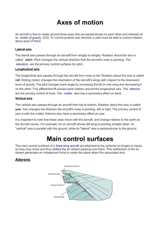
  • 1. Axes of motion An aircraft is free to rotate around three axes that are perpendicular to each other and intersect at its center of gravity (CG). To control position and direction a pilot must be able to control rotation about each of them. Lateral axis The lateral axis passes through an aircraft from wingtip to wingtip. Rotation about this axis is called pitch. Pitch changes the vertical direction that the aircraft's nose is pointing. The elevators are the primary control surfaces for pitch. Longitudinal axis The longitudinal axis passes through the aircraft from nose to tail. Rotation about this axis is called roll. Rolling motion changes the orientation of the aircraft's wings with respect to the downward force of gravity. The pilot changes bank angle by increasing the lift on one wing and decreasing it on the other. This differential lift causes bank rotation around the longitudinal axis. The ailerons are the primary control of bank. The rudder also has a secondary effect on bank. Vertical axis The vertical axis passes through an aircraft from top to bottom. Rotation about this axis is called yaw. Yaw changes the direction the aircraft's nose is pointing, left or right. The primary control of yaw is with the rudder. Ailerons also have a secondary effect on yaw. It is important to note that these axes move with the aircraft, and change relative to the earth as the aircraft moves. For example, for an aircraft whose left wing is pointing straight down, its "vertical" axis is parallel with the ground, while its "lateral" axis is perpendicular to the ground. Main control surfaces The main control surfaces of a fixed-wing aircraft are attached to the airframe on hinges or tracks so they may move and thus deflect the air stream passing over them. This redirection of the air stream generates an unbalanced force to rotate the plane about the associated axis. Ailerons
  • 2. AILERON SURFACE Ailerons are mounted on the trailing edge of each wing near the wingtips and move in opposite directions. When the pilot moves the stick left, or turns the wheel counter-clockwise, the left aileron goes up and the right aileron goes down. A raised aileron reduces lift on that wing and a lowered one increases lift, so moving the stick left causes the left wing to drop and the right wing to rise. This causes the aircraft to roll to the left and begin to turn to the left. Centering the stick returns the ailerons to neutral maintaining the bank angle. The aircraft will continue to turn until opposite aileron motion returns the bank angle to zero to fly straight. Elevator An elevator is a moveable part of the horizontal stabilizer, hinged to the back of the fixed part of the horizontal tail. The elevators move up and down together. When the pilot pulls the stick backward, the elevators go up. Pushing the stick forward causes the elevators to go down. Raised elevators push down on the tail and cause the nose to pitch up. This makes the wings fly at a higher angle of attack, which generates more lift and more drag. Centering the stick returns the elevators to neutral and stops the change of pitch. Many aircraft use a fully moveable horizontal stabilizer called stabilator or all-moving tail. Some aircraft, such as an MD-80, use a servo tab within the elevator surface to aerodynamically move the main surface into position. The direction of travel of the control tab will thus be in a direction opposite to the main control surface. It is for this reason that an MD-80 tail looks like it has a 'split' elevator system. In the canard arrangement, the elevators are hinged to the rear of a foreplane and move in the opposite sense, for example when the pilot pulls the stick back the elevators go down to increase the lift at the front and lift the nose up. Rudder The rudder is typically mounted on the trailing edge of the vertical stabilizer, part of the empennage. When the pilot pushes the left pedal, the rudder deflects left. Pushing the right pedal causes the rudder to deflect right. Deflecting the rudder right pushes the tail left and causes the nose to yaw to the right. Centering the rudder pedals returns the rudder to neutral and stops the yaw. Secondary effects of controls Ailerons The ailerons primarily control roll. Whenever lift is increased, induced drag is also increased. When the stick is moved left to roll the aircraft to the left, the right aileron is lowered which increases lift on the right wing and therefore increases induced drag on the right wing. Using ailerons causes adverse yaw, meaning the nose of the aircraft yaws in a direction opposite to the aileron application. When moving the stick to the left to bank the wings, adverse yaw moves the nose of the aircraft to the right. Adverse yaw is more pronounced for light aircraft with long wings, such as gliders. It is counteracted by the pilot with the rudder. Differential ailerons are ailerons which have been rigged such that the downgoing aileron deflects less than the upward-moving one, reducing adverse yaw.
  • 3. Rudder The rudder is a fundamental control surface which is typically controlled by pedals rather than at the stick. It is the primary means of controlling yaw--the rotation of an airplane about its vertical axis. The rudder may also be called upon to counter-act the adverse yaw produced by the roll- control surfaces. If rudder is continuously applied in level flight the aircraft will yaw initially in the direction of the applied rudder – the primary effect of rudder. After a few seconds the aircraft will tend to bank in the direction of yaw. This arises initially from the increased speed of the wing opposite to the direction of yaw and the reduced speed of the other wing. The faster wing generates more lift and so rises, while the other wing tends to go down because of generating less lift. Continued application of rudder sustains rolling tendency because the aircraft flying at an angle to the airflow - skidding towards the forward wing. When applying right rudder in an aircraft with dihedral the left hand wing will have increased angle of attack and the right hand wing will have decreased angle of attack which will result in a roll to the right. An aircraft with anhedral will show the opposite effect. This effect of the rudder is commonly used in model aircraft where if sufficient diheral or polyhedral is included in the wing design, primary roll control such as ailerons may be omitted altogether. Turning the aircraft Unlike turning a boat, turning an aircraft is not normally done with the rudder. With aircraft, the turn is caused by the horizontal component of lift. The lifting force, perpendicular to the wings of the aircraft, is tilted in the direction of the intended turn by rolling the aircraft into the turn. As the bank angle is increased, the lifting force, which was previously acting only in the vertical, is split into two components: One acting vertically and one acting horizontally. If the total lift is kept constant, the vertical component of lift will decrease. As the weight of the aircraft is unchanged, this would result in the aircraft descending if not countered. To maintain level flight requires increased positive (up) elevator to increase the angle of attack, increase the total lift generated and keep the vertical component of lift equal with the weight of the aircraft. This cannot continue indefinitely. The wings can only generate a finite amount of lift at a given air speed. As theload factor (commonly called G loading) is increased an accelerated aerodynamic stall will occur, even though the aircraft is above its 1G stall speed. The total lift (load factor) required to maintain level flight is directly related to the bank angle. This means that for a given airspeed, level flight can only be maintained up to a certain given angle of bank. Beyond this angle of bank, the aircraft will suffer an accelerated stall if the pilot attempts to generate enough lift to maintain level flight. Alternate main control surfaces Some aircraft configurations have non-standard primary controls. For example instead of elevators at the back of the stabilizers, the entire tailplane may change angle. Some aircraft have a tail in the shape of a V, and the moving parts at the back of those combine the functions of elevators and rudder. Delta wing aircraft may have "elevons" at the back of the wing, which combine the functions of elevators and ailerons.
  • 4. Secondary control surfaces Spoilers On low drag aircraft such as sailplanes, spoilers are used to disrupt airflow over the wing and greatly reduce lift. This allows a glider pilot to lose altitude without gaining excessive airspeed. Spoilers are sometimes called "lift dumpers". Spoilers that can be used asymmetrically are called spoilerons and can affect an aircraft's roll. Flaps Flaps are mounted on the trailing edge on the inboard section of each wing (near the wing roots). They are deflected down to increase the effective curvature of the wing. Flaps raise the Maximum Lift Coefficient of the aircraft and therefore reduce its stalling speed.[3] They are used during low speed, high angle of attack flight including take-off and descent for landing. Some aircraft are equipped with "flapperons", which are more commonly called "inboard ailerons"[citation needed]. These devices function primarily as ailerons, but on some aircraft, will "droop" when the flaps are deployed, thus acting as both a flap and a roll-control inboard aileron. Slats Slats, also known as leading edge devices, are extensions to the front of a wing for lift augmentation, and are intended to reduce the stalling speed by altering the airflow over the wing. Slats may be fixed or retractable - fixed slats (e.g. as on the Fieseler Fi 156 Storch) give excellent slow speed and STOL capabilities, but compromise higher speed performance. Retractable slats, as seen on most airliners, provide reduced stalling speed for take-off and landing, but are retracted for cruising. Air brakes Air brakes are used to increase drag. Spoilers might act as air brakes, but are not pure air brakes as they also function as lift-dumpers or in some cases as roll control surfaces. Air brakes are usually surfaces that deflect outwards from the fuselage (in most cases symmetrically on opposing sides) into the airstream in order to increase form-drag. As they are in most cases located elsewhere on the aircraft, they do not directly affect the lift generated by the wing. Their purpose is to slow down the aircraft. They are particularly useful when a high rate of descent is required or the aircraft velocity needs to be retarded. They are common on high performance military aircraft as well as civilian aircraft, especially those lacking reverse thrust capability. Control trimming surfaces Trimming controls allow a pilot to balance the lift and drag being produced by the wings and control surfaces over a wide range of load and airspeed. This reduces the effort required to adjust or maintain a desired flight attitude. Elevator trim Elevator trim balances the control force necessary to maintain the correct aerodynamic force on the tail to balance the aircraft. Whilst carrying out certain flight exercises, a lot of trim could be required to
  • 5. maintain the desired angle of attack. This mainly applies to slow flight, where a nose-up attitude is required, in turn requiring a lot of trim causing the tailplane to exert a strong downforce. Elevator trim is correlated with the speed of the airflow over the tail, thus airspeed changes to the aircraft require re- trimming. An important design parameter for aircraft is the stability of the aircraft when trimmed for level flight. Any disturbances such as gusts or turbulence will be damped over a short period of time and the aircraft will return to its level flight trimmed airspeed. Trimming tail plane Except for very light aircraft, trim tabs on the elevators are unable to provide the force and range of motion desired. To provide the appropriate trim force the entire horizontal tail plane is made adjustable in pitch. This allows the pilot to select exactly the right amount of positive or negative lift from the tail plane while reducing drag from the elevators. Control horn A control horn is a section of control surface which projects ahead of the pivot point. It generates a force which tends to increase the surface's deflection thus reducing the control pressure experienced by the pilot. Control horns may also incorporate a counterweight which helps to balance the control and prevent it from "fluttering" in the airstream. Some designs feature separate anti-flutter weights. (In radio controlled model aircraft, the term "control horn" has a different meaning.) and the other end of the rod connects to another control horn rigidly attached to the control surface. Spring trim In the simplest arrangement trimming is done by a mechanical spring (or bungee) which adds appropriate force to augment the pilot's control input. The spring is usually connected to an elevator trim lever to allow the pilot to set the spring force applied. Rudder and aileron trim Trim often does not only apply to the elevator, as there is also trim for the rudder and ailerons in larger aircraft. The use of this is to counter the effects of slip stream, or to counter the effects of the centre of gravity being to one side. This can be caused by a larger weight on one side of the aircraft compared to the other, such as when one fuel tank has a lot more fuel in it than the other.
  • 6. maintain the desired angle of attack. This mainly applies to slow flight, where a nose-up attitude is required, in turn requiring a lot of trim causing the tailplane to exert a strong downforce. Elevator trim is correlated with the speed of the airflow over the tail, thus airspeed changes to the aircraft require re- trimming. An important design parameter for aircraft is the stability of the aircraft when trimmed for level flight. Any disturbances such as gusts or turbulence will be damped over a short period of time and the aircraft will return to its level flight trimmed airspeed. Trimming tail plane Except for very light aircraft, trim tabs on the elevators are unable to provide the force and range of motion desired. To provide the appropriate trim force the entire horizontal tail plane is made adjustable in pitch. This allows the pilot to select exactly the right amount of positive or negative lift from the tail plane while reducing drag from the elevators. Control horn A control horn is a section of control surface which projects ahead of the pivot point. It generates a force which tends to increase the surface's deflection thus reducing the control pressure experienced by the pilot. Control horns may also incorporate a counterweight which helps to balance the control and prevent it from "fluttering" in the airstream. Some designs feature separate anti-flutter weights. (In radio controlled model aircraft, the term "control horn" has a different meaning.) and the other end of the rod connects to another control horn rigidly attached to the control surface. Spring trim In the simplest arrangement trimming is done by a mechanical spring (or bungee) which adds appropriate force to augment the pilot's control input. The spring is usually connected to an elevator trim lever to allow the pilot to set the spring force applied. Rudder and aileron trim Trim often does not only apply to the elevator, as there is also trim for the rudder and ailerons in larger aircraft. The use of this is to counter the effects of slip stream, or to counter the effects of the centre of gravity being to one side. This can be caused by a larger weight on one side of the aircraft compared to the other, such as when one fuel tank has a lot more fuel in it than the other.