SlideShare ist ein Scribd-Unternehmen logo
1 von 22
Downloaden Sie, um offline zu lesen
An OR Operation   In this example an OR operation is used in network 1. It can be
                  seen that if either input I0.2 (input 3) or (O in the statement list)
                  input I0.3 (input 4), or both are true, then output Q0.1 (output 2)
                  will be true.


                  Another way to see how an OR function works is with a
                  Boolean logic diagram. The symbol differs slightly from an AND
                  function. The OR function is represented by a number of inputs
                  on the left side. In this case there are two inputs. The output is
                  represented on the right side. It can be seen from the table that
                  any input can be a logic 1 in order for the output to be a logic 1.


                               Or (O) Function                       Or (O) Function

                  Input 3                                   I0.4
                                                 Output 2                                 Q0.1
                  Input 4                                   I0.5


                     Input 3     Input 4    Output 2          I0.4         I0.5        Q0.1
                        0           0          0                0            0          0
                        0           1          1                0            1          1
                        1           0          1                1            0          1
                        1           1          1                1            1          1


                                                                                                 45
Testing a Program   Once a program has been written it needs to be tested and
                    debugged. One way this can be done is to simulate the field
                    inputs with an input simulator, such as the one made for the
                    S7-200. The program is first downloaded from the programming
                    device to the CPU. The selector switch is placed in the RUN
                    position. The simulator switches are operated and the resulting
                    indication is observed on the output status indicator lamps.


Status Functions    After a program has been loaded and is running in the PLC, the
                    actual status of ladder elements can be monitored using STEP
                    7 Micro/WIN32 software. The standard method of showing a
                    ladder element is by indicating the circuit condition it produces
                    when the device is in the deenergized or non operated state.
                    In the following illustration input 1 (I0.0) is programmed as a
                    normally open (NO) contact. In this condition, power will not
                    flow through the contacts to the output (Q0.0).


46
When viewing the ladder diagram in the status mode, control
          elements that are active, or true (logic 1), are highlighted. In the
          example shown the toggle switch connected to input 1 has
          been closed. Power can now flow through the control element
          associated with input 1 (I0.0) and activate the output (Q0.0). The
          lamp will illuminate.


Forcing   Forcing is another useful tool in the commissioning of an
          application. It can be used to temporarily override the input
          or output status of the application in order to test and debug
          the program. The force function can also be used to override
          discrete output points. The force function can be used to skip
          portions of a program by enabling a jump instruction with a
          forced memory bit. Under normal circumstances the toggle
          switch, shown in the illustration below, would have to be closed
          to enable input 1 (I0.0) and turn on the output light. Forcing
          enables input 1 even though the input toggle switch is open.
          With input 1 forced high the output light will illuminate. When
          a function is forced the control bit identifier is highlighted. The
          element is also highlighted because it is on.


                                                                           47
The following table shows the appearance of ladder elements in
     the Off, forced, and On condition.


48
Discrete Inputs/Outputs


         To understand discrete control of a programmable controller the
         same simple lamp circuit illustrated with forcing will be used.
         This is only for instructional purposes as a circuit this simple
         would not require a programmable controller. In this example
         the lamp is off when the switch is open and on when the
         switch is closed.


Wiring   To accomplish this task, a switch is wired to the input of the
         PLC and an indicator light is wired to output terminal.


           Light


                      Switch


                                                                          49
The following drawing illustrates the sequence of events. A
                      switch is wired to the input module of the PLC. A lamp is wired
                      to the output module. The program is in the CPU. The CPU
                      scans the inputs. When it finds the switch open I0.0 receives
                      a binary 0. This instructs Q0.0 to send a binary 0 to the output
                      module. The lamp is off. When it finds the switch closed I0.0
                      receives a binary 1. This instructs Q0.0 to send a binary 1 to the
                      output module, turning on the lamp.


Program Instruction   When the switch is open the CPU receives a logic 0 from input
                      I0.0. The CPU sends a logic 0 to output Q0.0 and the light is off.


                      When the switch is closed the CPU receives a logic 1 from
                      input I0.0. The CPU sends a logic 1 to output Q0.0, thus
                      activating Q0.0. The light turns on.


50
Motor Starter Example   The following example involves a motor start and stop circuit.
                        The line diagram illustrates how a normally open and a
                        normally closed pushbutton might be used in a control circuit.
                        In this example a motor started (M) is wired in series with
                        a normally open momentary pushbutton (Start), a normally
                        closed momentary pushbutton (Stop), and the normally closed
                        contacts of an overload relay (OL).


                        Momentarily depressing the Start pushbutton completes the
                        path of current flow and energizes the motor starter (M).


                                                                                     51
This closes the associated M and Ma (auxiliary contact located
     in the motor starter) contacts. When the Start button is released
     a holding circuit exists to the M contactor through the auxiliary
     contacts Ma. The motor will run until the normally closed
     Stop button is depressed, or the overload relay opens the OL
     contacts, breaking the path of current flow to the motor starter
     and opening the associated M and Ma contacts.


     This control task can also be accomplished with a PLC.


                Motor Starter
                 (Actuator)


                   Output
                                                         Motor


          PLC


                                Input   Start/Stop Pushbuttons
                                               (Sensors)


52
Program Instruction   A normally open Start pushbutton is wired to the first input
                      (I0.0), a normally closed Stop pushbutton is wired to the second
                      input (I0.1), and normally closed overload relay contacts (part
                      of the motor starter) are connected to the third input (I0.2).
                      The first input (I0.0), second input (I0.1), and third input (I0.2)
                      form an AND circuit and are used to control normally open
                      programming function contacts on Network 1. I0.1 status bit is
                      a logic 1 because the normally closed (NC) Stop Pushbutton is
                      closed. I0.2 status bit is a logic 1 because the normally closed
                      (NC) overload relay (OL) contacts are closed. Output Q0.0 is
                      also programmed on Network 1. In addition, a normally open set
                      of contacts associated with Q0.0 is programmed on Network
                      1 to form an OR circuit. A motor starter is connected to output
                      Q0.0.


                      When the Start pushbutton is depressed the CPU receives a
                      logic 1 from input I0.0. This causes the I0.0 contact to close.
                      All three inputs are now a logic 1. The CPU sends a logic 1
                      to output Q0.0. The motor starter is energized and the motor
                      starts.


                                                                                        53
When the Start pushbutton is pressed, output Q0.0 is now
     true and on the next scan, when normally open contact Q0.0 is
     solved, the contact will close and output Q0.0 will stay on even
     if the Start pushbutton has been released.


     The motor will continue to run until the Stop pushbutton is
     depressed. Input I0.1 will now be a logic 0 (false). The CPU will
     send a binary 0 to output Q0.0. The motor will turn off.


54
When the Stop pushbutton is released I0.1 logic function will
                            again be true and the program ready for the next time the Start
                            pushbutton is pressed.


Expanding the Application   The application can be easily expanded to include indicator
                            lights for RUN and STOP conditions. In this example a RUN
                            indicator light is connected to output Q0.1 and a STOP indicator
                            light is connected to output Q0.2.


                                     Motor Starter
                                      (Actuator)


                                                                                  Motor
                                Output               Indicator Lights


                                  PLC


                                                        Input           Start/Stop Pushbuttons
                                                                               (Sensors)


                                                                                                 55
It can be seen from the ladder logic that a normally open output
     Q0.0 is connected on Network 2 to output Q0.1 and a normally
     closed Q0.0 contact is connected to output Q0.2 on network
     3. In a stopped condition output Q0.0 is off. The normally open
     Q0.0 contacts on Network 2 are open and the RUN indicator,
     connected to output Q0.1 light is off. The normally closed Q0.1
     on Network 3 lights are closed and the STOP indicator light,
     connected to output Q0.2 is on.


56
When the PLC starts the motor output Q0.0 is now a logic
                        high (On). The normally open Q0.0 contacts on Network 2 now
                        switch to a logic 1 (closed) and output Q0.1 turns the RUN
                        indicator on. The normally closed Q0.0 contacts on Network
                        3 switch to a logic 0 (open) and the STOP indicator light
                        connected to output Q0.2 is now off.


Adding a Limit Switch   The application can be further expanded by adding a limit
                        switch with normally open contacts to input I0.3.


                                 Motor Starter
                                  (Actuator)


                                                                                 Motor
                            Output                  Indicator Lights


                              PLC


                                                       Input           Start/Stop Pushbuttons
                                                                              (Sensors)
                                     Limit Switch


                                                                                                57
A limit switch could be used to stop the motor or prevent the
     motor from being started. An access door to the motor, or its
     associated equipment, is one example of a limit switch’s use.
     If the access door is open, the normally open contacts of LS1
     connected to input I0.3 are open and the motor will not start.


     When the access door is closed, the normally open contacts on
     the limit switch (LS1) are closed. Input I0.3 is now on (logic 1),
     and the motor will start when the Start pushbutton is pressed.


58
Expansion   The PLC program can be expanded to accommodate many
            commercial and industrial applications. Additional Start/Stop
            pushbuttons and indicator lights can be added for remote
            operation, or control of a second motor starter and motor.
            Overtravel limit switches can be added along with proximity
            switches for sensing object position. In addition, expansion
            modules can be added to further increase the I/O capability. The
            applications are only limited by the number of I/Os and amount
            of memory available on the PLC.


             Motor Starters
            (Digital Outputs)


                        Indicator Lights
                       (Digital Outputs)


                                           I/O Expansion Module


                        Pushbuttons
                       (Digital Inputs)                   Sensors
                                                       (Digital Inputs)


                                                                          59
Review 4
           1.   Identify the following symbols:


                a. ____________


                b. ____________


                c. ____________


           2.   Complete the following tables:


           3.   In the following instruction Q0.0 will be true (logic 1)
                when ____________ or ____________ is true, and when
                ____________ is true.


60
Analog Inputs and Outputs


PLCs must also work with continuous or analog signals. Typical
analog signals are 0 - 10 VDC or 4 - 20 mA. Analog signals are
used to represent changing values such as speed, temperature,
weight, and level. A PLC cannot process these signals in
an analog form. The PLC must convert the analog signal
into a digital representation. An expansion module, capable
of converting the analog signal, must be used. The S7-200
analog modules convert standard voltage and current analog
values into a 12-bit digital representation. The digital values are
transferred to the PLC for use in register or word locations.

In addition, analog modules are available for use with
thermocouple and RTD type sensors used in to achieve a high
level of accuracy in temperature measurement.


     SF/DIAG


                                        Analog Expansion Module


                                                                  61
Application Example   A field device that measures a varying value is typically
                      connected to a transducer. In the following example a scale
                      is connected to a load cell. A load cell is a device that takes a
                      varying value and converts it to a variable voltage or current
                      output. In this example the load cell is converting a value of
                      weight into a 0 - 10 VDC output. The output value depends
                      entirely on the manufactured specifications for the device. This
                      load cell outputs 0 - 10 VDC for a 0 - 500 Lbs input. The 0 - 10
                      VDC load cell output is connected to the input of an analog
                      expansion module.


                      The example application can be expanded to include a conveyor
                      system with a gate to direct packages of varying weight.
                      As packages move along the conveyor they are weighed. A
                      package that weighs at or greater than a specified value is
                      routed along one conveyor path. A package that weighs less
                      than a specified value is routed along another conveyor path,
                      where it will later be inspected for missing contents.


62
Analog Outputs   Analog outputs are used in applications requiring control
                 capability of field devices which respond to continuous voltage
                 or current levels. Analog outputs may be used as a variable
                 reference for control valves, chart recorders, electric motor
                 drives, analog meters, and pressure transducers. Like analog
                 inputs, analog outputs are generally connected to a controlling
                 device through a transducer. The transducer takes the voltage
                 signal and, depending on the requirement, amplifies, reduces,
                 or changes it into another signal which controls the device. In
                 the following example a 0 - 10 VDC signal controls a 0 - 500 Lbs.
                 scale analog meter.


                                                                               63
Timers


     Timers are devices that count increments of time. Traffic lights
     are one example where timers are used. In this example timers
     are used to control the length of time between signal changes.


     Timers are represented by boxes in ladder logic. When a timer
     receives an enable, the timer starts to time. The timer compares
     its current time with the preset time. The output of the timer
     is a logic 0 as long as the current time is less than the preset
     time. When the current time is greater than the preset time the
     timer output is a logic 1. S7-200 uses three types of timers: On-
     Delay (TON), Retentive On-Delay (TONR), and Off-Delay (TOF).


64
S7-200 Timers               S7-200 timers are provided with resolutions of 1 millisecond,
                            10 milliseconds, and 100 milliseconds. The maximum value of
                            these timers is 32.767 seconds, 327 seconds, and 3276.7
                                                                .67
                            seconds, respectively. By adding program elements, logic can
                            be programmed for much greater time intervals.

Hard-Wired Timing Circuit   Timers used with PLCs can be compared to timing circuits used
                            in hard-wired control line diagrams. In the following example, a
                            normally open (NO) switch (S1) is used with a timer (TR1). For
                            this example the timer has been set for 5 seconds. When S1
                            is closed, TR1 begins timing. When 5 seconds have elapsed,
                            TR1 will close its associated normally open TR1 contacts,
                            illuminating pilot light PL1. When S1 is open, deenergizing TR1,
                            the TR1 contacts open, immediately extinguishing PL1. This type
                            of timer is referred to as ON delay. ON delay indicates that once
                            a timer receives an enable signal, a predetermined amount of
                            time (set by the timer) must pass before the timer’s contacts
                            change state.


On-Delay (TON)              When the On-Delay timer (TON) receives an enable (logic 1) at
                            its input (IN), a predetermined amount of time (preset time - PT)
                            passes before the timer bit (T-bit) turns on. The T-bit is a logic
                            function internal to the timer and is not shown on the symbol.
                            The timer resets to the starting time when the enabling input
                            goes to a logic 0.


                                                                                           65
In the following simple timer example, a switch is connected to
     input I0.3, and a light is connected to output Q0.1.


     When the switch is closed input 4 becomes a logic 1, which
     is loaded into timer T37 T37 has a time base of 100 ms (.100
                             .
     seconds). The preset time (PT) value has been set to 150. This
     is equivalent to 15 seconds (.100 x 150 ). The light will turn on
     15 seconds after the input switch is closed. If the switch were
     opened before 15 seconds had passed, then reclosed, the timer
     would again begin timing at 0.


          I0.3                                    T37

                                             IN         TON


                                  150        PT


          T37                                      Q0.1


66

Weitere ähnliche Inhalte

Was ist angesagt?

Ec2308 mini project
Ec2308 mini projectEc2308 mini project
Ec2308 mini project
unnimaya_k
 
8449972 embedded-systems-and-model-of-metro-train
8449972 embedded-systems-and-model-of-metro-train8449972 embedded-systems-and-model-of-metro-train
8449972 embedded-systems-and-model-of-metro-train
Jitendra Saroj
 

Was ist angesagt? (20)

8051 interrupts
8051 interrupts8051 interrupts
8051 interrupts
 
I/O Ports
I/O Ports I/O Ports
I/O Ports
 
Freescale Microcontroller programming
Freescale Microcontroller programmingFreescale Microcontroller programming
Freescale Microcontroller programming
 
Micro controller 8051 Interrupts
Micro controller 8051 InterruptsMicro controller 8051 Interrupts
Micro controller 8051 Interrupts
 
Class8
Class8Class8
Class8
 
Programmable Logic Controller | Ladder Logic diagrams| Block diagram | I/O Mo...
Programmable Logic Controller | Ladder Logic diagrams| Block diagram | I/O Mo...Programmable Logic Controller | Ladder Logic diagrams| Block diagram | I/O Mo...
Programmable Logic Controller | Ladder Logic diagrams| Block diagram | I/O Mo...
 
Microcontroller ppt
Microcontroller pptMicrocontroller ppt
Microcontroller ppt
 
8051 Microcontroller I/O ports
8051 Microcontroller I/O ports8051 Microcontroller I/O ports
8051 Microcontroller I/O ports
 
Interrupts programming in embedded C using 8051
Interrupts programming in embedded C using 8051Interrupts programming in embedded C using 8051
Interrupts programming in embedded C using 8051
 
8051
80518051
8051
 
At89c2051 Data sheet
At89c2051 Data sheetAt89c2051 Data sheet
At89c2051 Data sheet
 
8051 MICROCONTROLLER
8051 MICROCONTROLLER 8051 MICROCONTROLLER
8051 MICROCONTROLLER
 
Final Presentation
Final PresentationFinal Presentation
Final Presentation
 
Ec2308 mini project
Ec2308 mini projectEc2308 mini project
Ec2308 mini project
 
Mcapptunitvii
McapptunitviiMcapptunitvii
Mcapptunitvii
 
Plc operation part 2
Plc operation part 2Plc operation part 2
Plc operation part 2
 
8449972 embedded-systems-and-model-of-metro-train
8449972 embedded-systems-and-model-of-metro-train8449972 embedded-systems-and-model-of-metro-train
8449972 embedded-systems-and-model-of-metro-train
 
Omron ladder programming
Omron ladder programmingOmron ladder programming
Omron ladder programming
 
Plc programming course1
Plc programming course1Plc programming course1
Plc programming course1
 
Automatic Garage System using VHDL
Automatic Garage System using VHDLAutomatic Garage System using VHDL
Automatic Garage System using VHDL
 

Ähnlich wie Plc operation part 3

08 chapter03 06_status_bits_otl_otu_scan_logic_fa16
08 chapter03 06_status_bits_otl_otu_scan_logic_fa1608 chapter03 06_status_bits_otl_otu_scan_logic_fa16
08 chapter03 06_status_bits_otl_otu_scan_logic_fa16
John Todora
 
PLC Circuit Design And Basic Programming By Manish kumar
PLC Circuit Design And Basic Programming By Manish kumarPLC Circuit Design And Basic Programming By Manish kumar
PLC Circuit Design And Basic Programming By Manish kumar
manishkumarm
 
digitalelectronicslogicfamilies-190628101225-converted.pptx
digitalelectronicslogicfamilies-190628101225-converted.pptxdigitalelectronicslogicfamilies-190628101225-converted.pptx
digitalelectronicslogicfamilies-190628101225-converted.pptx
BijaySharma51
 
Components logic gates
Components   logic gatesComponents   logic gates
Components logic gates
sld1950
 

Ähnlich wie Plc operation part 3 (20)

PLC HO4.pdf
PLC HO4.pdfPLC HO4.pdf
PLC HO4.pdf
 
BASIC COMPONENTS OF PLC NEW.ppt
BASIC COMPONENTS OF PLC NEW.pptBASIC COMPONENTS OF PLC NEW.ppt
BASIC COMPONENTS OF PLC NEW.ppt
 
08 chapter03 06_status_bits_otl_otu_scan_logic_fa16
08 chapter03 06_status_bits_otl_otu_scan_logic_fa1608 chapter03 06_status_bits_otl_otu_scan_logic_fa16
08 chapter03 06_status_bits_otl_otu_scan_logic_fa16
 
PLC arithmatic functions
PLC arithmatic functionsPLC arithmatic functions
PLC arithmatic functions
 
Vt plc
Vt plcVt plc
Vt plc
 
Plc ppt
Plc pptPlc ppt
Plc ppt
 
Automation and Robotics 20ME51I_Week_2_Practicals.pdf
Automation and Robotics 20ME51I_Week_2_Practicals.pdfAutomation and Robotics 20ME51I_Week_2_Practicals.pdf
Automation and Robotics 20ME51I_Week_2_Practicals.pdf
 
PLC Circuit Design And Basic Programming By Manish kumar
PLC Circuit Design And Basic Programming By Manish kumarPLC Circuit Design And Basic Programming By Manish kumar
PLC Circuit Design And Basic Programming By Manish kumar
 
Sequential Logic
Sequential LogicSequential Logic
Sequential Logic
 
digitalelectronicslogicfamilies-190628101225-converted.pptx
digitalelectronicslogicfamilies-190628101225-converted.pptxdigitalelectronicslogicfamilies-190628101225-converted.pptx
digitalelectronicslogicfamilies-190628101225-converted.pptx
 
Components logic gates
Components   logic gatesComponents   logic gates
Components logic gates
 
Lab no 4
Lab no 4Lab no 4
Lab no 4
 
Programmable Logic Controller
Programmable Logic ControllerProgrammable Logic Controller
Programmable Logic Controller
 
Beptu induction cooker_ha0101_e
Beptu induction cooker_ha0101_eBeptu induction cooker_ha0101_e
Beptu induction cooker_ha0101_e
 
Digital electronics logic families
Digital electronics logic familiesDigital electronics logic families
Digital electronics logic families
 
Logic gates (1)
Logic gates (1)Logic gates (1)
Logic gates (1)
 
bếp từ Ha0101ev120
bếp từ   Ha0101ev120bếp từ   Ha0101ev120
bếp từ Ha0101ev120
 
Ladder
LadderLadder
Ladder
 
Or gate
Or gateOr gate
Or gate
 
Ladder Intro Tutorial
Ladder Intro TutorialLadder Intro Tutorial
Ladder Intro Tutorial
 

Mehr von Sakshi Vashist

400 challenging puzzles
400 challenging puzzles400 challenging puzzles
400 challenging puzzles
Sakshi Vashist
 
Aptitude testing puzzles for freshers
Aptitude testing puzzles for freshersAptitude testing puzzles for freshers
Aptitude testing puzzles for freshers
Sakshi Vashist
 
About ballarpur industries limited
About ballarpur industries limitedAbout ballarpur industries limited
About ballarpur industries limited
Sakshi Vashist
 

Mehr von Sakshi Vashist (20)

Puzzles to puzzle you
Puzzles to puzzle youPuzzles to puzzle you
Puzzles to puzzle you
 
Mind blowing puzzles
Mind blowing puzzlesMind blowing puzzles
Mind blowing puzzles
 
400 challenging puzzles
400 challenging puzzles400 challenging puzzles
400 challenging puzzles
 
400 infy puzzles
400 infy puzzles400 infy puzzles
400 infy puzzles
 
Aptitude testing puzzles for freshers
Aptitude testing puzzles for freshersAptitude testing puzzles for freshers
Aptitude testing puzzles for freshers
 
MCC Motor Control Center 4
MCC Motor Control Center 4MCC Motor Control Center 4
MCC Motor Control Center 4
 
MCC Motor Control Center 3
MCC Motor Control Center 3MCC Motor Control Center 3
MCC Motor Control Center 3
 
MCC Motor Control Center 2
MCC Motor Control Center 2MCC Motor Control Center 2
MCC Motor Control Center 2
 
MCC Motor Control Center 1
MCC Motor Control Center 1MCC Motor Control Center 1
MCC Motor Control Center 1
 
Residential Surge Protection 3
Residential Surge Protection 3Residential Surge Protection 3
Residential Surge Protection 3
 
Residential Surge Protection 2
Residential Surge Protection 2Residential Surge Protection 2
Residential Surge Protection 2
 
Residential Surge Protection 1
Residential Surge Protection 1Residential Surge Protection 1
Residential Surge Protection 1
 
Tg turbine
Tg turbineTg turbine
Tg turbine
 
variable frequency drive (VFD) installation
variable frequency drive (VFD) installationvariable frequency drive (VFD) installation
variable frequency drive (VFD) installation
 
Power plant instrumentation
Power plant instrumentationPower plant instrumentation
Power plant instrumentation
 
All about paper making process
All about paper making processAll about paper making process
All about paper making process
 
About ballarpur industries limited
About ballarpur industries limitedAbout ballarpur industries limited
About ballarpur industries limited
 
Basics of an ac drive - with motor basics
Basics of an ac drive - with motor basicsBasics of an ac drive - with motor basics
Basics of an ac drive - with motor basics
 
Power saving ideas implemented practically
Power saving ideas implemented practicallyPower saving ideas implemented practically
Power saving ideas implemented practically
 
Boiler operation
Boiler operationBoiler operation
Boiler operation
 

Kürzlich hochgeladen

Architecting Cloud Native Applications
Architecting Cloud Native ApplicationsArchitecting Cloud Native Applications
Architecting Cloud Native Applications
WSO2
 

Kürzlich hochgeladen (20)

Apidays New York 2024 - Passkeys: Developing APIs to enable passwordless auth...
Apidays New York 2024 - Passkeys: Developing APIs to enable passwordless auth...Apidays New York 2024 - Passkeys: Developing APIs to enable passwordless auth...
Apidays New York 2024 - Passkeys: Developing APIs to enable passwordless auth...
 
Cyberprint. Dark Pink Apt Group [EN].pdf
Cyberprint. Dark Pink Apt Group [EN].pdfCyberprint. Dark Pink Apt Group [EN].pdf
Cyberprint. Dark Pink Apt Group [EN].pdf
 
Exploring Multimodal Embeddings with Milvus
Exploring Multimodal Embeddings with MilvusExploring Multimodal Embeddings with Milvus
Exploring Multimodal Embeddings with Milvus
 
Biography Of Angeliki Cooney | Senior Vice President Life Sciences | Albany, ...
Biography Of Angeliki Cooney | Senior Vice President Life Sciences | Albany, ...Biography Of Angeliki Cooney | Senior Vice President Life Sciences | Albany, ...
Biography Of Angeliki Cooney | Senior Vice President Life Sciences | Albany, ...
 
AWS Community Day CPH - Three problems of Terraform
AWS Community Day CPH - Three problems of TerraformAWS Community Day CPH - Three problems of Terraform
AWS Community Day CPH - Three problems of Terraform
 
Exploring the Future Potential of AI-Enabled Smartphone Processors
Exploring the Future Potential of AI-Enabled Smartphone ProcessorsExploring the Future Potential of AI-Enabled Smartphone Processors
Exploring the Future Potential of AI-Enabled Smartphone Processors
 
Emergent Methods: Multi-lingual narrative tracking in the news - real-time ex...
Emergent Methods: Multi-lingual narrative tracking in the news - real-time ex...Emergent Methods: Multi-lingual narrative tracking in the news - real-time ex...
Emergent Methods: Multi-lingual narrative tracking in the news - real-time ex...
 
Apidays New York 2024 - Scaling API-first by Ian Reasor and Radu Cotescu, Adobe
Apidays New York 2024 - Scaling API-first by Ian Reasor and Radu Cotescu, AdobeApidays New York 2024 - Scaling API-first by Ian Reasor and Radu Cotescu, Adobe
Apidays New York 2024 - Scaling API-first by Ian Reasor and Radu Cotescu, Adobe
 
Apidays New York 2024 - Accelerating FinTech Innovation by Vasa Krishnan, Fin...
Apidays New York 2024 - Accelerating FinTech Innovation by Vasa Krishnan, Fin...Apidays New York 2024 - Accelerating FinTech Innovation by Vasa Krishnan, Fin...
Apidays New York 2024 - Accelerating FinTech Innovation by Vasa Krishnan, Fin...
 
Repurposing LNG terminals for Hydrogen Ammonia: Feasibility and Cost Saving
Repurposing LNG terminals for Hydrogen Ammonia: Feasibility and Cost SavingRepurposing LNG terminals for Hydrogen Ammonia: Feasibility and Cost Saving
Repurposing LNG terminals for Hydrogen Ammonia: Feasibility and Cost Saving
 
Connector Corner: Accelerate revenue generation using UiPath API-centric busi...
Connector Corner: Accelerate revenue generation using UiPath API-centric busi...Connector Corner: Accelerate revenue generation using UiPath API-centric busi...
Connector Corner: Accelerate revenue generation using UiPath API-centric busi...
 
TrustArc Webinar - Unlock the Power of AI-Driven Data Discovery
TrustArc Webinar - Unlock the Power of AI-Driven Data DiscoveryTrustArc Webinar - Unlock the Power of AI-Driven Data Discovery
TrustArc Webinar - Unlock the Power of AI-Driven Data Discovery
 
CNIC Information System with Pakdata Cf In Pakistan
CNIC Information System with Pakdata Cf In PakistanCNIC Information System with Pakdata Cf In Pakistan
CNIC Information System with Pakdata Cf In Pakistan
 
Polkadot JAM Slides - Token2049 - By Dr. Gavin Wood
Polkadot JAM Slides - Token2049 - By Dr. Gavin WoodPolkadot JAM Slides - Token2049 - By Dr. Gavin Wood
Polkadot JAM Slides - Token2049 - By Dr. Gavin Wood
 
ProductAnonymous-April2024-WinProductDiscovery-MelissaKlemke
ProductAnonymous-April2024-WinProductDiscovery-MelissaKlemkeProductAnonymous-April2024-WinProductDiscovery-MelissaKlemke
ProductAnonymous-April2024-WinProductDiscovery-MelissaKlemke
 
[BuildWithAI] Introduction to Gemini.pdf
[BuildWithAI] Introduction to Gemini.pdf[BuildWithAI] Introduction to Gemini.pdf
[BuildWithAI] Introduction to Gemini.pdf
 
MINDCTI Revenue Release Quarter One 2024
MINDCTI Revenue Release Quarter One 2024MINDCTI Revenue Release Quarter One 2024
MINDCTI Revenue Release Quarter One 2024
 
Web Form Automation for Bonterra Impact Management (fka Social Solutions Apri...
Web Form Automation for Bonterra Impact Management (fka Social Solutions Apri...Web Form Automation for Bonterra Impact Management (fka Social Solutions Apri...
Web Form Automation for Bonterra Impact Management (fka Social Solutions Apri...
 
DBX First Quarter 2024 Investor Presentation
DBX First Quarter 2024 Investor PresentationDBX First Quarter 2024 Investor Presentation
DBX First Quarter 2024 Investor Presentation
 
Architecting Cloud Native Applications
Architecting Cloud Native ApplicationsArchitecting Cloud Native Applications
Architecting Cloud Native Applications
 

Plc operation part 3

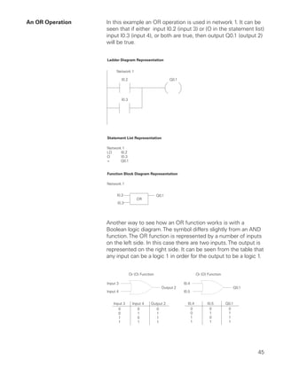
  • 1. An OR Operation In this example an OR operation is used in network 1. It can be seen that if either input I0.2 (input 3) or (O in the statement list) input I0.3 (input 4), or both are true, then output Q0.1 (output 2) will be true. Another way to see how an OR function works is with a Boolean logic diagram. The symbol differs slightly from an AND function. The OR function is represented by a number of inputs on the left side. In this case there are two inputs. The output is represented on the right side. It can be seen from the table that any input can be a logic 1 in order for the output to be a logic 1. Or (O) Function Or (O) Function Input 3 I0.4 Output 2 Q0.1 Input 4 I0.5 Input 3 Input 4 Output 2 I0.4 I0.5 Q0.1 0 0 0 0 0 0 0 1 1 0 1 1 1 0 1 1 0 1 1 1 1 1 1 1 45
  • 2. Testing a Program Once a program has been written it needs to be tested and debugged. One way this can be done is to simulate the field inputs with an input simulator, such as the one made for the S7-200. The program is first downloaded from the programming device to the CPU. The selector switch is placed in the RUN position. The simulator switches are operated and the resulting indication is observed on the output status indicator lamps. Status Functions After a program has been loaded and is running in the PLC, the actual status of ladder elements can be monitored using STEP 7 Micro/WIN32 software. The standard method of showing a ladder element is by indicating the circuit condition it produces when the device is in the deenergized or non operated state. In the following illustration input 1 (I0.0) is programmed as a normally open (NO) contact. In this condition, power will not flow through the contacts to the output (Q0.0). 46
  • 3. When viewing the ladder diagram in the status mode, control elements that are active, or true (logic 1), are highlighted. In the example shown the toggle switch connected to input 1 has been closed. Power can now flow through the control element associated with input 1 (I0.0) and activate the output (Q0.0). The lamp will illuminate. Forcing Forcing is another useful tool in the commissioning of an application. It can be used to temporarily override the input or output status of the application in order to test and debug the program. The force function can also be used to override discrete output points. The force function can be used to skip portions of a program by enabling a jump instruction with a forced memory bit. Under normal circumstances the toggle switch, shown in the illustration below, would have to be closed to enable input 1 (I0.0) and turn on the output light. Forcing enables input 1 even though the input toggle switch is open. With input 1 forced high the output light will illuminate. When a function is forced the control bit identifier is highlighted. The element is also highlighted because it is on. 47
  • 4. The following table shows the appearance of ladder elements in the Off, forced, and On condition. 48
  • 5. Discrete Inputs/Outputs To understand discrete control of a programmable controller the same simple lamp circuit illustrated with forcing will be used. This is only for instructional purposes as a circuit this simple would not require a programmable controller. In this example the lamp is off when the switch is open and on when the switch is closed. Wiring To accomplish this task, a switch is wired to the input of the PLC and an indicator light is wired to output terminal. Light Switch 49
  • 6. The following drawing illustrates the sequence of events. A switch is wired to the input module of the PLC. A lamp is wired to the output module. The program is in the CPU. The CPU scans the inputs. When it finds the switch open I0.0 receives a binary 0. This instructs Q0.0 to send a binary 0 to the output module. The lamp is off. When it finds the switch closed I0.0 receives a binary 1. This instructs Q0.0 to send a binary 1 to the output module, turning on the lamp. Program Instruction When the switch is open the CPU receives a logic 0 from input I0.0. The CPU sends a logic 0 to output Q0.0 and the light is off. When the switch is closed the CPU receives a logic 1 from input I0.0. The CPU sends a logic 1 to output Q0.0, thus activating Q0.0. The light turns on. 50
  • 7. Motor Starter Example The following example involves a motor start and stop circuit. The line diagram illustrates how a normally open and a normally closed pushbutton might be used in a control circuit. In this example a motor started (M) is wired in series with a normally open momentary pushbutton (Start), a normally closed momentary pushbutton (Stop), and the normally closed contacts of an overload relay (OL). Momentarily depressing the Start pushbutton completes the path of current flow and energizes the motor starter (M). 51
  • 8. This closes the associated M and Ma (auxiliary contact located in the motor starter) contacts. When the Start button is released a holding circuit exists to the M contactor through the auxiliary contacts Ma. The motor will run until the normally closed Stop button is depressed, or the overload relay opens the OL contacts, breaking the path of current flow to the motor starter and opening the associated M and Ma contacts. This control task can also be accomplished with a PLC. Motor Starter (Actuator) Output Motor PLC Input Start/Stop Pushbuttons (Sensors) 52
  • 9. Program Instruction A normally open Start pushbutton is wired to the first input (I0.0), a normally closed Stop pushbutton is wired to the second input (I0.1), and normally closed overload relay contacts (part of the motor starter) are connected to the third input (I0.2). The first input (I0.0), second input (I0.1), and third input (I0.2) form an AND circuit and are used to control normally open programming function contacts on Network 1. I0.1 status bit is a logic 1 because the normally closed (NC) Stop Pushbutton is closed. I0.2 status bit is a logic 1 because the normally closed (NC) overload relay (OL) contacts are closed. Output Q0.0 is also programmed on Network 1. In addition, a normally open set of contacts associated with Q0.0 is programmed on Network 1 to form an OR circuit. A motor starter is connected to output Q0.0. When the Start pushbutton is depressed the CPU receives a logic 1 from input I0.0. This causes the I0.0 contact to close. All three inputs are now a logic 1. The CPU sends a logic 1 to output Q0.0. The motor starter is energized and the motor starts. 53
  • 10. When the Start pushbutton is pressed, output Q0.0 is now true and on the next scan, when normally open contact Q0.0 is solved, the contact will close and output Q0.0 will stay on even if the Start pushbutton has been released. The motor will continue to run until the Stop pushbutton is depressed. Input I0.1 will now be a logic 0 (false). The CPU will send a binary 0 to output Q0.0. The motor will turn off. 54
  • 11. When the Stop pushbutton is released I0.1 logic function will again be true and the program ready for the next time the Start pushbutton is pressed. Expanding the Application The application can be easily expanded to include indicator lights for RUN and STOP conditions. In this example a RUN indicator light is connected to output Q0.1 and a STOP indicator light is connected to output Q0.2. Motor Starter (Actuator) Motor Output Indicator Lights PLC Input Start/Stop Pushbuttons (Sensors) 55
  • 12. It can be seen from the ladder logic that a normally open output Q0.0 is connected on Network 2 to output Q0.1 and a normally closed Q0.0 contact is connected to output Q0.2 on network 3. In a stopped condition output Q0.0 is off. The normally open Q0.0 contacts on Network 2 are open and the RUN indicator, connected to output Q0.1 light is off. The normally closed Q0.1 on Network 3 lights are closed and the STOP indicator light, connected to output Q0.2 is on. 56
  • 13. When the PLC starts the motor output Q0.0 is now a logic high (On). The normally open Q0.0 contacts on Network 2 now switch to a logic 1 (closed) and output Q0.1 turns the RUN indicator on. The normally closed Q0.0 contacts on Network 3 switch to a logic 0 (open) and the STOP indicator light connected to output Q0.2 is now off. Adding a Limit Switch The application can be further expanded by adding a limit switch with normally open contacts to input I0.3. Motor Starter (Actuator) Motor Output Indicator Lights PLC Input Start/Stop Pushbuttons (Sensors) Limit Switch 57
  • 14. A limit switch could be used to stop the motor or prevent the motor from being started. An access door to the motor, or its associated equipment, is one example of a limit switch’s use. If the access door is open, the normally open contacts of LS1 connected to input I0.3 are open and the motor will not start. When the access door is closed, the normally open contacts on the limit switch (LS1) are closed. Input I0.3 is now on (logic 1), and the motor will start when the Start pushbutton is pressed. 58
  • 15. Expansion The PLC program can be expanded to accommodate many commercial and industrial applications. Additional Start/Stop pushbuttons and indicator lights can be added for remote operation, or control of a second motor starter and motor. Overtravel limit switches can be added along with proximity switches for sensing object position. In addition, expansion modules can be added to further increase the I/O capability. The applications are only limited by the number of I/Os and amount of memory available on the PLC. Motor Starters (Digital Outputs) Indicator Lights (Digital Outputs) I/O Expansion Module Pushbuttons (Digital Inputs) Sensors (Digital Inputs) 59
  • 16. Review 4 1. Identify the following symbols: a. ____________ b. ____________ c. ____________ 2. Complete the following tables: 3. In the following instruction Q0.0 will be true (logic 1) when ____________ or ____________ is true, and when ____________ is true. 60
  • 17. Analog Inputs and Outputs PLCs must also work with continuous or analog signals. Typical analog signals are 0 - 10 VDC or 4 - 20 mA. Analog signals are used to represent changing values such as speed, temperature, weight, and level. A PLC cannot process these signals in an analog form. The PLC must convert the analog signal into a digital representation. An expansion module, capable of converting the analog signal, must be used. The S7-200 analog modules convert standard voltage and current analog values into a 12-bit digital representation. The digital values are transferred to the PLC for use in register or word locations. In addition, analog modules are available for use with thermocouple and RTD type sensors used in to achieve a high level of accuracy in temperature measurement. SF/DIAG Analog Expansion Module 61
  • 18. Application Example A field device that measures a varying value is typically connected to a transducer. In the following example a scale is connected to a load cell. A load cell is a device that takes a varying value and converts it to a variable voltage or current output. In this example the load cell is converting a value of weight into a 0 - 10 VDC output. The output value depends entirely on the manufactured specifications for the device. This load cell outputs 0 - 10 VDC for a 0 - 500 Lbs input. The 0 - 10 VDC load cell output is connected to the input of an analog expansion module. The example application can be expanded to include a conveyor system with a gate to direct packages of varying weight. As packages move along the conveyor they are weighed. A package that weighs at or greater than a specified value is routed along one conveyor path. A package that weighs less than a specified value is routed along another conveyor path, where it will later be inspected for missing contents. 62
  • 19. Analog Outputs Analog outputs are used in applications requiring control capability of field devices which respond to continuous voltage or current levels. Analog outputs may be used as a variable reference for control valves, chart recorders, electric motor drives, analog meters, and pressure transducers. Like analog inputs, analog outputs are generally connected to a controlling device through a transducer. The transducer takes the voltage signal and, depending on the requirement, amplifies, reduces, or changes it into another signal which controls the device. In the following example a 0 - 10 VDC signal controls a 0 - 500 Lbs. scale analog meter. 63
  • 20. Timers Timers are devices that count increments of time. Traffic lights are one example where timers are used. In this example timers are used to control the length of time between signal changes. Timers are represented by boxes in ladder logic. When a timer receives an enable, the timer starts to time. The timer compares its current time with the preset time. The output of the timer is a logic 0 as long as the current time is less than the preset time. When the current time is greater than the preset time the timer output is a logic 1. S7-200 uses three types of timers: On- Delay (TON), Retentive On-Delay (TONR), and Off-Delay (TOF). 64
  • 21. S7-200 Timers S7-200 timers are provided with resolutions of 1 millisecond, 10 milliseconds, and 100 milliseconds. The maximum value of these timers is 32.767 seconds, 327 seconds, and 3276.7 .67 seconds, respectively. By adding program elements, logic can be programmed for much greater time intervals. Hard-Wired Timing Circuit Timers used with PLCs can be compared to timing circuits used in hard-wired control line diagrams. In the following example, a normally open (NO) switch (S1) is used with a timer (TR1). For this example the timer has been set for 5 seconds. When S1 is closed, TR1 begins timing. When 5 seconds have elapsed, TR1 will close its associated normally open TR1 contacts, illuminating pilot light PL1. When S1 is open, deenergizing TR1, the TR1 contacts open, immediately extinguishing PL1. This type of timer is referred to as ON delay. ON delay indicates that once a timer receives an enable signal, a predetermined amount of time (set by the timer) must pass before the timer’s contacts change state. On-Delay (TON) When the On-Delay timer (TON) receives an enable (logic 1) at its input (IN), a predetermined amount of time (preset time - PT) passes before the timer bit (T-bit) turns on. The T-bit is a logic function internal to the timer and is not shown on the symbol. The timer resets to the starting time when the enabling input goes to a logic 0. 65
  • 22. In the following simple timer example, a switch is connected to input I0.3, and a light is connected to output Q0.1. When the switch is closed input 4 becomes a logic 1, which is loaded into timer T37 T37 has a time base of 100 ms (.100 . seconds). The preset time (PT) value has been set to 150. This is equivalent to 15 seconds (.100 x 150 ). The light will turn on 15 seconds after the input switch is closed. If the switch were opened before 15 seconds had passed, then reclosed, the timer would again begin timing at 0. I0.3 T37 IN TON 150 PT T37 Q0.1 66