SlideShare ist ein Scribd-Unternehmen logo
1 von 5
Downloaden Sie, um offline zu lesen
Basic concepts
Most load on an electrical distribution system can be
categorized into three types - resistive, inductive and capacitive.
On modern systems, the most common load is the inductive
type simply due to the nature of loads that consume electricity.
Typical examples include transformers, fluorescent lighting and
AC induction motors.
A common characteristic of all inductive loads from doorbells
to transformers is that they comprise a winding of some kind.
This winding creates an electromagnetic field that allows the
motor or transformer to function. A certain portion of electrical
power goes to maintain this electromagnetic field.
All inductive loads require two kinds of power to function
properly:
– Active power (kW) which actually performs the work
– Reactive power (kVAR) that sustains the electromagnetic field
One common example of reactive power can be seen in an
unloaded AC motor. When all load is removed from the motor,
one might expect the no-load current to drop near zero. In truth,
however, the no-load current will generally show a value between
25% and 30% of full load current. This is because of the con-
tinuous demand for magnetizing current by any inductive load.
Active power is the power indicated on a wattmeter. Apparent
power is simply the vector sum or geometrical sum of reactive
and active power (Fig. 2).
What is power factor?
Power factor (p.f.) is the relationship between working (active)
power and total power consumed (apparent power). Essentially,
power factor is a measurement of how effectively electrical
power is being used. The higher the power factor, the more
effectively electrical power is being used.
A distribution system’s operating power is composed of two
parts: Active (working) power and reactive (non-working
magnetizing) power. The active power performs the useful
work... the reactive power does not. It’s only function is to
develop magnetic fields required by inductive devices.
Generally, power factor decreases (angle Φ increases) with
increased motor load. This geometric relationship of
apparent power to active power is traditionally expressed by
the right triangle (Fig 2) relationship of:
Cos Φ = p.f. = kW/kVA
Why improve low power factor?
Low p.f. simply means poor utilization efficiency. CosΦ varies
between 0 and 1, hence a value between 0.9 and 1.0 is
considered good power factor and essentially means that
metered power and used power are almost equal. From a
consumer’s perspective, it simply means you are using what
you paid for, with minimal wastage. When p.f. is low, the
utility must provide the non-productive reactive power in
addition to productive active power. For the utility that means
larger generators, transformers, conductors and other system
devices that pushes up their own capital expenditures and
operating costs, which they simply pass on to industrial users
in the form of power factor penalties. Hence, improved power
factor helps avoid those penalties.
Key advantage of improved power factor = $$$ savings!!
1. Good p.f. minimizes or eliminates utility p.f. penalties
2. Good p.f. helps improve operating life of equipment
3. Good p.f. expands system capacity, hence facilitating
	 partial deferrment of capital expenditures at plant level.
Basics of power factor
kW (active power)
kVA (apparent power)
kvar(reactivepower)
Active Power
Reactive Power
Apparent
Power
Motor
Figure 1
Figure 2
Basics of power factor
Figure 3 illustrates the relationship of power factor to total
current consumed. With a p.f. = 1.0 given a constant load,
the 100% figure represents the required useful current. As the
power factor drops from 1.0 to 0.9, power is used less
effectively. Therefore, 10% more current is required to handle
the same load. A power factor of 0.7 requires approximately
43% more current; and a power factor of 0.5 requires approxi-
mately 200% (twice as much!!) current to handle the same load.
How capacitors solve the problem of low p.f.
Low p.f. is a problem that can be solved by adding power factor
improvement (PFI) capacitors to the plant distribution system.
As illustrated in Fig. 4, capacitors work as reactive current
generators “supplying” reactive power (kVAR) to the system.
By generating their own reactive power, industrial users free the
utility from having to supply it; therefore, the total apparent
power (kVA) supplied by the utility will be less, which is
immediately reflected in proportionately smaller bills. Capacitors
also reduce the total current drawn from the distribution system
and subsequently increase system capacity.
Capacitor rating
Power factor correction capacitors are rated in electrical units
called “vars”. One VAR = one Volt Ampere of Reactive power.
VARs are units of measurement for indicating how much reactive
power the capacitor will supply. As reactive power is usually
measured in thousands of vars, the prefix “k” (for “kilo”) is added
to create the more familiar “kVAR” term. The capacitor kVAR
rating shows how much reactive power the capacitor will supply.
Each unit of kVAR supplied will decrease the inductive reactive
power demand by the same amount.
Example (Fig. 5):
A low voltage network requires 410 kW active power at full load,
and the power factor is measured to be 0.70. Therefore, the
system’s full load consumption of apparent power is 579.5 kVA.
If 300 kVAR of capacitive reactive power is installed, the power
factor will rise to 0.96 and the kVA demand will be reduced from
579.5 to 424.3 kVA. Thus, savings can vary from 20~30% or
even more in some cases, which cumulatively translates to
considerable money savings with the PFI equipment often
paying for itself in as little as 6 months.
Capacitor
Utility
Utility
Motor
WITHOUT CAPACITORS
WITH CAPACITORS
Reactive Power
Active Power
Available Active Power
Motor
Motor Motor
200
150
100
%Current
1 0.9 0.8 0.7 0.6 0.5
Power Factor cos-phi
Fig. 3
Fig. 4
Fig. 5
Engr. MD. Arafat Rahman
B.Sc. in EEE
Contact: 01743340737
Low voltage capacitor construction
Options and solutions
Options for improving power factor
The three main options for PFI are as follows:
–	Individual capacitor units – One capacitor unit for each
	 inductive load (in most cases a motor)
–	Banks of capacitor units – Several capacitors grouped
	 in an enclosure that is connected at a central point in the
	 distribution system. Fixed capacitor banks comprise
	 multiple capacitors racked in a common enclosure with
	 no switching while automatic capacitor banks, also called
	 “cap banks” have capacitors in a common enclosure with
	 contactor or thyristor (SCR) switched by a controller.
–	Combination of above – Where individual capacitors are
	 installed on the larger inductive loads and banks are
	 installed on main feeders or switchboards, etc.
Advantages of individual capacitors
–	Increased system capacity – When active power
	 compensation is closest to the load, it opens up system
	 capacity and also minimizes line losses.
–	Cooler operation – Voltage drops cause the current to
	 increase, thereby cumulative heat losses occur due to
	 marginally higher current flow. When voltage drops are
	 corrected/addressed closest to the load itself, such
	 temperature issues are prevented right from the start.
–	Simpler control – Motor and capacitor can be switched
	 ON and OFF together, which means simpler control logic
	 and fewer control parts.
–	Precise compensation – Since the individual capacitor is
	 sized to the specific load and switches together with that
	 load, there is no chance of over compensation.
–	Easier selection – Selection of individual capacitors is
	 simple and straight forward and requires no special
	 calculations. See relevant charts on pages 11 and 13.
Advantages of fixed or automatic bank systems
–	More economical – Cap banks are more economical than
	 individual capacitor units when the key objective is to reduce
	 utility power bills and/or reduce the current in primary feeders
	 from a main generator or transformer. Being a single
	 installation for power factor compensation simply adds to the
	convenience.
–	Lower installation costs – The cost of installing one fixed or
	 automatic capacitor bank unit can be less than installing a 		
	 number of individual capacitors next to each inductive load.
–	Switching – Automatic capacitor banks can switch all or part
	 of the capacitance automatically depending on load
	 requirements. This way, only as much power factor correction
	 as needed for the given load is provided. (This switching
	 capability is a primary advantage over fixed capacitor banks
	 where over-capacitance, leading power factor and resulting
	 overvoltages can occur should the load decrease.)
–	Single point of control – It is easier to manage, monitor and
	 operate the process when the power factor inprovement (PFI)
	 equipment is in one physical location.
Combination of individual, fixed and automatic cap banks
A combination of individual and centralized cap banks is often
the best. Individual capacitors are installed on larger motors
and banks are installed on distribution systems. To determine
the total power factor correction required, then, you need to
know the total kVAR requirement for the facility and the desired
power factor. By referring to the Power Factor Correction Chart,
(Table 2), one can calculate the capacitance needed. See
selection instructions on the following pages for more details.
Options and solutions, applications and installation
Cylindrical capacitors
Functionally very similar to enclosed capacitors (rectangular),
cylindrical capacitors are different in terms of physical dimen-
sions and arrangement of internal parts. ABB cylindrical capaci-
tors, also called QCap. Cylindrical capacitors are packaged
very conveniently and are best suited to plain and detuned cap
banks from 100 to 300 kVAR at 480V or 600V, 60Hz, standard
design for use in commercial market segments in Canada.
QCap mechanical protection feature
A very simple but uniquely effective design feature provides
mechanical protection to each Qcap unit. The device terminals
are internally connected using three notched wires that break
together when the lid rises due to gas pressure. To ensure the
disconnection works reliably, the wires are indirectly anchored
to the lid at one end and to the can at the other. The groove is
designed to support this. The lid itself is has two stable
positions – normal and expanded. When pressure pushes up
the lid, all three wires break and the capacitor is entirely
disconnected.
Logic of mechanical protection in QCap
A low-impedence fault rapidly leading to a short-circuit, can be
protected by a fuse. A high-impedance fault on the other hand
may not lead to a current large enough to trip a fuse, it does
cause cumulative resistive heating which increases the pressure
in the sealed can, at a rate directly proportional to the rate of
heating. Likewise, cumulative heating caused by self-healing
action also slowly increases the pressure. Thereby the pressure
threshold can be reached either by the long-term accumulation
of gas released by self-healings (normal end of life) and/or by a
high-impedance fault as described above.
Capacitors special applications
Care should be taken when power factor correction capacitors
are used in the following applications:
– Frequent starts, plugging and jogging applications
– Regenerative loads where load may drive the motor (coasting, 	
	etc.)
– Multi-speed motors
– Motors involving open-transition reduced-voltage starting
– Reversing starters that switch more than once per minute
– Electronic thyristor (SCR) controlled softstarters
Typical wiring diagram (detuned)
Plain autobanks are exactly the same as above, only without the reactors R1, R2
and so on.
SNAP on guard
Rigid connections
Locked by groove
SNAP actuated
Application and installation
Where should power factor correction capacitors be
installed in a distribution system?
Fig. 6 illustrates multiple options for locating PFI capacitors on
a low voltage distribution system.
Option A: Downstream of the overload relay
Advantages: this is the most efficient location since the
reactive power (kVAR) compensation is produced right where
it is consumed. Line losses and voltage drop are minimized.
The capacitor is switched automatically by the motor starter,
so it is only energized when the motor is running. No separate
switching device or overcurrent protection required. Also,
thermal overload needs to be set carefully, since the capacitor
will cause a reduction in amps through the overload, hence
lower trip setting for the same level of motor protection (see
Table1 for line current reduction as a percent of FLA).
Note: this works only with contactor starters. Special care
needs to be taken in cases where softstarters are used.
Option B: Between the contactor and the overload relay
Advantages: same as Option A except that the overload relay
can be set to the full load amps as per motor nameplate.
This location is often preferred by panel builders as overload trip
setting is simplified.
Option C: Between the circuit breaker and the contactor
Advantages: The capacitor can act as a central kVAR
source for multiple motors fed by the same circuit breaker.
Recommended for frequent jogging & reversing applications.
Disadvantage: as the capacitor stays energized even when the
motor(s) are not running, there is a risk of overcompensation
and leading p.f. at light load. Also, line losses are higher than
with Options A & B as the reactive current is carried further.
Option D: As a central compensation source (cap bank)
connected to the main distribution bus
Advantages: Of the four options,this is the most cost-effective as it
uses a few large kVAR capacitors rather than many small units.
Also, it is a single installation, hence easier to operate, monitor and
control. A power factor controller switches the capacitors in and
out to ensure the correct level of compensation on the network.
L3
L2
L1
Contactor
T3
T2
T1
Overload
Relay
Fused
Safety Switch
or Breaker
PFCC PFCCPFCC
MOTOR
AC B
Motor
Feed
Fused
Safety Switch
or Breaker
PFCC D
Main Feed
Fused
Safety Switch
or Breaker
Locations for capacitors in motor circuits
Fig. 6
Temperature and ventilation
Low voltage capacitors should be located in adequately
ventilated areas with ambient temperature below 40o
C. As
capacitors always operate at full load and generate heat of
their own, the better the heat dissipation, the longer the
operating life of the capacitor. Frequency and voltage are key
factors that can cause capacitor temperature to rise.
– Line frequency – variations in mains frequency can result in
	 temperature stress in the capacitor, though modern power
	 system frequencies tend to be increasingly stable.
– Operating voltage – if operating voltage exceeds 110% of
	 the capacitor rating, then overheating and cumulative
	 damage can occur. In such a case, the voltage must be
	 corrected or the capacitor must be taken offline in the
	 shortest time possible.
	 Note: This overvoltage problem is exactly why it is always
	 recommended to “undersize” a capacitor’s kVAR rating
	 during selection. Too much capacitance causes overvoltage
	 and overvoltage in turn causes excessive heat, the
	 cumulative effects of which can result in damage to the
	 capacitor itself.
Discharging time
Low voltage capacitors need a full minute to discharge through
the resistors, but it is still recommended that the terminals be
short-circuited to ground after the 1-minute has elapsed and
prior to human contact.

Weitere ähnliche Inhalte

Was ist angesagt?

Automatic power factor correction unit
Automatic power factor correction unitAutomatic power factor correction unit
Automatic power factor correction unitBiswajit Pratihari
 
Power factor introduction and its correction final
Power factor introduction and its correction final Power factor introduction and its correction final
Power factor introduction and its correction final manpreetsingh1076
 
1.11 power factor improvement
1.11 power factor improvement1.11 power factor improvement
1.11 power factor improvementW3Edify
 
Automatic power factor controller by microcontroller
Automatic power factor controller by microcontrollerAutomatic power factor controller by microcontroller
Automatic power factor controller by microcontrollerSanket Shitole
 
Improvement of Load Power Factor by Using Capacitor
Improvement of Load Power Factor by Using CapacitorImprovement of Load Power Factor by Using Capacitor
Improvement of Load Power Factor by Using CapacitorIOSRJEEE
 
Automatic Power Factor Corrector Using Arduino report
Automatic Power Factor Corrector Using Arduino reportAutomatic Power Factor Corrector Using Arduino report
Automatic Power Factor Corrector Using Arduino reportSelf-employed
 
power factor correction soham+niraj
power factor correction soham+nirajpower factor correction soham+niraj
power factor correction soham+nirajsoham patel
 
Power factor improvement
Power factor improvementPower factor improvement
Power factor improvementharshal567
 
Kvar Presentation Ppt 8.8.08[1]
Kvar Presentation Ppt 8.8.08[1]Kvar Presentation Ppt 8.8.08[1]
Kvar Presentation Ppt 8.8.08[1]Keystone Clean Air
 
Automatic power factor correction
Automatic power factor correction Automatic power factor correction
Automatic power factor correction VIKAS KUMAR MANJHI
 
Micro-controller based Automatic Power Factor Correction System Report
Micro-controller based Automatic Power Factor Correction System ReportMicro-controller based Automatic Power Factor Correction System Report
Micro-controller based Automatic Power Factor Correction System ReportTheory to Practical
 
APFC project presentation
APFC project presentationAPFC project presentation
APFC project presentationkartickmp613
 
Minimizing Penalty in Industrial Power Consumption by Engaging APFC Unit : A ...
Minimizing Penalty in Industrial Power Consumption by Engaging APFC Unit : A ...Minimizing Penalty in Industrial Power Consumption by Engaging APFC Unit : A ...
Minimizing Penalty in Industrial Power Consumption by Engaging APFC Unit : A ...IRJET Journal
 
1590053 634881478003587500
1590053 6348814780035875001590053 634881478003587500
1590053 634881478003587500Navyasri Jiguru
 
Cis eo dte_power_factor_138474_7
Cis eo dte_power_factor_138474_7Cis eo dte_power_factor_138474_7
Cis eo dte_power_factor_138474_7Lokesh Singh
 

Was ist angesagt? (20)

Automatic power factor correction unit
Automatic power factor correction unitAutomatic power factor correction unit
Automatic power factor correction unit
 
Power factor introduction and its correction final
Power factor introduction and its correction final Power factor introduction and its correction final
Power factor introduction and its correction final
 
Apfc project 2016 17
Apfc project 2016 17Apfc project 2016 17
Apfc project 2016 17
 
1.11 power factor improvement
1.11 power factor improvement1.11 power factor improvement
1.11 power factor improvement
 
Automatic power factor controller by microcontroller
Automatic power factor controller by microcontrollerAutomatic power factor controller by microcontroller
Automatic power factor controller by microcontroller
 
Improvement of Load Power Factor by Using Capacitor
Improvement of Load Power Factor by Using CapacitorImprovement of Load Power Factor by Using Capacitor
Improvement of Load Power Factor by Using Capacitor
 
Automatic Power Factor Corrector Using Arduino report
Automatic Power Factor Corrector Using Arduino reportAutomatic Power Factor Corrector Using Arduino report
Automatic Power Factor Corrector Using Arduino report
 
power factor correction soham+niraj
power factor correction soham+nirajpower factor correction soham+niraj
power factor correction soham+niraj
 
Power factor
Power factorPower factor
Power factor
 
Power factor improvement
Power factor improvementPower factor improvement
Power factor improvement
 
Kvar Presentation Ppt 8.8.08[1]
Kvar Presentation Ppt 8.8.08[1]Kvar Presentation Ppt 8.8.08[1]
Kvar Presentation Ppt 8.8.08[1]
 
THE POWER FACTOR
THE POWER FACTOR THE POWER FACTOR
THE POWER FACTOR
 
Automatic power factor correction
Automatic power factor correction Automatic power factor correction
Automatic power factor correction
 
Micro-controller based Automatic Power Factor Correction System Report
Micro-controller based Automatic Power Factor Correction System ReportMicro-controller based Automatic Power Factor Correction System Report
Micro-controller based Automatic Power Factor Correction System Report
 
Apfc final seminar
Apfc final seminarApfc final seminar
Apfc final seminar
 
APFC project presentation
APFC project presentationAPFC project presentation
APFC project presentation
 
Minimizing Penalty in Industrial Power Consumption by Engaging APFC Unit : A ...
Minimizing Penalty in Industrial Power Consumption by Engaging APFC Unit : A ...Minimizing Penalty in Industrial Power Consumption by Engaging APFC Unit : A ...
Minimizing Penalty in Industrial Power Consumption by Engaging APFC Unit : A ...
 
1590053 634881478003587500
1590053 6348814780035875001590053 634881478003587500
1590053 634881478003587500
 
Power factor correction
Power factor correctionPower factor correction
Power factor correction
 
Cis eo dte_power_factor_138474_7
Cis eo dte_power_factor_138474_7Cis eo dte_power_factor_138474_7
Cis eo dte_power_factor_138474_7
 

Ähnlich wie Basics of power factor kW kVA kvar inductive loads

MINOR PROJECT gb 08 (3).pdf
MINOR PROJECT gb 08 (3).pdfMINOR PROJECT gb 08 (3).pdf
MINOR PROJECT gb 08 (3).pdfDrSabhyataSoni
 
IRJET- Power Saver for Industrial and Commercial Establishments by Power Fact...
IRJET- Power Saver for Industrial and Commercial Establishments by Power Fact...IRJET- Power Saver for Industrial and Commercial Establishments by Power Fact...
IRJET- Power Saver for Industrial and Commercial Establishments by Power Fact...IRJET Journal
 
2006_18_spring_wiring_matters_power_factor_correction_pfc.pdf
2006_18_spring_wiring_matters_power_factor_correction_pfc.pdf2006_18_spring_wiring_matters_power_factor_correction_pfc.pdf
2006_18_spring_wiring_matters_power_factor_correction_pfc.pdfasprilla mangombe
 
IRJET- Automated Energy Monitering System and Power Factor Improvement
IRJET-  	  Automated Energy Monitering System and Power Factor ImprovementIRJET-  	  Automated Energy Monitering System and Power Factor Improvement
IRJET- Automated Energy Monitering System and Power Factor ImprovementIRJET Journal
 
Energy Efficiency in Electrical Systems.pptx
Energy  Efficiency in Electrical Systems.pptxEnergy  Efficiency in Electrical Systems.pptx
Energy Efficiency in Electrical Systems.pptxPoojaAnupGarg
 
Importance of Power Factor.pptx
Importance of Power Factor.pptxImportance of Power Factor.pptx
Importance of Power Factor.pptxVineet Shekhar
 
Power factor and its importance
Power factor and its importancePower factor and its importance
Power factor and its importancePriyansh Thakar
 
How Power Factor corection works.pdf
How Power Factor corection works.pdfHow Power Factor corection works.pdf
How Power Factor corection works.pdfChristinaBoyd12
 
Importance of reactive power in determining the cost of power system in futur...
Importance of reactive power in determining the cost of power system in futur...Importance of reactive power in determining the cost of power system in futur...
Importance of reactive power in determining the cost of power system in futur...Shubham Sachan
 
Synchronous condensers
Synchronous condensersSynchronous condensers
Synchronous condensersujvnl
 
Application of Capacitors to Distribution System and Voltage Regulation
Application of Capacitors to Distribution System and Voltage RegulationApplication of Capacitors to Distribution System and Voltage Regulation
Application of Capacitors to Distribution System and Voltage RegulationAmeen San
 
automatic power factor correction report
automatic power factor correction reportautomatic power factor correction report
automatic power factor correction reportamaljo joju e
 
Epcos Capacitors Dealers In India-System controls switchgear
Epcos Capacitors Dealers In India-System controls switchgearEpcos Capacitors Dealers In India-System controls switchgear
Epcos Capacitors Dealers In India-System controls switchgearsystemcontrols
 
Power factor correction
Power factor correctionPower factor correction
Power factor correctionJamilah Abbas
 

Ähnlich wie Basics of power factor kW kVA kvar inductive loads (20)

Power factor
Power factorPower factor
Power factor
 
MINOR PROJECT gb 08 (3).pdf
MINOR PROJECT gb 08 (3).pdfMINOR PROJECT gb 08 (3).pdf
MINOR PROJECT gb 08 (3).pdf
 
IRJET- Power Saver for Industrial and Commercial Establishments by Power Fact...
IRJET- Power Saver for Industrial and Commercial Establishments by Power Fact...IRJET- Power Saver for Industrial and Commercial Establishments by Power Fact...
IRJET- Power Saver for Industrial and Commercial Establishments by Power Fact...
 
2006_18_spring_wiring_matters_power_factor_correction_pfc.pdf
2006_18_spring_wiring_matters_power_factor_correction_pfc.pdf2006_18_spring_wiring_matters_power_factor_correction_pfc.pdf
2006_18_spring_wiring_matters_power_factor_correction_pfc.pdf
 
IRJET- Automated Energy Monitering System and Power Factor Improvement
IRJET-  	  Automated Energy Monitering System and Power Factor ImprovementIRJET-  	  Automated Energy Monitering System and Power Factor Improvement
IRJET- Automated Energy Monitering System and Power Factor Improvement
 
Energy Efficiency in Electrical Systems.pptx
Energy  Efficiency in Electrical Systems.pptxEnergy  Efficiency in Electrical Systems.pptx
Energy Efficiency in Electrical Systems.pptx
 
Importance of Power Factor.pptx
Importance of Power Factor.pptxImportance of Power Factor.pptx
Importance of Power Factor.pptx
 
8925273.ppt
8925273.ppt8925273.ppt
8925273.ppt
 
Power factor and its importance
Power factor and its importancePower factor and its importance
Power factor and its importance
 
How Power Factor corection works.pdf
How Power Factor corection works.pdfHow Power Factor corection works.pdf
How Power Factor corection works.pdf
 
Importance of reactive power in determining the cost of power system in futur...
Importance of reactive power in determining the cost of power system in futur...Importance of reactive power in determining the cost of power system in futur...
Importance of reactive power in determining the cost of power system in futur...
 
Synchronous condensers
Synchronous condensersSynchronous condensers
Synchronous condensers
 
Power Factors
Power FactorsPower Factors
Power Factors
 
Application of Capacitors to Distribution System and Voltage Regulation
Application of Capacitors to Distribution System and Voltage RegulationApplication of Capacitors to Distribution System and Voltage Regulation
Application of Capacitors to Distribution System and Voltage Regulation
 
automatic power factor correction report
automatic power factor correction reportautomatic power factor correction report
automatic power factor correction report
 
Power factor
Power factorPower factor
Power factor
 
Thyristor switched capacitor
Thyristor switched capacitorThyristor switched capacitor
Thyristor switched capacitor
 
Epcos Capacitors Dealers In India-System controls switchgear
Epcos Capacitors Dealers In India-System controls switchgearEpcos Capacitors Dealers In India-System controls switchgear
Epcos Capacitors Dealers In India-System controls switchgear
 
Sme apfc panel catalogue
Sme apfc panel catalogueSme apfc panel catalogue
Sme apfc panel catalogue
 
Power factor correction
Power factor correctionPower factor correction
Power factor correction
 

Mehr von Ridwanul Hoque

Clinical Management of Covid-19 (Bangladesh)
Clinical Management of Covid-19 (Bangladesh)Clinical Management of Covid-19 (Bangladesh)
Clinical Management of Covid-19 (Bangladesh)Ridwanul Hoque
 
Enhanced Recovery After Colorectal Surgery
Enhanced Recovery After Colorectal SurgeryEnhanced Recovery After Colorectal Surgery
Enhanced Recovery After Colorectal SurgeryRidwanul Hoque
 
AC Distribution in Bangladesh (in a nutshell)
AC Distribution in Bangladesh (in a nutshell)AC Distribution in Bangladesh (in a nutshell)
AC Distribution in Bangladesh (in a nutshell)Ridwanul Hoque
 
Transmission Line Constraints
Transmission Line ConstraintsTransmission Line Constraints
Transmission Line ConstraintsRidwanul Hoque
 
Equipment and Stability Constraints : System Operation
Equipment and Stability Constraints : System OperationEquipment and Stability Constraints : System Operation
Equipment and Stability Constraints : System OperationRidwanul Hoque
 
Issues in Interconnections
Issues in InterconnectionsIssues in Interconnections
Issues in InterconnectionsRidwanul Hoque
 
Steam Power Plant and Rankine Cycles
Steam Power Plant and Rankine CyclesSteam Power Plant and Rankine Cycles
Steam Power Plant and Rankine CyclesRidwanul Hoque
 
AC Distribution System in Bangladesh
AC Distribution System in BangladeshAC Distribution System in Bangladesh
AC Distribution System in BangladeshRidwanul Hoque
 
Power System Stability
Power System StabilityPower System Stability
Power System StabilityRidwanul Hoque
 
Economic Operation of Power System
Economic Operation of Power SystemEconomic Operation of Power System
Economic Operation of Power SystemRidwanul Hoque
 
Symmetrical Components and Sequence Networks
Symmetrical Components and Sequence NetworksSymmetrical Components and Sequence Networks
Symmetrical Components and Sequence NetworksRidwanul Hoque
 
Current and Voltage Relation on a Transmission LIne
Current and Voltage Relation on a Transmission LIne Current and Voltage Relation on a Transmission LIne
Current and Voltage Relation on a Transmission LIne Ridwanul Hoque
 

Mehr von Ridwanul Hoque (20)

Clinical Management of Covid-19 (Bangladesh)
Clinical Management of Covid-19 (Bangladesh)Clinical Management of Covid-19 (Bangladesh)
Clinical Management of Covid-19 (Bangladesh)
 
Enhanced Recovery After Colorectal Surgery
Enhanced Recovery After Colorectal SurgeryEnhanced Recovery After Colorectal Surgery
Enhanced Recovery After Colorectal Surgery
 
AC Distribution in Bangladesh (in a nutshell)
AC Distribution in Bangladesh (in a nutshell)AC Distribution in Bangladesh (in a nutshell)
AC Distribution in Bangladesh (in a nutshell)
 
Impedance Matching
Impedance MatchingImpedance Matching
Impedance Matching
 
Transmission Line Constraints
Transmission Line ConstraintsTransmission Line Constraints
Transmission Line Constraints
 
Equipment and Stability Constraints : System Operation
Equipment and Stability Constraints : System OperationEquipment and Stability Constraints : System Operation
Equipment and Stability Constraints : System Operation
 
Power System Control
Power System ControlPower System Control
Power System Control
 
Issues in Interconnections
Issues in InterconnectionsIssues in Interconnections
Issues in Interconnections
 
Hydro Power Plant
Hydro Power PlantHydro Power Plant
Hydro Power Plant
 
Steam Power Plant and Rankine Cycles
Steam Power Plant and Rankine CyclesSteam Power Plant and Rankine Cycles
Steam Power Plant and Rankine Cycles
 
Steam Power Plant
Steam Power PlantSteam Power Plant
Steam Power Plant
 
AC Distribution System in Bangladesh
AC Distribution System in BangladeshAC Distribution System in Bangladesh
AC Distribution System in Bangladesh
 
Power System Stability
Power System StabilityPower System Stability
Power System Stability
 
Economic Operation of Power System
Economic Operation of Power SystemEconomic Operation of Power System
Economic Operation of Power System
 
Unsymmetrical Fault
Unsymmetrical FaultUnsymmetrical Fault
Unsymmetrical Fault
 
Symmetrical Components and Sequence Networks
Symmetrical Components and Sequence NetworksSymmetrical Components and Sequence Networks
Symmetrical Components and Sequence Networks
 
Symmetrical Fault
Symmetrical FaultSymmetrical Fault
Symmetrical Fault
 
Power Flow Solution
Power Flow SolutionPower Flow Solution
Power Flow Solution
 
Current and Voltage Relation on a Transmission LIne
Current and Voltage Relation on a Transmission LIne Current and Voltage Relation on a Transmission LIne
Current and Voltage Relation on a Transmission LIne
 
Per Unit Systems
Per Unit SystemsPer Unit Systems
Per Unit Systems
 

Kürzlich hochgeladen

Booking open Available Pune Call Girls Koregaon Park 6297143586 Call Hot Ind...
Booking open Available Pune Call Girls Koregaon Park  6297143586 Call Hot Ind...Booking open Available Pune Call Girls Koregaon Park  6297143586 Call Hot Ind...
Booking open Available Pune Call Girls Koregaon Park 6297143586 Call Hot Ind...Call Girls in Nagpur High Profile
 
Sheet Pile Wall Design and Construction: A Practical Guide for Civil Engineer...
Sheet Pile Wall Design and Construction: A Practical Guide for Civil Engineer...Sheet Pile Wall Design and Construction: A Practical Guide for Civil Engineer...
Sheet Pile Wall Design and Construction: A Practical Guide for Civil Engineer...Dr.Costas Sachpazis
 
UNIT-III FMM. DIMENSIONAL ANALYSIS
UNIT-III FMM.        DIMENSIONAL ANALYSISUNIT-III FMM.        DIMENSIONAL ANALYSIS
UNIT-III FMM. DIMENSIONAL ANALYSISrknatarajan
 
Call Girls in Nagpur Suman Call 7001035870 Meet With Nagpur Escorts
Call Girls in Nagpur Suman Call 7001035870 Meet With Nagpur EscortsCall Girls in Nagpur Suman Call 7001035870 Meet With Nagpur Escorts
Call Girls in Nagpur Suman Call 7001035870 Meet With Nagpur EscortsCall Girls in Nagpur High Profile
 
(SHREYA) Chakan Call Girls Just Call 7001035870 [ Cash on Delivery ] Pune Esc...
(SHREYA) Chakan Call Girls Just Call 7001035870 [ Cash on Delivery ] Pune Esc...(SHREYA) Chakan Call Girls Just Call 7001035870 [ Cash on Delivery ] Pune Esc...
(SHREYA) Chakan Call Girls Just Call 7001035870 [ Cash on Delivery ] Pune Esc...ranjana rawat
 
Java Programming :Event Handling(Types of Events)
Java Programming :Event Handling(Types of Events)Java Programming :Event Handling(Types of Events)
Java Programming :Event Handling(Types of Events)simmis5
 
The Most Attractive Pune Call Girls Budhwar Peth 8250192130 Will You Miss Thi...
The Most Attractive Pune Call Girls Budhwar Peth 8250192130 Will You Miss Thi...The Most Attractive Pune Call Girls Budhwar Peth 8250192130 Will You Miss Thi...
The Most Attractive Pune Call Girls Budhwar Peth 8250192130 Will You Miss Thi...ranjana rawat
 
Introduction to IEEE STANDARDS and its different types.pptx
Introduction to IEEE STANDARDS and its different types.pptxIntroduction to IEEE STANDARDS and its different types.pptx
Introduction to IEEE STANDARDS and its different types.pptxupamatechverse
 
College Call Girls Nashik Nehal 7001305949 Independent Escort Service Nashik
College Call Girls Nashik Nehal 7001305949 Independent Escort Service NashikCollege Call Girls Nashik Nehal 7001305949 Independent Escort Service Nashik
College Call Girls Nashik Nehal 7001305949 Independent Escort Service NashikCall Girls in Nagpur High Profile
 
Call Girls Pimpri Chinchwad Call Me 7737669865 Budget Friendly No Advance Boo...
Call Girls Pimpri Chinchwad Call Me 7737669865 Budget Friendly No Advance Boo...Call Girls Pimpri Chinchwad Call Me 7737669865 Budget Friendly No Advance Boo...
Call Girls Pimpri Chinchwad Call Me 7737669865 Budget Friendly No Advance Boo...roncy bisnoi
 
(PRIYA) Rajgurunagar Call Girls Just Call 7001035870 [ Cash on Delivery ] Pun...
(PRIYA) Rajgurunagar Call Girls Just Call 7001035870 [ Cash on Delivery ] Pun...(PRIYA) Rajgurunagar Call Girls Just Call 7001035870 [ Cash on Delivery ] Pun...
(PRIYA) Rajgurunagar Call Girls Just Call 7001035870 [ Cash on Delivery ] Pun...ranjana rawat
 
Glass Ceramics: Processing and Properties
Glass Ceramics: Processing and PropertiesGlass Ceramics: Processing and Properties
Glass Ceramics: Processing and PropertiesPrabhanshu Chaturvedi
 
AKTU Computer Networks notes --- Unit 3.pdf
AKTU Computer Networks notes ---  Unit 3.pdfAKTU Computer Networks notes ---  Unit 3.pdf
AKTU Computer Networks notes --- Unit 3.pdfankushspencer015
 
UNIT - IV - Air Compressors and its Performance
UNIT - IV - Air Compressors and its PerformanceUNIT - IV - Air Compressors and its Performance
UNIT - IV - Air Compressors and its Performancesivaprakash250
 
Call Girls Service Nashik Vaishnavi 7001305949 Independent Escort Service Nashik
Call Girls Service Nashik Vaishnavi 7001305949 Independent Escort Service NashikCall Girls Service Nashik Vaishnavi 7001305949 Independent Escort Service Nashik
Call Girls Service Nashik Vaishnavi 7001305949 Independent Escort Service NashikCall Girls in Nagpur High Profile
 
MANUFACTURING PROCESS-II UNIT-5 NC MACHINE TOOLS
MANUFACTURING PROCESS-II UNIT-5 NC MACHINE TOOLSMANUFACTURING PROCESS-II UNIT-5 NC MACHINE TOOLS
MANUFACTURING PROCESS-II UNIT-5 NC MACHINE TOOLSSIVASHANKAR N
 
ONLINE FOOD ORDER SYSTEM PROJECT REPORT.pdf
ONLINE FOOD ORDER SYSTEM PROJECT REPORT.pdfONLINE FOOD ORDER SYSTEM PROJECT REPORT.pdf
ONLINE FOOD ORDER SYSTEM PROJECT REPORT.pdfKamal Acharya
 
result management system report for college project
result management system report for college projectresult management system report for college project
result management system report for college projectTonystark477637
 
Booking open Available Pune Call Girls Pargaon 6297143586 Call Hot Indian Gi...
Booking open Available Pune Call Girls Pargaon  6297143586 Call Hot Indian Gi...Booking open Available Pune Call Girls Pargaon  6297143586 Call Hot Indian Gi...
Booking open Available Pune Call Girls Pargaon 6297143586 Call Hot Indian Gi...Call Girls in Nagpur High Profile
 

Kürzlich hochgeladen (20)

Booking open Available Pune Call Girls Koregaon Park 6297143586 Call Hot Ind...
Booking open Available Pune Call Girls Koregaon Park  6297143586 Call Hot Ind...Booking open Available Pune Call Girls Koregaon Park  6297143586 Call Hot Ind...
Booking open Available Pune Call Girls Koregaon Park 6297143586 Call Hot Ind...
 
Sheet Pile Wall Design and Construction: A Practical Guide for Civil Engineer...
Sheet Pile Wall Design and Construction: A Practical Guide for Civil Engineer...Sheet Pile Wall Design and Construction: A Practical Guide for Civil Engineer...
Sheet Pile Wall Design and Construction: A Practical Guide for Civil Engineer...
 
UNIT-III FMM. DIMENSIONAL ANALYSIS
UNIT-III FMM.        DIMENSIONAL ANALYSISUNIT-III FMM.        DIMENSIONAL ANALYSIS
UNIT-III FMM. DIMENSIONAL ANALYSIS
 
Call Girls in Nagpur Suman Call 7001035870 Meet With Nagpur Escorts
Call Girls in Nagpur Suman Call 7001035870 Meet With Nagpur EscortsCall Girls in Nagpur Suman Call 7001035870 Meet With Nagpur Escorts
Call Girls in Nagpur Suman Call 7001035870 Meet With Nagpur Escorts
 
(SHREYA) Chakan Call Girls Just Call 7001035870 [ Cash on Delivery ] Pune Esc...
(SHREYA) Chakan Call Girls Just Call 7001035870 [ Cash on Delivery ] Pune Esc...(SHREYA) Chakan Call Girls Just Call 7001035870 [ Cash on Delivery ] Pune Esc...
(SHREYA) Chakan Call Girls Just Call 7001035870 [ Cash on Delivery ] Pune Esc...
 
Java Programming :Event Handling(Types of Events)
Java Programming :Event Handling(Types of Events)Java Programming :Event Handling(Types of Events)
Java Programming :Event Handling(Types of Events)
 
The Most Attractive Pune Call Girls Budhwar Peth 8250192130 Will You Miss Thi...
The Most Attractive Pune Call Girls Budhwar Peth 8250192130 Will You Miss Thi...The Most Attractive Pune Call Girls Budhwar Peth 8250192130 Will You Miss Thi...
The Most Attractive Pune Call Girls Budhwar Peth 8250192130 Will You Miss Thi...
 
Introduction to IEEE STANDARDS and its different types.pptx
Introduction to IEEE STANDARDS and its different types.pptxIntroduction to IEEE STANDARDS and its different types.pptx
Introduction to IEEE STANDARDS and its different types.pptx
 
College Call Girls Nashik Nehal 7001305949 Independent Escort Service Nashik
College Call Girls Nashik Nehal 7001305949 Independent Escort Service NashikCollege Call Girls Nashik Nehal 7001305949 Independent Escort Service Nashik
College Call Girls Nashik Nehal 7001305949 Independent Escort Service Nashik
 
(INDIRA) Call Girl Aurangabad Call Now 8617697112 Aurangabad Escorts 24x7
(INDIRA) Call Girl Aurangabad Call Now 8617697112 Aurangabad Escorts 24x7(INDIRA) Call Girl Aurangabad Call Now 8617697112 Aurangabad Escorts 24x7
(INDIRA) Call Girl Aurangabad Call Now 8617697112 Aurangabad Escorts 24x7
 
Call Girls Pimpri Chinchwad Call Me 7737669865 Budget Friendly No Advance Boo...
Call Girls Pimpri Chinchwad Call Me 7737669865 Budget Friendly No Advance Boo...Call Girls Pimpri Chinchwad Call Me 7737669865 Budget Friendly No Advance Boo...
Call Girls Pimpri Chinchwad Call Me 7737669865 Budget Friendly No Advance Boo...
 
(PRIYA) Rajgurunagar Call Girls Just Call 7001035870 [ Cash on Delivery ] Pun...
(PRIYA) Rajgurunagar Call Girls Just Call 7001035870 [ Cash on Delivery ] Pun...(PRIYA) Rajgurunagar Call Girls Just Call 7001035870 [ Cash on Delivery ] Pun...
(PRIYA) Rajgurunagar Call Girls Just Call 7001035870 [ Cash on Delivery ] Pun...
 
Glass Ceramics: Processing and Properties
Glass Ceramics: Processing and PropertiesGlass Ceramics: Processing and Properties
Glass Ceramics: Processing and Properties
 
AKTU Computer Networks notes --- Unit 3.pdf
AKTU Computer Networks notes ---  Unit 3.pdfAKTU Computer Networks notes ---  Unit 3.pdf
AKTU Computer Networks notes --- Unit 3.pdf
 
UNIT - IV - Air Compressors and its Performance
UNIT - IV - Air Compressors and its PerformanceUNIT - IV - Air Compressors and its Performance
UNIT - IV - Air Compressors and its Performance
 
Call Girls Service Nashik Vaishnavi 7001305949 Independent Escort Service Nashik
Call Girls Service Nashik Vaishnavi 7001305949 Independent Escort Service NashikCall Girls Service Nashik Vaishnavi 7001305949 Independent Escort Service Nashik
Call Girls Service Nashik Vaishnavi 7001305949 Independent Escort Service Nashik
 
MANUFACTURING PROCESS-II UNIT-5 NC MACHINE TOOLS
MANUFACTURING PROCESS-II UNIT-5 NC MACHINE TOOLSMANUFACTURING PROCESS-II UNIT-5 NC MACHINE TOOLS
MANUFACTURING PROCESS-II UNIT-5 NC MACHINE TOOLS
 
ONLINE FOOD ORDER SYSTEM PROJECT REPORT.pdf
ONLINE FOOD ORDER SYSTEM PROJECT REPORT.pdfONLINE FOOD ORDER SYSTEM PROJECT REPORT.pdf
ONLINE FOOD ORDER SYSTEM PROJECT REPORT.pdf
 
result management system report for college project
result management system report for college projectresult management system report for college project
result management system report for college project
 
Booking open Available Pune Call Girls Pargaon 6297143586 Call Hot Indian Gi...
Booking open Available Pune Call Girls Pargaon  6297143586 Call Hot Indian Gi...Booking open Available Pune Call Girls Pargaon  6297143586 Call Hot Indian Gi...
Booking open Available Pune Call Girls Pargaon 6297143586 Call Hot Indian Gi...
 

Basics of power factor kW kVA kvar inductive loads

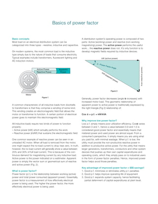
  • 1. Basic concepts Most load on an electrical distribution system can be categorized into three types - resistive, inductive and capacitive. On modern systems, the most common load is the inductive type simply due to the nature of loads that consume electricity. Typical examples include transformers, fluorescent lighting and AC induction motors. A common characteristic of all inductive loads from doorbells to transformers is that they comprise a winding of some kind. This winding creates an electromagnetic field that allows the motor or transformer to function. A certain portion of electrical power goes to maintain this electromagnetic field. All inductive loads require two kinds of power to function properly: – Active power (kW) which actually performs the work – Reactive power (kVAR) that sustains the electromagnetic field One common example of reactive power can be seen in an unloaded AC motor. When all load is removed from the motor, one might expect the no-load current to drop near zero. In truth, however, the no-load current will generally show a value between 25% and 30% of full load current. This is because of the con- tinuous demand for magnetizing current by any inductive load. Active power is the power indicated on a wattmeter. Apparent power is simply the vector sum or geometrical sum of reactive and active power (Fig. 2). What is power factor? Power factor (p.f.) is the relationship between working (active) power and total power consumed (apparent power). Essentially, power factor is a measurement of how effectively electrical power is being used. The higher the power factor, the more effectively electrical power is being used. A distribution system’s operating power is composed of two parts: Active (working) power and reactive (non-working magnetizing) power. The active power performs the useful work... the reactive power does not. It’s only function is to develop magnetic fields required by inductive devices. Generally, power factor decreases (angle Φ increases) with increased motor load. This geometric relationship of apparent power to active power is traditionally expressed by the right triangle (Fig 2) relationship of: Cos Φ = p.f. = kW/kVA Why improve low power factor? Low p.f. simply means poor utilization efficiency. CosΦ varies between 0 and 1, hence a value between 0.9 and 1.0 is considered good power factor and essentially means that metered power and used power are almost equal. From a consumer’s perspective, it simply means you are using what you paid for, with minimal wastage. When p.f. is low, the utility must provide the non-productive reactive power in addition to productive active power. For the utility that means larger generators, transformers, conductors and other system devices that pushes up their own capital expenditures and operating costs, which they simply pass on to industrial users in the form of power factor penalties. Hence, improved power factor helps avoid those penalties. Key advantage of improved power factor = $$$ savings!! 1. Good p.f. minimizes or eliminates utility p.f. penalties 2. Good p.f. helps improve operating life of equipment 3. Good p.f. expands system capacity, hence facilitating partial deferrment of capital expenditures at plant level. Basics of power factor kW (active power) kVA (apparent power) kvar(reactivepower) Active Power Reactive Power Apparent Power Motor Figure 1 Figure 2
  • 2. Basics of power factor Figure 3 illustrates the relationship of power factor to total current consumed. With a p.f. = 1.0 given a constant load, the 100% figure represents the required useful current. As the power factor drops from 1.0 to 0.9, power is used less effectively. Therefore, 10% more current is required to handle the same load. A power factor of 0.7 requires approximately 43% more current; and a power factor of 0.5 requires approxi- mately 200% (twice as much!!) current to handle the same load. How capacitors solve the problem of low p.f. Low p.f. is a problem that can be solved by adding power factor improvement (PFI) capacitors to the plant distribution system. As illustrated in Fig. 4, capacitors work as reactive current generators “supplying” reactive power (kVAR) to the system. By generating their own reactive power, industrial users free the utility from having to supply it; therefore, the total apparent power (kVA) supplied by the utility will be less, which is immediately reflected in proportionately smaller bills. Capacitors also reduce the total current drawn from the distribution system and subsequently increase system capacity. Capacitor rating Power factor correction capacitors are rated in electrical units called “vars”. One VAR = one Volt Ampere of Reactive power. VARs are units of measurement for indicating how much reactive power the capacitor will supply. As reactive power is usually measured in thousands of vars, the prefix “k” (for “kilo”) is added to create the more familiar “kVAR” term. The capacitor kVAR rating shows how much reactive power the capacitor will supply. Each unit of kVAR supplied will decrease the inductive reactive power demand by the same amount. Example (Fig. 5): A low voltage network requires 410 kW active power at full load, and the power factor is measured to be 0.70. Therefore, the system’s full load consumption of apparent power is 579.5 kVA. If 300 kVAR of capacitive reactive power is installed, the power factor will rise to 0.96 and the kVA demand will be reduced from 579.5 to 424.3 kVA. Thus, savings can vary from 20~30% or even more in some cases, which cumulatively translates to considerable money savings with the PFI equipment often paying for itself in as little as 6 months. Capacitor Utility Utility Motor WITHOUT CAPACITORS WITH CAPACITORS Reactive Power Active Power Available Active Power Motor Motor Motor 200 150 100 %Current 1 0.9 0.8 0.7 0.6 0.5 Power Factor cos-phi Fig. 3 Fig. 4 Fig. 5 Engr. MD. Arafat Rahman B.Sc. in EEE Contact: 01743340737
  • 3. Low voltage capacitor construction Options and solutions Options for improving power factor The three main options for PFI are as follows: – Individual capacitor units – One capacitor unit for each inductive load (in most cases a motor) – Banks of capacitor units – Several capacitors grouped in an enclosure that is connected at a central point in the distribution system. Fixed capacitor banks comprise multiple capacitors racked in a common enclosure with no switching while automatic capacitor banks, also called “cap banks” have capacitors in a common enclosure with contactor or thyristor (SCR) switched by a controller. – Combination of above – Where individual capacitors are installed on the larger inductive loads and banks are installed on main feeders or switchboards, etc. Advantages of individual capacitors – Increased system capacity – When active power compensation is closest to the load, it opens up system capacity and also minimizes line losses. – Cooler operation – Voltage drops cause the current to increase, thereby cumulative heat losses occur due to marginally higher current flow. When voltage drops are corrected/addressed closest to the load itself, such temperature issues are prevented right from the start. – Simpler control – Motor and capacitor can be switched ON and OFF together, which means simpler control logic and fewer control parts. – Precise compensation – Since the individual capacitor is sized to the specific load and switches together with that load, there is no chance of over compensation. – Easier selection – Selection of individual capacitors is simple and straight forward and requires no special calculations. See relevant charts on pages 11 and 13. Advantages of fixed or automatic bank systems – More economical – Cap banks are more economical than individual capacitor units when the key objective is to reduce utility power bills and/or reduce the current in primary feeders from a main generator or transformer. Being a single installation for power factor compensation simply adds to the convenience. – Lower installation costs – The cost of installing one fixed or automatic capacitor bank unit can be less than installing a number of individual capacitors next to each inductive load. – Switching – Automatic capacitor banks can switch all or part of the capacitance automatically depending on load requirements. This way, only as much power factor correction as needed for the given load is provided. (This switching capability is a primary advantage over fixed capacitor banks where over-capacitance, leading power factor and resulting overvoltages can occur should the load decrease.) – Single point of control – It is easier to manage, monitor and operate the process when the power factor inprovement (PFI) equipment is in one physical location. Combination of individual, fixed and automatic cap banks A combination of individual and centralized cap banks is often the best. Individual capacitors are installed on larger motors and banks are installed on distribution systems. To determine the total power factor correction required, then, you need to know the total kVAR requirement for the facility and the desired power factor. By referring to the Power Factor Correction Chart, (Table 2), one can calculate the capacitance needed. See selection instructions on the following pages for more details.
  • 4. Options and solutions, applications and installation Cylindrical capacitors Functionally very similar to enclosed capacitors (rectangular), cylindrical capacitors are different in terms of physical dimen- sions and arrangement of internal parts. ABB cylindrical capaci- tors, also called QCap. Cylindrical capacitors are packaged very conveniently and are best suited to plain and detuned cap banks from 100 to 300 kVAR at 480V or 600V, 60Hz, standard design for use in commercial market segments in Canada. QCap mechanical protection feature A very simple but uniquely effective design feature provides mechanical protection to each Qcap unit. The device terminals are internally connected using three notched wires that break together when the lid rises due to gas pressure. To ensure the disconnection works reliably, the wires are indirectly anchored to the lid at one end and to the can at the other. The groove is designed to support this. The lid itself is has two stable positions – normal and expanded. When pressure pushes up the lid, all three wires break and the capacitor is entirely disconnected. Logic of mechanical protection in QCap A low-impedence fault rapidly leading to a short-circuit, can be protected by a fuse. A high-impedance fault on the other hand may not lead to a current large enough to trip a fuse, it does cause cumulative resistive heating which increases the pressure in the sealed can, at a rate directly proportional to the rate of heating. Likewise, cumulative heating caused by self-healing action also slowly increases the pressure. Thereby the pressure threshold can be reached either by the long-term accumulation of gas released by self-healings (normal end of life) and/or by a high-impedance fault as described above. Capacitors special applications Care should be taken when power factor correction capacitors are used in the following applications: – Frequent starts, plugging and jogging applications – Regenerative loads where load may drive the motor (coasting, etc.) – Multi-speed motors – Motors involving open-transition reduced-voltage starting – Reversing starters that switch more than once per minute – Electronic thyristor (SCR) controlled softstarters Typical wiring diagram (detuned) Plain autobanks are exactly the same as above, only without the reactors R1, R2 and so on. SNAP on guard Rigid connections Locked by groove SNAP actuated
  • 5. Application and installation Where should power factor correction capacitors be installed in a distribution system? Fig. 6 illustrates multiple options for locating PFI capacitors on a low voltage distribution system. Option A: Downstream of the overload relay Advantages: this is the most efficient location since the reactive power (kVAR) compensation is produced right where it is consumed. Line losses and voltage drop are minimized. The capacitor is switched automatically by the motor starter, so it is only energized when the motor is running. No separate switching device or overcurrent protection required. Also, thermal overload needs to be set carefully, since the capacitor will cause a reduction in amps through the overload, hence lower trip setting for the same level of motor protection (see Table1 for line current reduction as a percent of FLA). Note: this works only with contactor starters. Special care needs to be taken in cases where softstarters are used. Option B: Between the contactor and the overload relay Advantages: same as Option A except that the overload relay can be set to the full load amps as per motor nameplate. This location is often preferred by panel builders as overload trip setting is simplified. Option C: Between the circuit breaker and the contactor Advantages: The capacitor can act as a central kVAR source for multiple motors fed by the same circuit breaker. Recommended for frequent jogging & reversing applications. Disadvantage: as the capacitor stays energized even when the motor(s) are not running, there is a risk of overcompensation and leading p.f. at light load. Also, line losses are higher than with Options A & B as the reactive current is carried further. Option D: As a central compensation source (cap bank) connected to the main distribution bus Advantages: Of the four options,this is the most cost-effective as it uses a few large kVAR capacitors rather than many small units. Also, it is a single installation, hence easier to operate, monitor and control. A power factor controller switches the capacitors in and out to ensure the correct level of compensation on the network. L3 L2 L1 Contactor T3 T2 T1 Overload Relay Fused Safety Switch or Breaker PFCC PFCCPFCC MOTOR AC B Motor Feed Fused Safety Switch or Breaker PFCC D Main Feed Fused Safety Switch or Breaker Locations for capacitors in motor circuits Fig. 6 Temperature and ventilation Low voltage capacitors should be located in adequately ventilated areas with ambient temperature below 40o C. As capacitors always operate at full load and generate heat of their own, the better the heat dissipation, the longer the operating life of the capacitor. Frequency and voltage are key factors that can cause capacitor temperature to rise. – Line frequency – variations in mains frequency can result in temperature stress in the capacitor, though modern power system frequencies tend to be increasingly stable. – Operating voltage – if operating voltage exceeds 110% of the capacitor rating, then overheating and cumulative damage can occur. In such a case, the voltage must be corrected or the capacitor must be taken offline in the shortest time possible. Note: This overvoltage problem is exactly why it is always recommended to “undersize” a capacitor’s kVAR rating during selection. Too much capacitance causes overvoltage and overvoltage in turn causes excessive heat, the cumulative effects of which can result in damage to the capacitor itself. Discharging time Low voltage capacitors need a full minute to discharge through the resistors, but it is still recommended that the terminals be short-circuited to ground after the 1-minute has elapsed and prior to human contact.