Gas Turbine
•Als PPT, PDF herunterladen•
13 gefällt mir•3,429 views

It is all about Gas Turbine and its features. Enjoy.

Empfohlen
Weitere ähnliche Inhalte
Was ist angesagt?
Was ist angesagt? (20)
Andere mochten auch
Andere mochten auch (20)
Ähnlich wie Gas Turbine
Ähnlich wie Gas Turbine (20)
Mehr von Ridwanul Hoque
Mehr von Ridwanul Hoque (20)
Kürzlich hochgeladen
Kürzlich hochgeladen (20)
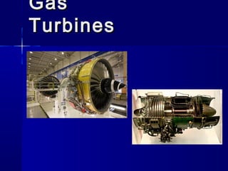
Gas Turbine
- 2. IntroductionIntroduction Gas-turbine engine:Gas-turbine engine: Any internal combustion Any internal combustion engine, employing aengine, employing a gasgas as the working fluid whichas the working fluid which is used to turn a is used to turn a turbineturbine.. The term also is conventionally used to describe aThe term also is conventionally used to describe a complete internal combustion engine consisting ofcomplete internal combustion engine consisting of at leastat least • A compressor,A compressor, • A combustion chamber, andA combustion chamber, and • A turbine. A turbine. In the gas turbine, there is a continuous flow of the working fluid.
- 3. ApplicationsApplications The outgoing gaseous fluid (exhaust) can be used to generate thrust. Useful work or propulsive thrustUseful work or propulsive thrust can be obtained from a gas-turbine engine.can be obtained from a gas-turbine engine. It may drive aIt may drive a generator, pump, or propellergenerator, pump, or propeller or, inor, in the case of a purethe case of a pure jet aircraft enginejet aircraft engine, develop thrust, develop thrust by accelerating the by accelerating the turbine exhaust flow through a exhaust flow through a nozzle (e.g. after-burner).nozzle (e.g. after-burner).
- 4. 44
- 5. 55
- 7. Working PrincipleWorking Principle This working fluid is initially compressed in the compressor. It is then heated in the combustion chamber. Finally, it goes through the turbine. The turbine converts the energy of the gas into mechanical work. Part of this work is used to drive the compressor. The remaining part is known as the net work of the gas turbine.
- 8. Cont… When examining the gas turbine cycle, we make a few assumptions. The working fluid is a perfect gas . The kinetic/potential energy of the working fluid does not vary along the gas turbine. Finally, pressure losses, mechanical losses and other kinds of losses are ignored.
- 9. Variant:Variant: Closed Brayton CycleClosed Brayton Cycle A closed Brayton cycle re-circulates the A closed Brayton cycle re-circulates the working fluidworking fluid, the air expelled from the, the air expelled from the turbine isturbine is reintroducedreintroduced into the compressor.into the compressor. This cycle uses a This cycle uses a heat exchangerheat exchanger to heat to heat the working fluid instead of an internalthe working fluid instead of an internal combustion chambercombustion chamber.. The closed Brayton cycle is used forThe closed Brayton cycle is used for example in example in closed-cycle gas turbineclosed-cycle gas turbine and and space power generation.space power generation.
- 12. The Ideal Gas Turbine Cycle (Closed Brayton Cycle) Turbine gives drive to run the compressor
- 13. Work done by Turbine per kg of air,Work done by Turbine per kg of air, WWTT = c= cpp (T(T33-T-T44)) Note: For Isentropic expansion,Note: For Isentropic expansion, Work Done = Mass (m) X Specific heat at constantWork Done = Mass (m) X Specific heat at constant Pressure (cPressure (cpp) X Change in Temperature) X Change in Temperature or,or, W= m. cW= m. cpp(T(T33-T-T44))
- 14. Work required by Compressor per kg of air,Work required by Compressor per kg of air, WW cc = c= cpp (T(T22-T-T11)) Note: For Isentropic compression,Note: For Isentropic compression, Work Done = Mass (m) X Specific heat at constantWork Done = Mass (m) X Specific heat at constant Pressure (cPressure (cpp) X Change in Temperature) X Change in Temperature or,or, W= m. cW= m. cpp(T(T22-T-T11))
- 15. Net Work available in a Gas Turbine,Net Work available in a Gas Turbine, W= WW= WT-T- WWcc or,or, WW = c= cpp (T(T33-T-T44) - c) - cpp (T(T22-T-T11)) or,or, WW = c= cpp {(T{(T33-T-T44) - (T) - (T22-T-T11)})} For Isentropic process,For Isentropic process, TTSS/T/TLL = (p= (p SS / p/ p LL)^ ()^ (γγ-1-1)/)/γγ
- 18. Basic ComponentsBasic Components CompressorCompressor – Draws in air & compresses itDraws in air & compresses it Combustion ChamberCombustion Chamber – Fuel pumped in and ignited to burn withFuel pumped in and ignited to burn with compressed aircompressed air TurbineTurbine – Hot gases converted to workHot gases converted to work – Can drive compressor & external loadCan drive compressor & external load
- 19. Basic ComponentsBasic Components CompressorCompressor – Draws in air & compresses itDraws in air & compresses it Combustion ChamberCombustion Chamber – Fuel pumped in and ignited to burn withFuel pumped in and ignited to burn with compressed aircompressed air TurbineTurbine – Hot gases converted to workHot gases converted to work – Can drive compressor & external loadCan drive compressor & external load
- 20. Basic ComponentsBasic Components CompressorCompressor – Draws in air & compresses itDraws in air & compresses it Combustion ChamberCombustion Chamber – Fuel pumped in and ignited to burn withFuel pumped in and ignited to burn with compressed aircompressed air TurbineTurbine – Hot gases converted to workHot gases converted to work – Can drive compressor & external loadCan drive compressor & external load
- 21. CompressorCompressor Supplies high pressure air forSupplies high pressure air for combustion processcombustion process Compressor typesCompressor types – Radial/centrifugal flow compressorRadial/centrifugal flow compressor – Axial flow compressorAxial flow compressor
- 22. CompressorCompressor Radial/centrifugal flowRadial/centrifugal flow – Advantages: simpleAdvantages: simple design, good for lowdesign, good for low compression ratioscompression ratios (5:1)(5:1) – Disadvantages: DifficultDisadvantages: Difficult to stage,less efficientto stage,less efficient Axial flowAxial flow – Good for highGood for high compression ratioscompression ratios (20:1)(20:1) – Most commonly usedMost commonly used
- 23. Use of Compressed AirUse of Compressed Air Primary Air (30%)Primary Air (30%) – Passes directly to combustor forPasses directly to combustor for combustion processcombustion process Secondary Air (65%)Secondary Air (65%) – Passes through holes in perforated innerPasses through holes in perforated inner shell & mixes with combustion gasesshell & mixes with combustion gases Film Cooling Air (5%)Film Cooling Air (5%) – Insulates/cools turbine bladesInsulates/cools turbine blades
- 25. Combustion ChambersCombustion Chambers Where air & fuel are mixed, ignited,Where air & fuel are mixed, ignited, and burnedand burned Spark plugs used to ignite fuelSpark plugs used to ignite fuel TypesTypes – Can: for small, centrifugal compressorsCan: for small, centrifugal compressors – Annular: for larger, axial compressorsAnnular: for larger, axial compressors (LM 2500)(LM 2500) – Can-annular: rarely usedCan-annular: rarely used
- 26. TurbinesTurbines Consists of one or more stagesConsists of one or more stages Designed to develop rotational energyDesigned to develop rotational energy Uses sets of nozzles & bladesUses sets of nozzles & blades Single shaftSingle shaft – Power coupling on same shaft as turbinePower coupling on same shaft as turbine – Same shaft drives rotor of compressorSame shaft drives rotor of compressor and power componentsand power components
- 27. TurbinesTurbines Split ShaftSplit Shaft – Gas generator turbine drives compressorGas generator turbine drives compressor – Power turbine separate from gas generator turbinePower turbine separate from gas generator turbine – Power turbine driven by exhaust from gas generatorPower turbine driven by exhaust from gas generator turbineturbine – Power turbine drives power couplingPower turbine drives power coupling
- 28. Dual Shaft, Split ShaftDual Shaft, Split Shaft
- 29. Improving Turbine EfficiencyImproving Turbine Efficiency IntercoolerIntercooler – Compressing the air in two stages andCompressing the air in two stages and using an intercooler between the two.using an intercooler between the two.
- 30. Improving Turbine EfficiencyImproving Turbine Efficiency ReheatingReheating – Expanding the air in two stages and usingExpanding the air in two stages and using a re-heater between the two.a re-heater between the two.
- 31. Other TypesOther Types Semi-Closed Cycle Gas TurbinesSemi-Closed Cycle Gas Turbines – Combination of an open and a closedCombination of an open and a closed cycle gas turbinescycle gas turbines Constant Pressure Gas TurbinesConstant Pressure Gas Turbines – Air heated in combustion chamber atAir heated in combustion chamber at constant pressureconstant pressure Constant Volume Gas TurbinesConstant Volume Gas Turbines – Air heated in combustion chamber atAir heated in combustion chamber at constant volumeconstant volume
- 32. Gas Turbine SystemsGas Turbine Systems Air SystemAir System – Air intakes are located high up & multipleAir intakes are located high up & multiple filtersfilters – Exhaust discharged out stacksExhaust discharged out stacks Fuel SystemFuel System – Uses either DFM or JP-5Uses either DFM or JP-5 Lubrication SystemLubrication System – Supply bearings and gears with oilSupply bearings and gears with oil
- 33. Advantages of gasAdvantages of gas turbine enginesturbine engines Very high power-to-weight ratioVery high power-to-weight ratio More size efficientMore size efficient Moves in one direction only, with fewerMoves in one direction only, with fewer moving partsmoving parts Low operating pressuresLow operating pressures High operation speedsHigh operation speeds Low lubricating oil cost andLow lubricating oil cost and consumptionconsumption
- 34. Disadvantages of gasDisadvantages of gas turbine enginesturbine engines More expensive compared to aMore expensive compared to a similar-sized reciprocating enginesimilar-sized reciprocating engine More complex machining operationsMore complex machining operations Usually less efficient thanUsually less efficient than reciprocating engines, especially atreciprocating engines, especially at idleidle Delayed response to changes inDelayed response to changes in power settingspower settings
- 35. ComparisonComparison Gas Turbines vs Steam TurbinesGas Turbines vs Steam Turbines Gas Turbines vs IC EnginesGas Turbines vs IC Engines Closed Cycle Gas Turbines vs OpenClosed Cycle Gas Turbines vs Open Cycle Gas TurbinesCycle Gas Turbines