Ooty Call Gril 80022//12248 Only For Sex And High Profile Best Gril Sex Avail...
Gy hm700 - final
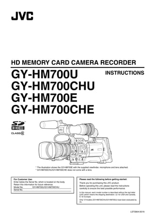
1. HD MEMORY CARD CAMERA RECORDER
GY-HM700U INSTRUCTIONS
GY-HM700CHU
GY-HM700E
GY-HM700CHE
* The illustration shows the GY-HM700E with the supplied viewfinder, microphone and lens attached.
* GY-HM700CHU/GY-HM700CHE does not come with a lens.
For Customer Use: Please read the following before getting started:
Enter below the Serial No. which is located on the body. Thank you for purchasing this JVC product.
Retain this information for future reference.
Before operating this unit, please read the instructions
Model No. GY-HM700U/GY-HM700CHU
carefully to ensure the best possible performance.
Serial No.
In this manual, each model number is described without the last letter
(U/E) which means the shipping destination. (U: for USA and Canada,
E: for Europe)
Only “U”models (GY-HM700CHU/GY-HM700U) have been evaluated by
UL.
LST0904-001A
2. Introduction
FOR USA
These are general IMPORTANT SAFEGUARDS and certain items may not apply to all appliances.
IMPORTANT SAFEGUARDS
1. Read all of these instructions.
2. Save these instructions for later use.
3. All warnings on the product and in the operating instructions should be adhered to.
4. Unplug this appliance system from the wall outlet before cleaning. Do not use liquid cleaners or aerosol
cleaners. Use a damp cloth for cleaning.
5. Do not use attachments not recommended by the appliance manufacturer as they may cause hazards.
6. Do not use this appliance near water - for example, near a bathtub, washbowl, kitchen sink, or laundry tub, in a wet
basement, or near a swimming pool, etc.
Do not place this appliance on an unstable cart, stand, or table. The appliance may fall, PORTABLE CART WARNING
7. (symbol provided by RETAC)
causing serious injury to a child or adult, and serious damage to the appliance.
Use only with a cart or stand recommended by the manufacturer, or sold with the appliance.
Wall or shelf mounting should follow the manufacturer's instructions, and should use a
mounting kit approved by the manufacturer. An appliance and cart combination should be
moved with care.
Quick stops, excessive force, and uneven surfaces may cause the appliance and cart
combination to overturn. S3125A
8. Slots and openings in the cabinet and the back or bottom are provided for ventilation, and to insure reliable operation of
the appliance and to protect it from overheating, these openings must not be blocked or covered. The openings should
never be blocked by placing the appliance on a bed, sofa, rug, or other similar surface.
This appliance should never be placed near or over a radiator or heat register.
This appliance should not be placed in a built-in installation such as a bookcase unless proper ventilation is provided.
9. This appliance should be operated only from the type of power source indicated on the marking label. If you are not sure
of the type of power supplied to your home, consult your dealer or local power company. For appliance designed to
operate from battery power, refer to the operating instructions.
10. For added protection for this product during a lightning storm, or when it is left unattended and unused for long periods
of time, unplug it form the wall outlet and disconnect the antenna or cable system. This will prevent damage to the
product due to lightning and power-line surges.
11. Do not allow anything to rest on the power cord. Do not locate this appliance where the cord will be abused by persons
walking on it.
12. Follow all warnings and instructions marked on the appliance.
13. Do not overload wall outlets and extension cords as this can result in fire or electric shock.
14. Never push objects of any kind into this appliance through cabinet slots as they may touch dangerous voltage points or
short out parts that could result in a fire or electric shock. Never spill liquid of any kind on the appliance.
15. Do not attempt to service this appliance yourself as opening or removing covers may expose you to dangerous voltage
or other hazards. Refer all servicing to qualified service personnel.
16. Unplug this appliance from the wall outlet and refer servicing to qualified service personnel under the following conditions:
a. When the power cord or plug is damaged or frayed.
b. If liquid has been spilled into the appliance.
c. If the appliance has been exposed to rain or water.
d. If the appliance does not operate normally by following the operating instructions. Adjust only those controls that
are covered by the operating instructions as improper adjustment of other controls may result in damage and will
often require extensive work by a qualified technician to restore the appliance to normal operation.
e. If the appliance has been dropped or the cabinet has been damaged.
f. When the appliance exhibits a distinct change in performance - this indicates a need for service.
17. When replacement parts are required, be sure the service technician has used replacement parts specified by the
manufacturer that have the same characteristics as the original part. Unauthorized substitutions may result in fire,
electric shock, or other hazards.
18. Upon completion of any service or repairs to this appliance, ask the service technician to perform routine safety checks
to determine that the appliance is in safe operating condition.
II
3. Safety Precautions POUR CANADA
ATTENTION
RISQUE D’ELECTROCUTION NE
PAS OUVRIR
ATT ENTION: POUR EVITER TOUT RISQUE D’ELECTROCUTION
NE PAS OUVRIR LE BOITER.
FOR USA AND CANADA AUCUNE PIECE INTERIEURE N’EST A REGLER
PAR L’UTILISATEUR.
CAUTION SE REFERER A UN AGENT QUALIFIE EN CAS DE
PROBLEME.
RISK OF ELECTRIC SHOCK
DO NOT OPEN
Le symbole de l’éclair à l’intérieur d’un triangle
équilatéral est destiné à alerter l’utilisateur sur la
CAUTION: TO REDUCE THE RISK OF ELECTRIC présence d’une “tension dangereuse” non isolée
SHOCK. DO NOT REMOVE COVER (OR
dans le boîtier du produit. Cette tension est
BACK).
NO USER-SERVICEABLE PARTSINSIDE . suffisante pour provoquer l’électrocution de
REFER SERVICING TO QUALIFIED personnes.
SERVICE PERSONNEL. Le point d’exclamation àl’intérieur d’un triangle
équilatéral est destiné à alerter l’utilisateur sur la
The lightning flash with arrowhead symbol,
présence d’opérations d’entretien importantes au
within an equilateral triangle is intended to
sujet desquelles des renseignements se trouvent
alert the user to the presence of uninsulated
dans le manuel d’instructions.
"dangerous voltage" within the product's
enclosure that may be of sufficient magnitude Ces symboles ne sont utilisésqu’aux Etats-Unis.
to constitute a risk of electric shock to
persons.
INFORMATION (FOR CANADA)
The exclamation point within an equilateral
triangle is intended to alert the user to the RENSEIGNEMENT (POUR CANADA)
presence of important operating and
maintenance (servicing) instructions in the This Class A digital apparatus complies with Canadian
literature accompanying the appliance. ICES-003.
Cet appareil numérique de la Class A est conforme à la
INFORMATION: norme NMB-003 du Canada.
This equipment has been tested and found to comply with the limits
for a Class A digital device, pursuant to Part 15 of the FCC Rules.
These limits are designed to provide reasonable protection against WARNING:
TO REDUCE THE RISK OF FIRE OR ELECTRIC
harmful interference when the equipment is operated in a
SHOCK, DO NOT EXPOSE THIS APPLIANCE TO RAIN
commercial environment.
OR MOISTURE.
This equipment generates, uses, and can radiate radio frequency
CAUTION:
energy and, if not installed and used in accordance with the
This unit should be used with 12V DC only.
instruction manual, may cause harmful interference to radio To prevent electric shocks and fire hazards, do NOT use any
communications. other power source.
Operation of this equipment in a residential area is likely to cause
harmful interference in which case the user will be required to correct NOTE:
the interference at his own expense. The rating plate (serial number plate) is on the unit.
CAUTION: REMARQUE:
CHANGES OR MODIFICAT IONS NOT APPROVED BY JVC La plaque signalétique (plaque du numéro desérie) est située sur
le cadre inférieur de l’unité.
COULD VOID USER’S AUTHORITY TO OPERATE THE
EQUIPMENT.
CAUTION:
To prevent electric shock, do not open the cabinet. No user
NOTE: serviceable parts inside. Refer servicing toqualified service
personnel.
The rating plate (serial number plate) is on this unit.
Due to design modifications, data given in this instruction book
WARNING: are subject to possible change without prior notice.
TO REDUCE THE RISK OF FIRE OR ELECTRIC SHOCK, DO NOT
EXPOSE THIS APPLIANCE TO RAIN OR MOISTURE. The apparatus shall not be exposed to dripping or splashing and
that no objects filled with liquids, such as vases, shall be placed
close to the apparatus.
AVERTISSEMENT:
THIS DEVICE COMPLIES WITH PART 15 OF THE FCC POUR EVITER LES RISQUES
RULES. D'INCENDIE OU D'ELECTROCUTION, NE PAS
OPERAT ION IS SUBJECT TO THE FOLLOWING TWO EXPOSER L'APPAREIL A L'HUMIDITE OU A LA
CONDITIONS: (1) THIS DEVICE MAY NOT CAUSE PLUIE.
HARMFUL INTERFERENCE, AND (2) THIS DEVICE MUST ATTENTION:
ACCEPT ANY INTERFERENCE RECEIVED, INCLUDING Ce magnétoscope ne doit être utili que sur du courant
sé
INTERFERENCE THAT MAY CAUSE UNDESIRED direct en 12V.
Afin d’eviter tout resque d’incendie ou d’electrocution, ne
OPERAT ION. pas utillser d’autres sources d’alimentation électrique
.
III
4. Introduction
Safety Precautions Information for Users on Disposal of Old Equipment
[European Union]
(continued)
FOR EUROPE
This equipment is in conformity with the provisions and
protection requirements of the corresponding European Attention:
Directives. This equipment is designed for professional video This symbol isonly valid in the European
appliances and can be used in the following environments: Union.
● Controlled EMC environment (for example, purpose-built
broad-casting or recording studio), and rural outdoors This symbol indicates that the electrical and electronic
environments. equipment should not be disposed as general household
waste at its end-of-life. Instead, the product should be handed
In order to keep the best performance and furthermore for over to the applicable collection point for the recycling of
electromagnetic compatibility we recommend to use cables electrical and electronic equipment for proper treatment,
not exceeding the following lengths: recovery and recycling in accordance with your national
legislation.
Port Cable Length By disposing of this product correctly, you will help to conserve
[DC INPUT] Exclusive Cable 5m natural resources and will help prevent potential negative
effects on the environment and human health which could
[Y/VIDEO], [PB], [PR] Coaxial Cable 10 m otherwise be caused by inappropriate waste handling of this
[AUDIO INPUT 1/2] Shielded Cable 3m product. For more information about collection point and
recycling of this product, please contact your local municipal
[AUDIO OUTPUT] Shielded Cable 10 m office, your household waste disposal service or the shop
[PHONES] Exclusive Cable 3m where you purchased the product. Penalties may be applicable
for incorrect disposal of this waste, in accordance with national
[IEEE1394] (HD/DV) Exclusive Cable 3m
legislation.
[HD/SD-SDI] Coaxial Cable 10 m
[REMOTE] Exclusive Cable 5m (Business users)
If you wish to dispose of this product, please visit our web
[LENS] Unshielded Cable 0.1m page http://www.jvc.eu to obtain information about the take-
[VF] Special Cable 0.3m back of the product.
[USB] Shielded Cable 3m [Other Countries outside the European Union]
If you wish to dispose of this product, please do so in
accordance with applicable national legislation or other rules
Caution: in your country for the treatment of old electrical and
Where there are strong electromagnetic waves or magnetism, for
electronic equipment.
example near a radio or TV transmitter, transformer, motor, etc.,
the picture and the sound may be disturbed. In such case, please
keep the apparatus away from the sources of the disturbance.
Dear Customer,
This apparatus is in conformance with the valid European directives and
standards regarding electromagnetic compatibility and electrical safety.
European representative of Victor Company of Japan, Limited is:
JVC Technical Services Europe GmbH
Postfach 10 05 04
61145 Friedberg
Germany
Sehr geehrter Kunde, sehr geehrte Kundin,
dieses Gerät stimmt mit den gültigen europäischen Richtlinien und
Normen bezüglich elektromagnetischer Verträglichkeit und
elektrischer Sicherheit überein.
Die europäische Vertretung für die Victor Company of Japan,
Limited ist:
JVC Technical Services Europe GmbH
Postfach 10 05 04
61145 Friedberg
Deutschland
IV
8. Introduction
Main Features New Viewfinder
With a high resolution of 852x480 in 0.425 inches, the new
viewfinder is now more robust and enables more accurate
focusing.
This camera recorder enables recording of HD format
images on an SDHC card, and also playback of these High Resolution LCD Monitor
images.
Equipped with a 4.3 inch 800x480 large LCD monitor, both
shooting precision and viewing performance are improved.
Recording in QuickTime File Format
Recording can be made in QuickTime file format of Final Cut Updated User Interface
Pro, a video editing software from Apple Inc.
The sophisticated user interface allows more intuitive
You can edit the recorded clips directly with Final Cut Pro.
operations. Thumbnail display is also available for you to
select a recorded clip for easy playback.
Recording on SDHC Memory Card (Class 6)
The absence of mechanisms with the use of SDHC (class 6) Compact Shoulder Style
as recording media brings about increased operation
By inheriting the compact shoulder style from the GY-HD100
reliability. In addition, the improved compatibility with
series which is widely accepted in the industry, more stable
computers enables high-speed data transfer to NLE as well
shooting can be done on this camera recorder while its
as reduction of operating costs.
weight remains similar to that of a handheld camera
recorder.
35 Mbps High Image Quality Mode
This camera recorder is equipped with a 35 Mbps high Lens Interchangeability
quality mode, in addition to the HDV mode bit rate (19/25
Existing lens can be used, thus saving on costs. You can
Mbps).
also select the most appropriate lens according to your
shooting requirements.
Dual Media Slots
Continuous recording is possible by loading two SDHC cards Professional Batteries
into the dual media slots, thereby allowing a long recording
Batteries such as Anton Bauer and IDX batteries that are
time.
used in the broadcast industry can be used in this camera
recorder.
Wide Variety of Recording Formats
This camera recorder supports various HD formats (1080i, Support for Wide Variety of Output
1080p, 720p) and can be used under various environments.
Supports industrial output such as HD-SDI output and
It also supports 1440x1080 and 1920x1080 full resolution in IEEE1394 output.
the 1080 format.
DV Transcode Output
Adoption of MPEG-2 Long GOP for Easy
Editing In consideration of the usage in SD environment, IEEE1394
output can also be encoded in DV format.
Shortens editing and output time by adopting MPEG-2
codec, which puts less stress on the editing computer.
Application Software Provided
High Resolution via New [Triplex Offset] The [JVC ProHD Clip Manager] application software is
provided for you to copy recorded clips to Windows or
2.5kx1.4k pixels are generated with the new Triplex Offset Macintosh computers and for checking the video images.
and a high resolution of more than 900 horizontal lines and (MP4 file format)
1000 diagonal lines is achieved using the proprietary front
processing.
The CD-ROM provided with this camera recorder
comes with [JVC ProHD Clip Manager] and other
New [Spot Meter] Function application software as well as the user guides.
The brightest and darkest positions on the screen are * For details, refer to the user guides for each application
automatically detected and displayed together with the software.
dynamic range. As this is a pre-gamma value, it allows you to
understand the lighting ratio and prevents overexposure or
underexposure in shooting scenes where lighting is
controlled.
4
9. Precautions for Proper Use Power Saving
Ⅵ When this device is not in use, be sure to set the [POWER]
switch to AOFFB in order to reduce power consumption.
Batteries
Storage and Usage Locations Ⅵ The following batteries can be used on this device.
Ⅵ Allowable ambient temperature and humidity GY-HM700CHU/GY-HM700U
: Dionic90 (Anton Bauer)
Be sure to use this device within the allowable temperature range of
0 I to 40 I and a relative humidity of 30 % to 80 %. Using this GY-HM700CHE/GY-HM700E
device at a temperature or humidity outside the allowable ranges : Endura-7 (IDX)
could result not only in malfunction but also serious impact on the * Models with an E suffix are for the European market and
CCD elements as small white spots may be generated. will not employ the UL Listing mark.
Ⅵ Strong electromagnetic waves or magnetism Ⅵ Make use of the recommended batteries. Heavy batteries
Noise may appear in the picture or audio and/or the colors may be may fall off if not used correctly.
incorrect if the camera is used near a radio or television transmitting
antenna, in places where strong magnetic fields are generated by
transformers, motors, etc., or near devices emitting radio waves, Regular Inspection (Maintenance)
such as transceivers or cellular phones.
Under normal environment, dust will accumulate on the
Ⅵ Use of wireless microphone near the camera camera recorder when it is used over a long period. Dust
When a wireless microphone or wireless microphone tuner is used may enter the camera especially if it is used outdoors. This
near the camera during recording, the tuner could pick up noise. may affect the image and sound quality of the camera
recorder. Check and replace the fan after every 9000 hours
Ⅵ Avoid using or placing this device in the following places. (suggested guideline).
● Places subject to extreme heat or cold You can check the usage time of the fan at [Others...]
● Places with excessive dirt or dust menuB[System Information]B[Fan Hour]. (A Page 88)
● Places with high humidity or moisture If the fan is used for more than 9000 hours without
replacement, AFAN MAINTENANCE REQUIREDB will be
● Places subject to smoke or vapor such as near a displayed every time you turn on the power.
cooking stove
● Places subject to strong vibrations or unstable surfaces
● In a parked car under direct sunlight or near a heater for Others
long hours
Ⅵ Do not insert objects other than the memory card into the
Ⅵ Do not place this device at places that are subject to card slot.
radiation or X-rays, or where corrosive gases occur.
Ⅵ Do not block the vent on the device.
Ⅵ Protect this device from being splashed with water. Blocking of the vent causes internal heating and may lead to
(Especially when shooting in the rain) burns and fires.
Ⅵ Protect this device from getting wet when shooting on a Ⅵ Do not turn off the [POWER] switch or remove the power
beach. In addition, salt and sand may adhere to the camera cable during recording or playback.
body. Be sure to clean the camera after use.
Ⅵ The camera may not show stable pictures for a few
Ⅵ Protect this device against penetration of dust when using seconds immediately after the power is turned on, but this is
it in a place subject to sandy dust. not a malfunction.
Ⅵ When the video signal output terminals are not in use, put
Transportation on the covers to prevent damage to the terminals.
Do not drop or hit this device against a hard object when Ⅵ Do not drop this device or subject it to strong impact or
transporting. vibration as it is a precision equipment.
Ⅵ Optical performance of lens
Due to the optical performance of the lens, color divergence
Maintenance phenomena (magnification chromatic aberration) may occur
Ⅵ Turn off the power before performing any maintenance. at the periphery of the image. This is not a camera
malfunction.
Ⅵ Wipe the external cabinet of the device with a soft cloth. Do not
wipe the body with benzene or thinner. Doing so may cause the
surface to melt or turn cloudy. When it is extremely dirty, soak the
cloth in a solution of neutral detergent, wipe the body with it, and
SDHC Cards
then use a clean cloth to remove the detergent. Use an SDHC card (4 GB to 32 GB) with Class 6 or higher
performance.
* Using cards other than those from Panasonic, TOSHIBA or
SanDisk may result in recording failure or data loss.
5
10. Introduction
Precautions for Proper Use LCD Monitor and Viewfinder
(continued) Ⅵ The LCD monitor and viewfinder screens are
manufactured using high-precision technology. Black spots
may appear on the LCD monitor and viewfinder screens, or
red, blue, and/or white spots may not turn off. However, this
is not a malfunction and these spots are not recorded on the
SDHC card.
Handling of SDHC Cards
Ⅵ If you use this device continuously for a long period of
Ⅵ The access lamp lights up in red when data on the SDHC time, the characters displayed in the viewfinder may
card is being accessed. Do not remove the SDHC card temporarily remain on the screen. This is not recorded on the
during data access (such as recording, playback, or SDHC card. They will not appear after you turn the power off
formatting). Do not turn off the power or remove the battery and then on again.
and AC adapter during access either.
Ⅵ If you use this device in a cold place, the images may
Ⅵ Do not use or store this device in a place that is subject to appear to lag on the screen, but this is not a malfunction.
static electricity or electrical noise. Retained images are not recorded on the SDHC card.
Ⅵ Do not place the SDHC card near locations that are Ⅵ Do not press against the surface with force or subject it to
exposed to strong magnetic fields or radio waves. strong impact. Doing so may damage or break the screens.
Ⅵ Inserting the SDHC card incorrectly may result in damage Ⅵ Noise may appear in the viewfinder when switching
of this device or the SDHC card. between the live video and playback images.
Ⅵ We are not liable for any accidental loss of data stored on Ⅵ Due to the characteristic of the viewfinder display device,
the SDHC card. Please back up any important data. colors may appear on the images when you blink your eyes.
This is not a malfunction. It does not affect the recorded
Ⅵ Make use of the SDHC card within the prescribed
images, SDI output, or component output.
conditions of use. Do not use the SDHC card in places.
that are subject to direct sunlight, high humidity or corrosion;
places near thermal equipment; sandy or dusty places; or in
a car under the sun with the doors and windows closed.
Characteristic CCD Phenomena
Ⅵ Smear and blooming
Ⅵ Do not bend or drop the SDHC card, or subject it to strong
impact or vibration. Due to the physical structure of CCDs, vertical streaking
(called “smear”) may occur when shooting an extremely
Ⅵ When formatting or erasing data using the camera bright light source or expansion of light (called “blooming”)
recorder, only the file administration information is changed. may appear around it. Although the CCD employed in this
The data is not completely erased from the SDHC card. If device produces very little smear or blooming, these
you want to completely erase all of the data, we recommend phenomena may still occur when shooting a bright light
either using commercially available software that is specially source.
designed for that purpose, or by physically destroying the
SDHC card with a hammer, etc. Smear
Vertical pale streaking appearing at
Ⅵ Do not dismantle or modify the SDHC card. high luminous object
Ⅵ Do not touch the terminals with your hands or with a metal High luminous object (such as light
object. bulbs, sun)
Ⅵ Do not allow dust, dirt, water, or foreign objects to adhere
to the terminals. Blooming
Monitor Screen Blurring in highlight
Ⅵ Do not remove the pasted labels or stick other labels or
stickers on the SDHC cards. Ⅵ Moire or aliasing
Ⅵ Do not use pencils or ballpoint pens to write on the SDHC Stripes, lines or other fine patterns may appear jagged when
cards. Always use oil-based pens. they are shot.
Ⅵ If you format (initialize) the SDHC card, all data recorded Ⅵ White dots
on the card, including video data and setup files, will be High temperatures can cause CCD sensor pixels to produce
deleted. white dots in the image. This is especially prominent when
Ⅵ You are recommended to use cards that are formatted boosting the sensitivity.
(initialized) on this camera recorder. This is a characteristic of the charged-coupled device (CCD).
As far as possible, use this device under conditions where
● The SDHC card may be damaged if the camera recorder is
the temperature of this device does not increase.
not operated correctly. Formatting (Initializing) the SDHC
card may allow it to operate correctly.
● SDHC cards that have been formatted (initialized) on other
cameras, computers or peripheral equipment may not
Copyright
operate correctly. In this case, format (initialize) the SDHC Any recordings made on this camera recorder that are
card on this camera recorder. played back for profit or public preview may infringe on the
rights of the owner of the recordings.
Do not use the recordings for purpose other than personal
enjoyment without prior consent from the owner.
6
11. Operation Mode
This camera recorder has three operation modes - Camera mode, Media mode, and USB mode.
The operation mode indicator on the left side of the camera recorder lights up according to the mode.
Camera Mode Media Mode
[CAM/MEDIA] Selection Button
Camera Mode IEEE1394
Mode
[CAM/MEDIA] Selection
Button
[CAM/MEDIA]
Selection SD Card Mode
Button Playback
Thumbnail Button Playback
Display (Playback/Pause/Fast Forward/
Stop Button Rewind/Clip Jump)
[CAM/MEDIA] Button
USB Connection (when the confirmation to change
to USB mode appears and [Change] is selected) Operation Mode Indicator
Connection
disabled on PC USB Mode
(USB mass storage class)
Stop Button
Playback Button
Operation
Operation Mode Mode Description
Indicator
Camera Mode Blue This is the camera shooting mode. The camera recorder starts up in Camera mode when the power is turned on.
Memo :
● Images recorded on the SDHC card cannot be played back in this mode. However, you can check (play back)
the most recently recorded image using the Clip Review function. (A Page 52)
Purple When [Rec Mode] is set to AVariable FrameB, the operation mode indicator lights up in purple during Variable
Frame REC in Camera mode. (A Page 56)
Media SD Card Green This mode allows you to play back or delete clips recorded on the SDHC card.
Mode Mode Press the [CAM/MEDIA] selection button to enter SD Card mode when you are not shooting in Camera mode.
Once the camera recorder is in SD Card mode, thumbnails of the selected media slot are displayed.
IEEE1394 Orange This is the input mode for video images from the IEEE1394-connected equipment.
Mode The camera recorder enters IEEE1394 mode when you press the [CAM/MEDIA] selection button while the power of
the equipment connected to the [IEEE1394] terminal is turned on during thumbnail display in Media mode (SD
Card mode).
Once the camera recorder is in IEEE1394 mode, the playback images of the connected equipment are displayed.
However, if the IEEE1394 connection is not recognized (such as when the power of the IEEE1394-connected
equipment is not turned on), the camera recorder will switch to Camera mode instead.
Press the [CAM/MEDIA] selection button during IEEE1394 mode to switch to Camera mode.
If the power of the equipment connected to the [IEEE1394] terminal is OFF or if connection is canceled in
IEEE1394 mode, the camera recorder will not automatically switch to other modes. To quit IEEE1394 mode, you
must operate the [CAM/MEDIA] selection button.
Note :
● This mode is used for viewing images input to the [IEEE1394] terminal from an external device, and not intended
for recording input images on the camera recorder.
USB Mode Orange This mode allows you to connect to a PC and transfer the files on an SDHC card to the PC.
When the camera recorder is connected to a USB cable, the message AChange to USB ModeB appears. Select
[Change] and press the Set button to switch to USB mode. (A Page 115)
In USB mode, the camera recorder is recognized by the connected PC as a peripheral drive (USB mass storage
class only). Disable the connection on the PC and remove the USB cable from the camera recorder to switch to
Camera mode. (A Page 115)
Memo :
● When a USB cable is connected, the message appears after recording stops.
● If playback is in progress, the message appears once the files are closed automatically, such as when playback
stops.
7
12. Introduction
Names of Parts
N ML K J
Viewfinder (A Page 11)
A
B
F G H I
Zoom Lens (A Page 14) LCD Monitor (A Page 11)
CDE Side Control Panel (A Page 10)
A Front Tally Lamp (A Page 30) (A Page 87) J Monitor Speaker (Cheek Pad) (A Page 26)
B Viewfinder Cable Clamp (A Page 20) K Shoe
C [ZEBRA ON/OFF] Zebra ON/OFF Switch (A Page 18) For mounting separately sold lights and accessories.
[SKIN AREA/SPOT METER] Skin Area/Spot Meter Switch L Microphone Holder Lock Knob (A Page 19)
(A Page 75)
M Microphone Holder (A Page 19)
D [AWB] Auto White Balance Button (A Page 40)
N Microphone (A Page 19)
E Lens Lock Lever (A Page 19)
F [MONITOR SELECT] Audio Monitor Selection Switch
(A Page 44)
G [DISPLAY] Display Button (A Page 29)
H [CAM/MEDIA] Camera/Media Mode Selection Button
(A Page 7)
I [FULL AUTO] Full Auto Shooting (FAS) Switch
(A Page 75)
8
13. a Z Y X W
W
V
O
P
Battery Mount
(A Page 21)
SDHC Slot
(A Page 13)
QR S T U
Side Terminal (A Page 12)
O Back Tally Lamp (A Page 30) (A Page 87) X [FOCUS ASSIST] Focus Assist Button
(A Page 35)
P [PHONES] Earphone Connector (3.5) (A Page 45)
Y Record Button Lock Switch
Q [LENS] Lens Connector (12-pin Connector)
(A Page 19) Set the switch toward the lens to lock the [REC] trigger
button Z.
R [INPUT1/INPUT2] Audio Input Terminal 1, 2 (XLR 3- Memo :
pin( )2ןA Page 44) ● The [REC] trigger button (A Page 10) K at the side control
panel on the right of the camera recorder is not locked.
S Microphone Cable Clamp (A Page 19)
T [CH-2 INPUT] CH-2 Audio Input Terminal Selection Z [REC] REC Trigger Button (Recording Start/Stop)
Switch Starts/stops recording.
Select the audio input terminal to record to CH-2. (A Page 44) Memo :
Memo : ● The [REC] trigger button (A Page 10) K at the side control
● Audio from [INPUT1] terminal is input to CH-1 regardless of the panel on the right of the camera recorder is interlocked with
setting. this button.
U [AUDIO INPUT 1/2] Audio Input Signal Selection a Handle
Switch (A Page 44)
V Viewfinder Connector (20-pin) (A Page 20)
W Accessory Mounting Screw Hole (x2)
9
14. Introduction
Memo :
Names of Parts (continued) ● Set the functions of the [USER1,USER2,USER3] buttons in
the menu. (A Page 74)
● When the menu screen is displayed, these buttons function
as the menu operation buttons.
( A Page 66 [Operation Buttons])
Side Control Panel E [MENU] Menu Button (A Page 66)
F [ND FILTER] ND Filter Switch (A Page 43)
A G [STATUS] Status Screen Display Button
B Press the [STATUS] button to display the Status Screen on
C P the viewfinder and LCD monitor during normal screen
display (when the menu screen is not displayed).
D ( A Page 16 [Status Screen])
O
E H [GAIN] Sensitivity Selection Switch (A Page 37)
N
F I [WHT.BAL.] White Balance Selection Switch
(A Page 40)
G M
You can select one of the three white balance types.
H
L J [POWER] Power ON/OFF Switch
I
Turns ON/OFF the power.
J K When the power is OFF, APOFFB appears on the LCD
monitor and viewfinder.
Wait for 5 seconds or more to turn on the power again.
A [VF BRIGHT] Viewfinder Luminance Adjustment Knob
(A Page 28) K [REC] REC Trigger Button (Recording Start/Stop)
Starts/stops recording.
B [VF PEAKING] Contour Adjustment Knob (A Page 28) The [REC] trigger button (A Page 9) Z on top and the [REC]
Memo : trigger button (A Page 14) of the lens are interlocked with
● This knob does not function when Focus Assist is activated. this button.
(A Page 35) Memo :
● When [1394 Rec Trigger] in the [Others] menu is set to
ASplitB, this button becomes the recording start/stop button
C [FOCUS ASSIST] Focus Assist Button of the external equipment. (A Page 88)
Press this button during shooting to display the focused area ( A Page 113 [Backup Recording])
in either blue, red, or green. This enables easy and accurate
focusing.(A Page 35)
L [CH1/CH2 AUDIO LEVEL]/[AUTO] CH-1/CH-2
D [USER1], [USER2], [USER3] User Buttons Recording Level Adjustment Knob/Auto Indicator
(A Page 74) (A Page 44)
Use these buttons to switch shooting conditions according to
the object. The functions change as below according to the M [CANCEL] Cancel Button
operation mode (A Page 7). Cancels various settings and stops playback.
During Camera Mode During Media Mode N Cross-Shaped Button (JKHI)/Set Button (R)
[USER1] ● Activates the function assigned to Adds/deletes OK
The function changes according to the operation status of
Button [USER1] in the menu. mark.
the camera recorder.
● Loads the [TC Preset] screen (A Page 64)
when pressed together with the Ⅵ During menu operation (all modes) (A Page 66)
[MENU] button. (A Page 48) Center Set button (R) : Confirms menu items and setting
[USER2] ● Activates the function assigned to Deletes clip. values
Button [USER2] in the menu. (A Page 62) Cross-shaped button (JK) : Selects menu items and setting values
● Resets settings on the [TC
Ⅵ During Camera mode
Preset]/[UB Preset] screen when
pressed. ( A Page 48, 49 ) Shutter operation :
[USER3] ● Activates the function assigned to ^ Center Set button (R) : Shutter ON/OFF
Button [USER3] in the menu. Cross-shaped button (JK) : Switches shutter speed when shutter
is ON
AE level operation: Cross-shaped button (HI)
10
15. Memo :
● When [Camera Function][Switch Set...]B[AE LEVEL] is set LCD Monitor
to AAE LEVEL/VFRB, the cross-shaped button is used to
set the number of frames during Variable Frame REC.
( A Page 56 [Variable Frame REC])
( A Page 75 [AE LEVEL])
Ⅵ During Media mode (SD Card mode) (A Page 57)
Thumbnail operation : Cross-shaped button (JKHI), center
Set button (R) A
O Operation Mode Indicator
Lights up as below according to the operation mode.
(A Page 7) When the LCD monitor is open
Operation Mode Color B
Camera Mode Blue/Purple
C
Media Mode (SD Card Mode) Green
Media Mode (IEEE1394 Mode) Orange
USB Mode Orange
Memo : D
● You can select whether to light up the indicator using [Mode
LED] in the [Others] menu. (A Page 87) E F G
P [MONITOR] Audio Monitor Level Adjustment Knob A LCD Monitor (A Page 28)
For adjusting the volume of the monitor speaker and
earphones. B [LCD PEAKING +/-] LCD Contour Adjustment Button
(A Page 28)
C [LCD BRIGHT +/-] LCD Display Brightness
Viewfinder
Adjustment Button (A Page 28)
(A Page 28)
D [AUDIO SELECT CH-1/CH-2] Audio Recording Mode
Switch (A Page 44)
E [TC DISPLAY] TC/UB Display Switch (A Page 46)
A F [TC GENE.] Time Code Generator Switch (A Page 46)
G LCD Cover Lock Release Knob (A Page 28)
B
C
D E
A Viewfinder Slide Lock Ring
For loosening the ring and adjusting the position of the
viewfinder E to the left or right.
B Eyepiece Focus Ring
For adjusting the visibility.
C Viewfinder Eyepiece Lock Ring
For loosening the ring and adjusting the eyepiece position of
the viewfinder to the front or back.
D Viewfinder
E Eyepiece
Prevents external light from entering the viewfinder screen
and cameraman’s vision.
11
16. Introduction
J Shoulder Pad Slide Button
Names of Parts (continued) For adjusting the shoulder pad position. Press this button to
adjust the shoulder pad K position to the front or back.
K Shoulder Pad
L [USB] USB Terminal (A Page 115)
M [IEEE1394] IEEE1394 Terminal (4-pin)
Side Terminal For connecting digital video equipment with IEEE1394
terminal using an IEEE1394 cable (sold separately).
To enable this terminal, set the [INT/EXT] IEEE1394 terminal
switch I to [EXT].
A ( A Page 112 [IEEE1394 Connection])
( A Page 114 [Stream Transmission to a Non-linear Editing System])
B M Note :
C L ● When connecting IEEE1394 cables, check that the
connectors are facing the right direction before you insert.
D
Memo :
E ● Put on the covers when the connectors are not in use.
F
G HI J K
A [HD/SD-SDI] HD/SD-SDI Output Terminal (BNC)
(A Page 111)
B [Y/VIDEO] Y/Composite Video Signal Output Terminal
(BNC) (A Page 111)
C [PB] PB Video Signal Output Terminal (BNC)
(A Page 111)
D [PR] PR Video Signal Output Terminal (BNC)
(A Page 111)
E [REMOTE] Remote Terminal (A Page 116)
F [DC INPUT] DC Input Terminal (A Page 21)
Input terminal for DC 12 V power supply. Connects with an
AC adapter.
G [AUDIO OUTPUT] Audio Output Terminal (RCA)
Output terminal for audio signals.
● Input audio signals are output during Camera mode.
● Playback audio signals are output during Media mode.
● Audio from input audio signals is output during HD/DV signal
(IEEE1394) input.
Memo :
● Alarm tone is not output.
H [HD/DV] IEEE1394 Terminal Mode Switch
(A Page 112)
I [INT/EXT] IEEE1394 Interface Terminal Switch
(A Page 112)
For selecting a valid IEEE1394 interface terminal.
[EXT] : Enables IEEE1394 signals from the [IEEE1394]
terminal M.
[INT] : Enables the Accessory Connector B at the rear
of the camera recorder. (A Page 13)
12
17. SD Slot Rear
(A Page 31)
E D
A
A
C
A
B B
C
A Card Slot A Status Indicator A Shoulder Belt Mount (x2)
B [SLOT SELECT] Card Slot Selection Button For mounting a shoulder belt (sold separately).
For switching SDHC cards. Note :
● Be sure to use a shoulder belt with the strength to withstand
C SDHC Card Cover the weight of this camera recorder.
● If the shoulder belt is not properly attached, the camera
D Card Slot B Status Indicator
recorder may fall and cause injuries.
E [OPEN] SDHC Card Cover Open/Close Knob ● Check the instruction manual provided with the shoulder belt
before using.
B Accessory Connector (Connect to a option)
C Battery Mounting Folder (A Page 21)
The shape is different for GY-HM700CHU/GY-HM700U and
GY-HM700CHE/GY-HM700E.
* The above is the illustration for GY-HM700CHE/GY-
HM700E.
13
18. Introduction
G Zoom Servo Control Lever
Names of Parts (continued) To operate zoom servo with the zoom servo control lever, set
the [ZOOM] switch M to ASERVOB.
● Zooms into wide angle and increases the angle of view
when AWB is pressed.
● Zooms into telephoto and decreases the angle of view when
ATB is pressed.
● Zoom speed increases when the lever is pressed hard.
Zoom Lens
(Supplied with GY-HM700U/GY-HM700E only)
H Iris Mode Switch
A : Auto iris operation mode.
CANON KT14 x 4.4KRSJ
C B A M : Manual iris operation mode.
I Iris Momentary Button
Press and hold this button to change to auto iris mode when
the iris mode switch H is set at AMB.
J [I.G.] Iris Speed Adjustment Knob
If the speed is set too fast, opening/closing of the iris
becomes unstable and hunting may occur. Readjust the
W
T
RET
AM
speed in this case.
IRIS
REC
K Filter Built-In Screw
A transparent or UV filter for lens protection can be installed
inside the lens hood from the front. Filters for various effects
can also be used.
DE F G HI J ● Installable filter types
When installed on the hood : 82mmP0.75
M When installed on the lens body : 72mmP0.75
L Zoom Servo Connector
For connecting a zoom servo unit (sold separately).
M [ZOOM] Zoom Switch
SERVO : Enables zooming with the zoom servo control
MANU. SERVO
ZOOM lever G.
K L M N O MANU. : Enables zooming with the zoom lever/ring B.
N Back Focus Ring/Lock Screw
Exclusive ring for adjusting the back focus. After adjusting,
A Focus Ring secure with a lock screw.
B Zoom Lever/Ring ( A Page 27 [Adjusting Back Focus])
To operate zoom with this lever, turn the [ZOOM] switch M O [M] Macro Focus Ring (for close-ups)
and set it to AMANU.B. Turn the ring in the direction of the arrow to take closeup
C Iris Ring shots of small objects.
Normal focusing and zooming cannot be performed in macro
To operate auto iris, set the iris mode switch H to AAB.
mode.
D Lens Cable
To take macro shots
E [REC] Record Trigger Button ● Set focus ring A to infinity (•).
Starts/stops recording. ● Set zoom ring B to the maximum wide angle.
F [RET] Return Video Button ● Rotate this ring in the direction of the arrow to adjust
focus on the object.
Press this button to play back and check the latest clip,
according to the settings under [Clip Review] of [Switch Note :
Set...] in the [Camera Function] menu. (A Page 74) ● As the back focus knob is located nearby, be careful not to
( A Page 52 [Viewing Recorded Videos Immediately (Clip mistake the two knobs.
Review)]) ● Do not forget to restore the macro ring to its original position
Memo : after use. ( A Page 27 [Adjusting Back Focus])
● When [LENS RET] of [Switch Set...] in the [Camera
Function] menu is set to AFocus AssistB, this button
functions as the Focus Assist button. (A Page 74)
14
19. Basic System Diagram
Shoulder Belt
SDI Cable
BNC
Component Cable
BNC
Microphone XLR 3P Monitor
MV-P615 Composite Cable
BNC
Earphone
Focus Manual Unit Audio Cable
HZ-FM13 (FUJINON) RCA pin
HZ-FM15 (CANON)
Monitor
Microphone External Recording
IEEE1394 Cable Device
1/3 Zoom Lens 4P-6P
Th13x3.5BRMU(FUJINON)
For GY-HM700CHU/GY-HM700U
VTR
M
Anton Bauer
PL Mount 16 mm PL Mount Anton Bauer Battery Charger
Film Lens Film Lens adapter Battery
HZ-CA13U 1/3 Zoom Lens (Dionic90)
KT14x4.4KRSJ (CANON) BR-HD50U/E*
Battery Mount
(GY-HM700U/GY-HM700E only) GY-HM700CHU/GY-HM700U : Gold Mount For GY-HM700CHE/GY-HM700E* Non-linear Editing
GY-HM700CHE/GY-HM700E : V Mount System
Zoom Servo Control
HZ-ZS13B
IDX
IDX Battery Battery Charger
Standard Package
(Endura)
Mount Converter
1/2 Zoom Lens (1/2B1/3):ACM-12 XLR 4P
Tripod Base
KA-551U AC
AC Adapter
Remote Control Unit
Carrying Case RM-LP25U/RM-LP55U/
RM-P57U
Mount Converter
(2/3B1/3): ACM-17
2/3 Zoom Lens Tripod
USB Cable
SDHC Memory Card SDHC Card Reader Non-linear Editing
System
* Models with an E suffix are for the European market and will not employ the UL Listing mark.
15
20. Introduction
LCD monitor display
Displays on the LCD The display switches between the 5 screen types with every
press of the [STATUS] button. (STATUS 0B1B2B3B4B0)
Monitor and Viewfinder Press the [DISPLAY] button to switch to the enlarged status
display screen. (A Page 17)
30/24 fps
You can display the camera status, media information, zebra
pattern, and various markers in the video image on the LCD
monitor and viewfinder screens during shooting. MAX 123%
MIN 45%
Besides camera and playback images, the following SKIN AREA
S.DTL
characters are displayed on the LCD monitor and viewfinder. B -3
A<3200K>
Ⅵ Status screen (A Page 16) STBY F5.6 AE+1 9dB 1/10000
STATUS 0 Screen
Ⅵ Auto White display *(A Page 18)
Ⅵ Menu setting screen (A Page 18) 1280x720 30/24 fps 00:00:00:00
24p HQ
Ⅵ Alarm display (A Page 18)
Ⅵ Marker and safety zone indicators *(A Page 100) MAX 123%
MIN 45%
Ⅵ Zebra pattern display (A Page 18) SKIN AREA
S.DTL
A 100min B -3
* Displayed in Camera mode only B 100min ND1/16 A<3200K>
STBY 282min F5.6 AE+1 9dB 1/10000
Memo : STATUS 1 Screen
● When [Analog Out Char.]/[SDI Out Char.] in the [A/V Out]
menu is set to AOnB, the status screen and menu screen are CAMERA INFORMATION
also displayed in the video image of the video signal output
SETUP FILE SCENE
terminal. (A Page 86) [ SCENE ]
ZEBRA1 50%~100%
ZEBRA2 70%~80%
AUDIO CH1 CH2
FORMAT QuickTime
MEDIA A 125min
B123min
STBY 282min Jan 2. 2009 01:23:45AM
Viewfinder STATUS 2 Screen
SWITCH ASSIGN
[DISPLAY] FAW NONE
GAIN [ L / M / H ] 0dB / 9dB / 12dB
Button USER 1 BARS
USER 2 B.STRETCH3
USER 3 LOAD FILE
RET CLIP REVIEW
SKIN/SPOT SPOT METER
AELEVEL AE LEVEL/VFR
STBY 282min Jan 2. 2009 01:23:45AM
[STATUS]
Button STATUS 3 Screen
30/24 fps
LCD Monitor
MAX 123%
MIN 45%
Status Screen
This screen allows you to check the current settings. STBY
To display the status screen, press the [STATUS] button in STATUS 4 Screen
the normal screen.
The status display differs according to the operation mode Press [DISPLAY] Press [DISPLAY]
(4 types). ( A Page 7 [Operation Mode])
CH1
ⅥStatus Screen in Camera Mode
CH2
DF
(A Page 90) FREE
STBY 1280 x 720
Viewfinder display A min 24p HQ
B 100 min 282min
The display switches between the 5 screen types with every
press of the [STATUS] button. (STATUS 0B1B2B3B4B0)
STATUS 1 Enlarged Display Screen
(LCD monitor only)
16
21. ⅥStatus Screen (VF/LCD) During Clip ⅥStatus Screen in USB Mode
Playback in Media Mode (SD Card Mode) This screen displays the USB mode.
(A Page 96)
The display switches between the 3 screen types with every
press of the [STATUS] button. (STATUS 0B1B2B0)
Enlarged Status Display on LCD Monitor
STATUS 0 Screen You can enlarge and display only the characters of the status
screen on the LCD monitor. (Camera mode only)
CH1
CH2
DF
FREE
STBY 1280 x 720
STATUS 1 Screen A min 24p HQ
B 100 min 282min
[DISPLAY] Button
STATUS 2 Screen
ⅥStatus Screen in Media Mode (IEEE1394
Mode) (A Page 98)
The display switches between the 2 screen types with every
press of the [STATUS] button. (STATUS 0B1B0)
1 Set [LCD + VF] in the [LCD/VF] menu to AOnB.
(A Page 82).
2 Press the [DISPLAY] button while the LCD screen is
displayed.
The display switches between the same display as the
viewfinder and the enlarged display with every press of the
STATUS 0 Screen button.
Memo :
● During enlarged display of the status on the LCD monitor
1280x720
24p HQ
screen, the video image remains displayed on the
viewfinder.
282min
STATUS 1 Screen
17