SlideShare ist ein Scribd-Unternehmen logo
1 von 18
Draft tube is used to increase the pressure from
the low turbine exit pressure to the pressure of
the surrounding to which the fluid is rejected.
The draft tube is pipe of gradually
increasing area which connects the
outlet of the runner to the tail race. It is
used to discharging water from the exit
of the turbine to the tail race. This pipe
of gradually increasing area is called
Draft tube. One end of the draft tube is
connected to the outlet of the runner
while the other end is sub-merged
below the level of water in the tail race.
PURPOSES OF DRAFT TUBE
1. It permits a negative head to be established at the outlet
of the runner and thereby increase the net head on the
turbine. The turbine may be placed above the tail race
with out any loss of net head and hence turbine may be
inspected properly
2. It converts a large proportion of the kinetic
energy(V2
2/2g) rejected at the outlet of the turbine into
useful pressure energy. Without the draft tube, the
kinetic energy rejected at the outlet of the turbine will go
waste to the tail race.
Hence by using draft tube, the net head on
the turbine increases. The turbine developed
more power and also the efficiency of the
turbine increases.
If a reaction turbine is not fitted with a draft
tube, the pressure at the outlet of the runner
will be equal to atmospheric pressure. The
water from the outlet of the runner will
discharge freely into the tail race. The net
head on the turbine will be less than that of
reaction turbine fitted with a draft tube.
Also Without the draft tube, the kinetic energy
rejected at the outlet of the turbine will go
waste to the tail race.
Types of Draft Tube
 1. Conical diffuser or straight divergent tube-
This type of draft tube consists of a conical diffuser with
half angle generally less than equal to 10° to prevent flow
separation. It is usually employed for low specific speed,
vertical shaft Francis turbine. Efficiency of this type of
draft tube is 90%
2. Simple elbow type draft Tube-
It consists of an extended elbow type tube. Generally,
used when turbine has to be placed close to the tail-race.
It helps to cut down the cost of excavation and the exit
diameter should be as large as possible to recover kinetic
energy at the outlet of runner. Efficiency of this kind of
draft tube is less almost 60%
3. Elbow with varying cross section-
It is similar to the Bent Draft tube except the
bent part is of varying cross section with
rectangular outlet. The horizontal portion of
draft tube is generally inclined upwards to
prevent entry of air from the exit end
Use of draft tube in reaction turbine
 To reduce velocity/ kinetic energy of water making
exit thereby converting kinetic energy to pressure
head allowing turbine to be installed above tail pool
level.
What is the function of draft tube
Due to high KE at the exit of reaction turbine,
there would be a loss of overall reduction in KE. So
to prevent this loss, the draft tube is provided
which produces net efficiency
purpose of draft tube in hydraulic turbines
 It makes possible the installation of the turbine above
the tail race level without the loss of head
 the velocity of water at the runner outlet is very high.
By employing a draft tube of increasing cross sectional
area, the discharge takes place at a much lower velocity
and thus, a part of the kinetic energy that was going as
a waste is recovered as a gain in the pressure head, and
this increases the efficiency of the turbine.
 The draft tube prevents the splashing of water coming
out of the runner and guides the water to the tail race.
What turbine does not require draft tube?
 Draft tube is used to increase the pressure from the
low turbine exit pressure to the pressure of the
surrounding to which the fluid is rejected.
 Only reaction turbines require a draft tube as there is
low pressure at the exit of the turbine, where as in
impulse turbine the pressure at the inlet and the exit is
essentially the same, which is above the pressure to
which the fluid rejected and thus it require no draft
tube.
Consider a capital draft tube
Hs = vertical height of draft tube
above the tail race
Y = distance of bottom of draft tube
from tail race
Applying Bernoulli’s equation to inlet (1 – 1) and outlet (2 – 2)
of the draft tube and taking section 2 – 2 as the datum line
We get
(P1/ ρg) + (V1
2/2g) + (Hs + y) = (P2/ ρg) + (V2
2/2g) + 0 + hf ----------------(1)
Where hf = loss of energy between section 1-1 and 2-2
But
(P2/ ρg) = atmospheric pressure head + y
= (Pa/ ρg) + y
Substituting this value of (P2/ ρg) in equation (1), we get
This equation (P1/ρg) is less than atmospheric pressure
EFFICIENCY
Actual conversion of kinetic head into pressure head
Kinetic head at the inlet of draft tube
Efficiency =
Actual conversion of kinetic head into
pressure head =
Theoretical conversion of kinetic head
into pressure head in draft tube =
EFFICIENCY =
V1= Velocity of water at inlet of Draft tube
V2= Velocity of water at outlet of Draft tube and
hf= Loss of head in the Draft tube
AJESH
BY
R
ARAYANKARA

Weitere ähnliche Inhalte

Was ist angesagt?

PELTON WHEEL TURBINE
PELTON WHEEL TURBINEPELTON WHEEL TURBINE
PELTON WHEEL TURBINE
gyan singh
 

Was ist angesagt? (20)

Francis Turbine
Francis Turbine Francis Turbine
Francis Turbine
 
Hydraulic ram
Hydraulic ramHydraulic ram
Hydraulic ram
 
Turbine.ppt
Turbine.pptTurbine.ppt
Turbine.ppt
 
Pelton turbine
Pelton turbinePelton turbine
Pelton turbine
 
Hydraulic turbines
Hydraulic turbinesHydraulic turbines
Hydraulic turbines
 
Losses in Pipe
Losses in PipeLosses in Pipe
Losses in Pipe
 
centrifugal pump ppt
centrifugal pump pptcentrifugal pump ppt
centrifugal pump ppt
 
Impact of jet
Impact of jetImpact of jet
Impact of jet
 
Performance of-turbines
Performance of-turbinesPerformance of-turbines
Performance of-turbines
 
Hydraulics & hydraulic machinery
Hydraulics & hydraulic machineryHydraulics & hydraulic machinery
Hydraulics & hydraulic machinery
 
PPT On Hydraulic Machines - Turbines
PPT On Hydraulic Machines - TurbinesPPT On Hydraulic Machines - Turbines
PPT On Hydraulic Machines - Turbines
 
Drag force & Lift
Drag force & LiftDrag force & Lift
Drag force & Lift
 
Hydraulic turbines
Hydraulic turbinesHydraulic turbines
Hydraulic turbines
 
Pelton Wheel Turbine Part 2
Pelton Wheel Turbine Part 2Pelton Wheel Turbine Part 2
Pelton Wheel Turbine Part 2
 
Flow through pipes ppt
Flow through pipes pptFlow through pipes ppt
Flow through pipes ppt
 
Pumps
PumpsPumps
Pumps
 
Types of turbine & thier application
Types of turbine & thier applicationTypes of turbine & thier application
Types of turbine & thier application
 
Francis turbine
Francis turbine Francis turbine
Francis turbine
 
PELTON WHEEL TURBINE
PELTON WHEEL TURBINEPELTON WHEEL TURBINE
PELTON WHEEL TURBINE
 
losses in pipe flow
losses in pipe flowlosses in pipe flow
losses in pipe flow
 

Andere mochten auch

Power is transmitted through pipe_AMIT
Power is transmitted through pipe_AMITPower is transmitted through pipe_AMIT
Power is transmitted through pipe_AMIT
Amit Sharma
 
Basic Mechanical Engineering- Hydraulic turbines
Basic Mechanical Engineering- Hydraulic turbinesBasic Mechanical Engineering- Hydraulic turbines
Basic Mechanical Engineering- Hydraulic turbines
Steve M S
 
Hydraulic turbines
Hydraulic turbinesHydraulic turbines
Hydraulic turbines
Dr. Ramesh B
 
Energy Conservation Opportunities in industries at GCET
Energy Conservation Opportunities in industries at GCETEnergy Conservation Opportunities in industries at GCET
Energy Conservation Opportunities in industries at GCET
JIGNESH PATEL
 

Andere mochten auch (20)

Power is transmitted through pipe_AMIT
Power is transmitted through pipe_AMITPower is transmitted through pipe_AMIT
Power is transmitted through pipe_AMIT
 
Basic Mechanical Engineering- Hydraulic turbines
Basic Mechanical Engineering- Hydraulic turbinesBasic Mechanical Engineering- Hydraulic turbines
Basic Mechanical Engineering- Hydraulic turbines
 
Hydraulic turbines
Hydraulic turbinesHydraulic turbines
Hydraulic turbines
 
Hydraulic turbine
Hydraulic  turbineHydraulic  turbine
Hydraulic turbine
 
Ppt of turbine
Ppt of turbinePpt of turbine
Ppt of turbine
 
Hydropower
HydropowerHydropower
Hydropower
 
Governing of francis turbine
Governing of francis turbineGoverning of francis turbine
Governing of francis turbine
 
Governing of hydraulic turbines.
Governing of hydraulic turbines.Governing of hydraulic turbines.
Governing of hydraulic turbines.
 
Hydro Power Plant
Hydro Power PlantHydro Power Plant
Hydro Power Plant
 
Energy Conservation Opportunities in industries at GCET
Energy Conservation Opportunities in industries at GCETEnergy Conservation Opportunities in industries at GCET
Energy Conservation Opportunities in industries at GCET
 
Broadband Over Power Lines (BPL)
Broadband Over Power Lines (BPL)Broadband Over Power Lines (BPL)
Broadband Over Power Lines (BPL)
 
Reaction turbine
Reaction turbineReaction turbine
Reaction turbine
 
Energy efficient ventilation system
Energy efficient ventilation systemEnergy efficient ventilation system
Energy efficient ventilation system
 
Jet pump
Jet pumpJet pump
Jet pump
 
Diesel power plant
Diesel power plantDiesel power plant
Diesel power plant
 
ELECTRIC POWER GENERATION FROM TRAFFIC
ELECTRIC  POWER GENERATION  FROM TRAFFICELECTRIC  POWER GENERATION  FROM TRAFFIC
ELECTRIC POWER GENERATION FROM TRAFFIC
 
SI Units
SI UnitsSI Units
SI Units
 
Jet pump
Jet pumpJet pump
Jet pump
 
Torque converter
Torque converterTorque converter
Torque converter
 
Causes and Effects of cavitation In Hydraulic power plants
Causes and Effects of cavitation In Hydraulic power plantsCauses and Effects of cavitation In Hydraulic power plants
Causes and Effects of cavitation In Hydraulic power plants
 

Ähnlich wie Draft tube

hydraulicmachines-200422173920.pdf
hydraulicmachines-200422173920.pdfhydraulicmachines-200422173920.pdf
hydraulicmachines-200422173920.pdf
ChandreshTripathi6
 
turbine in plant
turbine in plantturbine in plant
turbine in plant
Naman Meena
 

Ähnlich wie Draft tube (20)

Draft tube
Draft tubeDraft tube
Draft tube
 
5. francis turbine
5. francis turbine5. francis turbine
5. francis turbine
 
Turbines seminar ppt
Turbines seminar pptTurbines seminar ppt
Turbines seminar ppt
 
Design and Analysis of Low Head, Light weight Kaplan Turbine Blade
Design and Analysis of Low Head, Light weight Kaplan Turbine BladeDesign and Analysis of Low Head, Light weight Kaplan Turbine Blade
Design and Analysis of Low Head, Light weight Kaplan Turbine Blade
 
centrifugal compressor.pptx
centrifugal compressor.pptxcentrifugal compressor.pptx
centrifugal compressor.pptx
 
hydraulic-machines.pptx
hydraulic-machines.pptxhydraulic-machines.pptx
hydraulic-machines.pptx
 
STEAM NOZZLE AND STEAM TURBINE
STEAM NOZZLE AND STEAM TURBINESTEAM NOZZLE AND STEAM TURBINE
STEAM NOZZLE AND STEAM TURBINE
 
Steam Turbines
Steam TurbinesSteam Turbines
Steam Turbines
 
hydraulicmachines-200422173920.pdf
hydraulicmachines-200422173920.pdfhydraulicmachines-200422173920.pdf
hydraulicmachines-200422173920.pdf
 
Hydraulic machines
Hydraulic machinesHydraulic machines
Hydraulic machines
 
Hydro electric power plant
Hydro electric power plantHydro electric power plant
Hydro electric power plant
 
Turbomachinery Turbine pump Compressor.ppt
Turbomachinery Turbine pump Compressor.pptTurbomachinery Turbine pump Compressor.ppt
Turbomachinery Turbine pump Compressor.ppt
 
turbine in plant
turbine in plantturbine in plant
turbine in plant
 
Steam turbine
Steam turbineSteam turbine
Steam turbine
 
UNIT-III_Steam_Turbine (1).pdf
UNIT-III_Steam_Turbine (1).pdfUNIT-III_Steam_Turbine (1).pdf
UNIT-III_Steam_Turbine (1).pdf
 
Turbine.pptx
Turbine.pptxTurbine.pptx
Turbine.pptx
 
Pompa.pptx
Pompa.pptxPompa.pptx
Pompa.pptx
 
Steam Turbine_edit.pptx
Steam Turbine_edit.pptxSteam Turbine_edit.pptx
Steam Turbine_edit.pptx
 
Pelton turbine
Pelton turbinePelton turbine
Pelton turbine
 
Francis's turbine
Francis's turbine Francis's turbine
Francis's turbine
 

Kürzlich hochgeladen

"Lesotho Leaps Forward: A Chronicle of Transformative Developments"
"Lesotho Leaps Forward: A Chronicle of Transformative Developments""Lesotho Leaps Forward: A Chronicle of Transformative Developments"
"Lesotho Leaps Forward: A Chronicle of Transformative Developments"
mphochane1998
 
Hospital management system project report.pdf
Hospital management system project report.pdfHospital management system project report.pdf
Hospital management system project report.pdf
Kamal Acharya
 

Kürzlich hochgeladen (20)

School management system project Report.pdf
School management system project Report.pdfSchool management system project Report.pdf
School management system project Report.pdf
 
Employee leave management system project.
Employee leave management system project.Employee leave management system project.
Employee leave management system project.
 
Thermal Engineering -unit - III & IV.ppt
Thermal Engineering -unit - III & IV.pptThermal Engineering -unit - III & IV.ppt
Thermal Engineering -unit - III & IV.ppt
 
DC MACHINE-Motoring and generation, Armature circuit equation
DC MACHINE-Motoring and generation, Armature circuit equationDC MACHINE-Motoring and generation, Armature circuit equation
DC MACHINE-Motoring and generation, Armature circuit equation
 
Tamil Call Girls Bhayandar WhatsApp +91-9930687706, Best Service
Tamil Call Girls Bhayandar WhatsApp +91-9930687706, Best ServiceTamil Call Girls Bhayandar WhatsApp +91-9930687706, Best Service
Tamil Call Girls Bhayandar WhatsApp +91-9930687706, Best Service
 
NO1 Top No1 Amil Baba In Azad Kashmir, Kashmir Black Magic Specialist Expert ...
NO1 Top No1 Amil Baba In Azad Kashmir, Kashmir Black Magic Specialist Expert ...NO1 Top No1 Amil Baba In Azad Kashmir, Kashmir Black Magic Specialist Expert ...
NO1 Top No1 Amil Baba In Azad Kashmir, Kashmir Black Magic Specialist Expert ...
 
Double Revolving field theory-how the rotor develops torque
Double Revolving field theory-how the rotor develops torqueDouble Revolving field theory-how the rotor develops torque
Double Revolving field theory-how the rotor develops torque
 
Learn the concepts of Thermodynamics on Magic Marks
Learn the concepts of Thermodynamics on Magic MarksLearn the concepts of Thermodynamics on Magic Marks
Learn the concepts of Thermodynamics on Magic Marks
 
Generative AI or GenAI technology based PPT
Generative AI or GenAI technology based PPTGenerative AI or GenAI technology based PPT
Generative AI or GenAI technology based PPT
 
"Lesotho Leaps Forward: A Chronicle of Transformative Developments"
"Lesotho Leaps Forward: A Chronicle of Transformative Developments""Lesotho Leaps Forward: A Chronicle of Transformative Developments"
"Lesotho Leaps Forward: A Chronicle of Transformative Developments"
 
HAND TOOLS USED AT ELECTRONICS WORK PRESENTED BY KOUSTAV SARKAR
HAND TOOLS USED AT ELECTRONICS WORK PRESENTED BY KOUSTAV SARKARHAND TOOLS USED AT ELECTRONICS WORK PRESENTED BY KOUSTAV SARKAR
HAND TOOLS USED AT ELECTRONICS WORK PRESENTED BY KOUSTAV SARKAR
 
457503602-5-Gas-Well-Testing-and-Analysis-pptx.pptx
457503602-5-Gas-Well-Testing-and-Analysis-pptx.pptx457503602-5-Gas-Well-Testing-and-Analysis-pptx.pptx
457503602-5-Gas-Well-Testing-and-Analysis-pptx.pptx
 
S1S2 B.Arch MGU - HOA1&2 Module 3 -Temple Architecture of Kerala.pptx
S1S2 B.Arch MGU - HOA1&2 Module 3 -Temple Architecture of Kerala.pptxS1S2 B.Arch MGU - HOA1&2 Module 3 -Temple Architecture of Kerala.pptx
S1S2 B.Arch MGU - HOA1&2 Module 3 -Temple Architecture of Kerala.pptx
 
AIRCANVAS[1].pdf mini project for btech students
AIRCANVAS[1].pdf mini project for btech studentsAIRCANVAS[1].pdf mini project for btech students
AIRCANVAS[1].pdf mini project for btech students
 
Introduction to Data Visualization,Matplotlib.pdf
Introduction to Data Visualization,Matplotlib.pdfIntroduction to Data Visualization,Matplotlib.pdf
Introduction to Data Visualization,Matplotlib.pdf
 
Introduction to Serverless with AWS Lambda
Introduction to Serverless with AWS LambdaIntroduction to Serverless with AWS Lambda
Introduction to Serverless with AWS Lambda
 
Hospital management system project report.pdf
Hospital management system project report.pdfHospital management system project report.pdf
Hospital management system project report.pdf
 
Thermal Engineering-R & A / C - unit - V
Thermal Engineering-R & A / C - unit - VThermal Engineering-R & A / C - unit - V
Thermal Engineering-R & A / C - unit - V
 
Hostel management system project report..pdf
Hostel management system project report..pdfHostel management system project report..pdf
Hostel management system project report..pdf
 
COST-EFFETIVE and Energy Efficient BUILDINGS ptx
COST-EFFETIVE  and Energy Efficient BUILDINGS ptxCOST-EFFETIVE  and Energy Efficient BUILDINGS ptx
COST-EFFETIVE and Energy Efficient BUILDINGS ptx
 

Draft tube

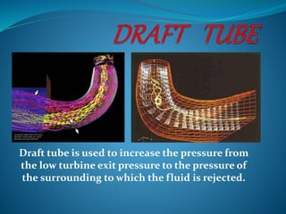
  • 1. Draft tube is used to increase the pressure from the low turbine exit pressure to the pressure of the surrounding to which the fluid is rejected.
  • 2. The draft tube is pipe of gradually increasing area which connects the outlet of the runner to the tail race. It is used to discharging water from the exit of the turbine to the tail race. This pipe of gradually increasing area is called Draft tube. One end of the draft tube is connected to the outlet of the runner while the other end is sub-merged below the level of water in the tail race.
  • 3. PURPOSES OF DRAFT TUBE 1. It permits a negative head to be established at the outlet of the runner and thereby increase the net head on the turbine. The turbine may be placed above the tail race with out any loss of net head and hence turbine may be inspected properly 2. It converts a large proportion of the kinetic energy(V2 2/2g) rejected at the outlet of the turbine into useful pressure energy. Without the draft tube, the kinetic energy rejected at the outlet of the turbine will go waste to the tail race.
  • 4. Hence by using draft tube, the net head on the turbine increases. The turbine developed more power and also the efficiency of the turbine increases. If a reaction turbine is not fitted with a draft tube, the pressure at the outlet of the runner will be equal to atmospheric pressure. The water from the outlet of the runner will discharge freely into the tail race. The net head on the turbine will be less than that of reaction turbine fitted with a draft tube. Also Without the draft tube, the kinetic energy rejected at the outlet of the turbine will go waste to the tail race.
  • 6.  1. Conical diffuser or straight divergent tube- This type of draft tube consists of a conical diffuser with half angle generally less than equal to 10° to prevent flow separation. It is usually employed for low specific speed, vertical shaft Francis turbine. Efficiency of this type of draft tube is 90%
  • 7. 2. Simple elbow type draft Tube- It consists of an extended elbow type tube. Generally, used when turbine has to be placed close to the tail-race. It helps to cut down the cost of excavation and the exit diameter should be as large as possible to recover kinetic energy at the outlet of runner. Efficiency of this kind of draft tube is less almost 60%
  • 8. 3. Elbow with varying cross section- It is similar to the Bent Draft tube except the bent part is of varying cross section with rectangular outlet. The horizontal portion of draft tube is generally inclined upwards to prevent entry of air from the exit end
  • 9. Use of draft tube in reaction turbine  To reduce velocity/ kinetic energy of water making exit thereby converting kinetic energy to pressure head allowing turbine to be installed above tail pool level. What is the function of draft tube Due to high KE at the exit of reaction turbine, there would be a loss of overall reduction in KE. So to prevent this loss, the draft tube is provided which produces net efficiency
  • 10. purpose of draft tube in hydraulic turbines  It makes possible the installation of the turbine above the tail race level without the loss of head  the velocity of water at the runner outlet is very high. By employing a draft tube of increasing cross sectional area, the discharge takes place at a much lower velocity and thus, a part of the kinetic energy that was going as a waste is recovered as a gain in the pressure head, and this increases the efficiency of the turbine.  The draft tube prevents the splashing of water coming out of the runner and guides the water to the tail race.
  • 11. What turbine does not require draft tube?  Draft tube is used to increase the pressure from the low turbine exit pressure to the pressure of the surrounding to which the fluid is rejected.  Only reaction turbines require a draft tube as there is low pressure at the exit of the turbine, where as in impulse turbine the pressure at the inlet and the exit is essentially the same, which is above the pressure to which the fluid rejected and thus it require no draft tube.
  • 12. Consider a capital draft tube Hs = vertical height of draft tube above the tail race Y = distance of bottom of draft tube from tail race
  • 13. Applying Bernoulli’s equation to inlet (1 – 1) and outlet (2 – 2) of the draft tube and taking section 2 – 2 as the datum line We get (P1/ ρg) + (V1 2/2g) + (Hs + y) = (P2/ ρg) + (V2 2/2g) + 0 + hf ----------------(1) Where hf = loss of energy between section 1-1 and 2-2 But (P2/ ρg) = atmospheric pressure head + y = (Pa/ ρg) + y
  • 14. Substituting this value of (P2/ ρg) in equation (1), we get This equation (P1/ρg) is less than atmospheric pressure
  • 16. Actual conversion of kinetic head into pressure head Kinetic head at the inlet of draft tube Efficiency = Actual conversion of kinetic head into pressure head = Theoretical conversion of kinetic head into pressure head in draft tube =
  • 17. EFFICIENCY = V1= Velocity of water at inlet of Draft tube V2= Velocity of water at outlet of Draft tube and hf= Loss of head in the Draft tube