Ntpc vocational training project report sipat
•Als DOC, PDF herunterladen•
18 gefällt mir•13,993 views

Ntpc vocational training project report sipat

Empfohlen
Empfohlen
Weitere ähnliche Inhalte
Was ist angesagt?
Was ist angesagt? (20)
Andere mochten auch
Andere mochten auch (19)
Ähnlich wie Ntpc vocational training project report sipat
Ähnlich wie Ntpc vocational training project report sipat (20)
Mehr von pratikguptateddy
Kürzlich hochgeladen
Kürzlich hochgeladen (20)
Ntpc vocational training project report sipat
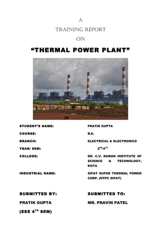
- 1. A TRAINING REPORT ON “THERMAL POWER PLANT” STUDENT’S NAME: PRATIK GUPTA COURSE: B.E. BRANCH: ELECTRICAL & ELECTRONICS 2ND/4TH YEAR/ SEM: COLLEGE: DR. C.V. RAMAN INSTITUTE OF SCIENCE & TECHNOLOGY, KOTA INDUSTRIAL NAME: SIPAT SUPER THERMAL POWER CORP. (NTPC SIPAT) SUBMITTED BY: SUBMITTED TO: PRATIK GUPTA MR. PRAVIN PATEL (EEE 4 TH SEM)
- 2. CERTIFICATE This is to certify that the project report entitled as NATIONAL THERMAL POWER PLANT has been done by PRATIK GUPTA during his vocational training period from 20-06-13 to 20-07-13 at “SIPAT SUPER THERMAL POWER PROJECT” is a record of studies, site experience and keen interest to the subject and analysis carried out by him under my supervision and guidance. This is a part of partial fulfilment of their vocational training programme. Guided by:1. MR. SHALABH SAHRMA 2. MR. J.P.Patel 3. MR. Dilip Khalatkar 4. MR. P.K. DAS
- 3. DECLARATION The training work has been carried out and the report prepared by me during 20th June to 20th July 2013 under the guidance of faculties ntpc ltd/sipat thermal power plant and organised by employ development centre, human resource development. This is the original work carried out by me and not has been taken from any other sources nor been submitted to any institute or organisation as a fulfilment of any other curriculum.
- 4. ACKNOWLEDGEMENT I hereby convey my deep and sincere gratitude in all humbleness to respected 5. MR. SHALABH SAHRMA 6. MR. J.P.Patel 7. MR. Dilip Khalatkar 8. MR. P.K. DAS Who provided me with an opportunity to learn under their gracious guidance, meticulous care and throughout the training. Their personal supervision and guidance has enabled me to complete this Project. I also thankfully acknowledgement the assistance received from MR PRAVIN PATEL and others for their co-operation during the preparation of this project report. The project report would not have been shaped in this form without their encouragement and guidance.
- 5. Contents 1. Introduction of NTPC 2. Introduction about Project 3. Production of Electricity 4. Principal of Steam Power Plant 5. Coal Handling Plant 6. Coal Handling Plant Power Distribution 7. Demineral Plant(DM Plant) 8. Coal ,Water and Steam Cycle 9. H.T. Switch gear 10. L.T. Switch gear 11. Generators and Transformers 12. D.C. System 13. Switch Yard 14. Conclusion
- 6. INTRODUCTION OF NTPC India’s largest power company, NTPC was set up in 1975 to accelerate power development in India. NTPC is emerging as a diversified power major with presence in the entire value chain of the power generation business. Apart from power generation, which is the mainstay of the company, NTPC has already ventured into consultancy, power trading, ash utilization and coal mining. NTPC ranked 337th in the ‘2012, Forbes Global 2000’ ranking of the World’s biggest companies. NTPC became a Maharatna company in May, 2010, one of the only four companies to be awarded this status. The total installed capacity of the company is 41,184 MW (including JVs) with 16 coal based and 7 gas based stations, located across the country. In addition under JVs, 7 stations are coal based & another station uses naptha/LNG as fuel and 2 renewable energy projects. The company has set a target to have an installed power generating capacity of 1,28,000 MW by the year 2032. The capacity will have a diversified fuel mix comprising 56% coal, 16% Gas, 11% Nuclear and 17% Renewable Energy Sources(RES) including hydro. By 2032, non fossil fuel based generation capacity shall make up nearly 28% of NTPC’s portfolio. NTPC has been operating its plants at high efficiency levels. Although the company has 17.75% of the total national capacity, it contributes 27.40% of total power generation due to its focus on high efficiency. In October 2004, NTPC launched its Initial Public Offering (IPO) consisting of 5.25% as fresh issue and 5.25% as offer for sale by Government of India. NTPC thus became a listed company in November 2004 with the Government holding 89.5% of the equity share capital. In February 2010, the Shareholding of Government of India was reduced from 89.5% to 84.5% through Further Public Offer. The rest is held by Institutional Investors and the Public.
- 7. At NTPC, People before Plant Load Factor is the mantra that guides all HR related policies. NTPC has been awarded No.1, Best Workplace in India among large organizations and the best PSU for the year 2010, by the Great Places to Work Institute, India Chapter in collaboration with The Economic Times. The concept of Corporate Social Responsibility is deeply ingrained in NTPC's culture. Through its expansive CSR initiatives, NTPC strives to develop mutual trust with the communities that surround its power stations.
- 8. INTRODUCTION ABOUT PROJECT Sipat Super Thermal Power Station is located at Sipat in Bilaspur district in state of Chhattisgarh. The power plant is one of the coal based power plants of NTPC. The coal for the power plant is sourced from Dipika Mines of South Eastern Coalfields Limited. The project has an installed capacity of 2980 MW consisting of two stages, stage one which got commissioned late was of 3 units of 660 MW each involving super-critical boilers technology and stage two consisted of 2 units of 500 MW each. Stage Unit Number Installed Capacity (MW) Date of Commissioning Status 1st 1 660 2011 June Running 1st 2 660 2011 December Running 1st 3 660 2012 June [1] Running 2nd 4 500 2007 May Running 2nd 5 500 2008 August Running Total Five 2980 Sipat Sipat' is a small developing town, approximately 22 kilometers away from Bilaspur, Chhattisgarh, the second largest city in Chhattisgarh. It has been in news due to setup of new power plant by NTPC Limited in that area. The project was started on 2001 by Indian former Prime Minister Mr. Atal Bihari Vajpayee.NTPC Sipat has total installed capacity of 2980 MW.NTPC Sipat has two stages: Stage-I comprises 3 units of 660MW each and Stage-II comprises 2 units of 500MW each. The thermal power generation in NTPC sipat Stage-II is based on "Super Critical Boiler Technology" which is the advanced technology in thermal power generation. NTPC Limited has helped this town in developing by providing business prospective in that area and by providing education, healthcare facilities.
- 9. PRODUCTION OF ELECTRICITY The means and steps involved in the production of electricity in a coal-fired power station are described below. The coal, brought to the station by train or other means, travels from the coal handling plant by conveyer belt to the coal bunkers, from where it is fed to the pulverizing mills which grinds it as fine as face powder. The finely powdered coal mixed with pre-heated air is then blown into the boiler by fan called Primary Air Fan where it burns, more like a gas than as a solid in convectional domestic or industrial grate, with additional amount of air called secondary air supplied by Forced Draft Fan. As the coal has been grounded so finely the resultant ash is also a fine powder. Some of this ash binds together to form lumps which fall into the ash pits at the bottom of the furnace. The water quenched ash from the bottom of the furnace is conveyed to pits for subsequent disposal or sale. Most of ash, still in fine particles form is carried out of the boiler to the precipitators as dust, where it is trapped by electrodes charged with high voltage electricity. The dust is then conveyed by water to disposal areas or to bunkers for sale while the cleaned flue gases pass on through ID Fan to be discharged up the chimney. Meanwhile the heat released from the coal has been absorbed by the many kilometres of tubing which line the boiler walls. Inside the tubes is the boiler feed water which is transformed by the heat into the steam at high pressure and temperature. The steam super-heated in further tubes (Super Heater) passes to the turbine where it is discharged through the nozzles on the turbine blades. Just the energy of the wind turns the sail of the wind-mill, so the energy of the steam, striking the blades, makes the turbine rotate. Coupled to the end of the turbine is the rotor of the generator – a large cylindrical magnet, so that when the turbine rotates the rotor turns with it. The rotor is housed inside the stator having heavy coils of copper bars in which electricity is produced through the movement of the magnetic field created by the rotor. The electricity passes from the stator winding to the step-up transformer which increases its voltage so that it can be transmitted efficiently over the power lines of the grid.
- 10. The steam which has given up its heat energy is changed back into water in the condenser so that it is ready for re-use. The condenser contains many kilometres of tubing through which the colder is constantly pumped. The steam passing around the tubes looses the heat and is rapidly changed back to water. But the two lots of water (i.e. boiler feed water & cooling water) must NEVER MIX. The cooling water is drawn from the river, but the boiler feed water must be absolutely pure, far purer than the water we drink, if it is not to damage the boiler tubes. Chemistry at the power station is largely the chemistry of water. To condense the large quantities of steam, huge and continuous volume of cooling water is essential. In most of the power stations the same water is to be used over and over again. So the heat which the water extracts from the steam in the condenser is removed by pumping the water out to the cooling towers. The cooling towers are simply concrete shells acting as huge chimneys creating a draught (natural/mechanically assisted by fans) of air. The water is sprayed out at the top of towers and as it falls into the pond beneath it is cooled by the upward draught of air. The cold water in the pond is then circulated by pumps to the condensers. Inevitably, however, some of the water is drawn upwards as vapours by the draught and it is this which forms the familiar white clouds which emerge from the towers seen sometimes. Why bother to change steam from the turbine back into water if it has to be heated up again immediately? The answer lies in the law of physics which states that the boiling point of water is related to pressure. The lower the pressure, the lower the temperature at which water boils. The turbine designer want as low boiling point of water as possible because he can only utilize the energy of the steam – when the steam changes back into water he can get NO more work out of it. So a condenser is built, which by rapidly changing the steam back into water creates a vacuum. This vacuum results in a much lower boiling point which, in turns, means he can continue getting work out of the steam well below 100 degree Celsius at which it would normally change into water.
- 11. Principle of the Steam Power Plant The working principle of a steam plant is based upon the Rankine cycle. Generally steam is taken as the working medium due to its ability to be stable and that it’s readily stable. The flow of steam in the plant can be very easily be understood by the flow diagram of the plant. A graph plotted between the temperature and the entropy would indicate the technical details of the working by the rankine cycle. The entropy of a system can be understood as an index of degradation of energy. PLANT FLOW DIAGRAM COAL HANDLING PLANT Introduction: NTPC SIPAT gets its coal supply mainly from dipka mines. The coal being filled in the wagons of the rail reaches plant. The purpose of this plant is to convey the coal to the bunker in the size not larger than 20mm.It handles and transports the coal to the bunker from the wagons by passing through various conveyors, transfer points, crusher houses, etc. Type of unloading the coal: 1. Manual Unloading: -Previously, manpower was used for unloading the wagons. But it was very time consuming and more workers were required for the job to be done.
- 12. 2. Box in (using wagon tippler for unloading): -For this method, Indian Railway grants 10 hours for unloading the 58 wagons. In this method, Wagons are separated and tippled by using wagon tippler. The Beetle Feeder is used to move the wagon on wagon tippler. The coal from the wagons gets accumulated in The Track Hopper. At this time; the size of the coal is approximately 300mm. 3. BOBR: - Indian Railway grants only 2.5 hours for Unloading 58 BOBR wagons. This is an advanced technology in which we use the compressor system. In Bottom Open Bottom Release (BOBR) technology the wagons are opened from side. Pressure is applied by the compressor to open the bottom gates of the wagon so that the coal gets released over the track hopper and wagon get unloaded quickly. Various equipment used in CHP: 1. WAGON TIPPLER: - The wagon tippler is a most important device in thermal power project. The Wagon tippler turns back the wagon at 135-degree angle and the structure of the wagon tippler is to be very heavy. Upper side of the wagon is fixed with the many angles for supporting the wagon. When the wagon is fixed on the Platform then whole platform is turned back and the coal fall down in the wagon tippler hopper. The unloading time of the Rack is 6hours 2. PADDLE FEEDER: - They have been installed on conveyors below the manual unloading track hopper. There are 6 nos. of paddle feeders, 3 on each conveyer. 3 Paddle Feeders of each conveyer move to and fro within a limiting range. The rotating part of the paddle feeder is called as plough wheel. Plough wheel has 6 blades. By the rotation of the plough wheel, the coal of the track hopper gets accumulated between the blades and is discharged on the conveyor below it. 3. VIBRATING FEEDER: They have been installed below the track hoppers of wagon tippler. The coal is accumulated over the vibrating feeder so by giving vibrations to the vibrating feeder we discharge the coal from track hopper to the conveyors. Their main purpose is to provide uniform feeding on the conveyors. The vibrating feeders consist of a tray to which vibrator body is fixed on the rear end. 4. TRANSFER POINTS: -Transfer Point is provided with flap gate and Conveyer. In transfer Point the coal is transferred from one conveyer to other conveyer. 5. PRIMARY CRUSHER (ROTARY BREAKER): - In Primary Crusher House, the coal breaks in Rotary Breaker. Here the coal comes from the Transfer point; breaks here and the stone fall down to a separate place. Coal is converted from 300mm to 150mm size. Part of the Primary Crusher House – a- Rotary Breaker b- Belt Feeder 6. SECONDARY CRUSHER (RING GRANULATOR): In Secondary crusher House first the magnetic part separate from the coal and then feed to the Secondary Crusher. This Crusher breaks the coal in 20mm size and coal is sent to the Flap Gate and then feeded to the conveyer. The Secondary crusher is hammer type. H.T. motor are used for breaking of the coal. Specifications are 700KW 6.6KVMotor. 7. CROSS BELT MAGNETIC SEPRATORS: They will remove the ferrous particles, which passes along with the coal. It consists of electromagnet around which a belt is moving. It is suspended from top, perpendicular to the conveyor belt at certain height. Whenever any iron particle
- 13. passes below the CBMS, it is attracted by the magnet and stick to the cross belt below it. The CBMS capacity is of 50kg. 8. METAL DETECTOR: -The purpose of installation is to detect any metallic piece passing through the conveyor. Whenever the pieces pass below the search coil of the metal detector, it gives the trip command to the conveyor. Simultaneously, sand bag marker will fall on the conveyor belt so that the metal can be searched easily and removed. 9. STACKER/RECLAIMER: -It is a very important device. The whole Structure of it is called Super Structure. It stacks the excessive coal and reclaims the coal on its requirement. It is a two-way device. 10. TRANSFER TOWER: -Here the coal is send to the Tipper. Transfer Tower is provided with a coal sampler. 11. TIPPER: - The Tipper is a three-way device to feed the coal in Bunker. It is moveable device. It is move on its track. 12. BUNKER: - Here the coal is collected from the tipper and stored. The capacity of the bunker for Stage-I is 4800MT & Stage-II is 8700MT DEMINERAL (DM) PLANT INTRODUCTION: -Water is required in plant for many purposes like for formation of steam, for removal of ash, for safety during fire, etc. But the water required for the formation of steam should be perfectly devoid of minerals because if minerals are present in the steam and the steam strike the blades of the turbine, then due to being high in pressure it produces scars or holes on the turbine blades. PURIFICATION OF WATER: Water is purified in DM plant through a chain of processes as under: -1. Carbon filter – Water taken from the river is first sent to the carbon filter for the removal of carbon contents in the water.
- 14. 2. Strong acid cation exchanger – After passing through the carbon filter, water is sent to the strong acid cation exchanger, which is filled with the concentrated HCL. The acid produces anions, which get combined with the cations present in the water. 3. Strong base anion exchanger – After that the water is sent to the strong base anion exchanger, which is filled with the concentrated NaOH.The base produces cations, which get combined with the anions present in the water. 4. Mixed bed exchanger – And then water is sent to the chamber of mixed bed exchanger where the remaining ions are removed. This is the last stage of purification. COAL, WATER & STEAM CYCLES COAL CYCLE C.H.P Plant 1. Bunker R.C Feeder Pulverization mill Boiler section R.C Feeder: It is an induction motor driven device, which determine the Quantity of coal enter in the pulverize mill. 2. Pulverization mill: Pulverization means exposing a large surface area to the action of oxygen .Two Types of mill are used in the plant.
- 15. 3. Ball mail: A ball mill operates normally under suction. A large drum partly filled with steel balls, is used in this mill .The drum is rotated slowly while coal is fed in to it .The ball pulverize the coal by crushing. 4. Contact mail: This mill uses impact principle. All the grinding elements and the primary air fan are mounted on a single shaft. The flow of air carries coal to the primary stage where it is reduced to a fine granular state by impact with a series of hammers. WATER CYCLE D.M Plant Hot well C.E.P Pump Boiler Feed Pump High Pressure Heater 5, 6 Boiler Drum Low Pressure Heater 1, 2, 3 Feed Regulating station Derater Economizer 1. DERATER: Feed strong tank of water. To produce sufficient pressure before feeding to B.F.D. .Filter the harmful chemicals. 2. FEED REGULATING STATIONS: Control the quantity of water in to boiler drum. 3. ECONOMISER: Flux gases coming out of the boilers carry lot of heat. An economizer extracts a part of this heat from the flue gases and uses it for heating the feed water. 4.DRAFTS SYSTEM: In forced draft system the fan is installed near the base of the boiler furnace. This fan forces air through the furnace, economizer, air preheater and chimney. In an induced draft system, the fan is installed near the base of Chimney. STEAM CYCLE Boiler Drum Ring Header Boiler Drum (Steam chamber) Super Heater Turbine Repeater I.P Turbine L.P Turbine condenser H.P 1. BOILER: Boiler drum consists two chambers water chamber, steam chamber. Before Entering in super heater the steam is going in to boiler drum, where the boiler drum filtered the moisture and stored in to water chamber. 2. SUPER HEATER: The function of super heater is to remove the last traces of moisture from the saturated steam leaving the tube boiler. The temperature is approx.530 oC. 3. TURBINE: Steam turbine converts the heat energy in to mechanical energy and drives the alternator. The velocity attained during expansions depends on initial and final heat content of the steam. Turbine having number of stages in which the pressure drops takes place.
- 16. H.T.SWITCH GEAR OPERATIONG VOLTAGE - 6.6KV For low voltage circuits fuses may be used to isolate the faulty circuit. For voltage higher than 3.3 kV isolation is achieved by circuit breaker. Requirement of circuit breaker: 1. After occurrence of fault the switchgears must isolate the faulty circuit as quickly as possible i.e. keeping the delay to minimum. 2. It should not operate when an over current flows under healthy condition. Basic principal of operation of circuit breaker:
- 17. Circuit breaker consists of a fix contact and sliding contact into which moves a moving contact. The end of moving contact it attached to a handle that can be manually operated or may operate automatically with the help of mechanism that has a trip coil energized by secondary of CT. Under normal condition the secondary of CT is not energized sufficiently to trip the coil but under false condition the coil is energized fully to operate the trip coil and the circuit breaker is operated. 1. MOCB (Minimum oil circuit breaker) 2. SF6 (Sulphur hexafluoride circuit breaker) Here oil and SF6 are used to quench the arc.
- 18. L.T SWITCH GEAR OPERATING VOLTAGE- 415VOLT TYPES OF CIRCUIT BREAKER: - Air break circuit breaker Air brake circuit breaker: The arc interruption process of air- based circuit breaker is based on the natural deionization of gases by cooling action. The arc is resilient and can be stretched, and has a resistance, which can be increased both by length and confinement. Hence the arc resistance is increased by stretching the arc and as the resistance increases to higher value, the short circuit current drops to zero and arc is extinguished. Reducing the phase difference between the system voltage and the short circuit current assure that when the are current is interrupt at its zero value, the recovery voltage has very low value at its not allowed to reach 2-3 times the value of the system peak voltage, a phenomenon that occurs in most cases, when arc current is interrupted at low power factor.
- 19. GENERATORS AND TRANSFORMERS INTRODUCTIONThe auxiliaries in a plant can be divided into two categories1. URGENT AUXILIARIES- the urgent auxiliaries are those, which are associated with running of unit. 2. SERVICE AUXILIARIES- the service auxiliaries are those whose loss would not affect output. GENERATOR SPECIFICATIONSTURBO GENERATOR (gen1, gen2) KVA 247000 Pf 0.85 Volts of stator 15750 Amperes of stator 9050 Volts of rotor 310 Amperes of rotor 2600 Rpm 3000 Hz 50 Phase 3 Connection YY Coolant Water (stator)& hydrogen (rotor) Gas pressure 3.5kg/cm-sq. Insulation class B EXCITATION SYSTEM-
- 20. 1. STATIC EXCITATION SYSTEM-The generators in stage -1(u-1&u-2) have this excitation system. Static excitation system has slip ring and carbon brush arrangement. It consists of step down transformer, converter and AVR (automatic voltage regulator). 2. BRUSHLESS EXCITATION SYSTEM –The generators in stage -2(U-3, U-4& &U- 5) have this excitation system. It has two exciters, one is main exciter and other is pilot exciter. GENERATOR PROTECTION1. STATOR PROTECTION- The neutral of star connected winding is connected to primary of neutral grounding transformer, so that earth fault current is limited by over voltage relay. 2. DIFFERENTIAL PROTECTION- In case of phase-to-phase fault generator is protected by longitudinal differential relay. 3. ROTOR PROTECTION- Rotor winding may be damaged by earth faults or open circuits. The field is biased by a dc voltage, which causes current to flow through the relay for an earth fault anywhere on the field system. 4. OVER SPEED PROTECTION – Mechanically over speed device that is usually in the form of centrifugally operated rings mounted on the rotor shaft, which fly out and close the stop valves if the speed of the set increase more than 10%. 5. OVER VOLTAGE PROTECTION – It is provided with an over voltage relay. The relay is usually induction pattern. The relay open the main circuit break and the field switch if the over voltage persists. 6. SEAL OIL SYSTEM – Hydrogen in the generator is under very high pressure. There is a possibility of this hydrogen to come out of gaps, which is very hazardous. So, seal oil is used to seal the gaps so that hydrogen doesn’t come out. 7. LUBRICATION OIL SYSTEM –Turbine lubrication-oil system seeks to provide proper lubrication of turbo generator bearings and operation of barring gear. Pumps are used to circulate lubrication-oil inside the generator. The oil of the lubrication and the governing system is cooled in the oil coolers. The cooling medium for these coolers is circulating water. TRANSFORMER
- 21. TYPE PF TRANSFORMERS— 1. UNIT AUXILIARY TRANSFORMER: --This is a step down transformer. The primary receives from generator and secondary supplies a 6.6 KV bus. This is oil cooled. These are 8 in number. 2. NEUTRAL GROUNDED TRANSFORMER: --This transformer is connected with supply coming out of UAT in stage-2. This is used to ground the excess voltage if occurs in the secondary of UAT in spite of rated voltage. 3. GENRATOR TRANSFORMER: -- This is a step up transformer. This supply gets its primary Supply from generator and its secondary supplies the switchyard from where it is transmitted to grid. This transformer is oil cooled. The primary of this transformer is connected in star. The secondary is connected in delta. These are four in number. 4. STATION TRANSFORMER: --This transformer has almost the same rating as the generator transformer. Its primary is connected in delta and secondary in star. It is a step down transformer. These are 4 in number. SPECIFICATIONS Generator transformer (GT-1 & GT-2) KV 15.75/242 MVA 250 Phase 3 Hz 50 Connections Y-D 11 Type of cooling OFAF/ONAF/ONAN Rated HV and IV (MVA) 250/150/100 Rated LV (MVA) 250/150/100 No Load Voltage HV (KV) 242 No Load Voltage IV (KV) No Load Voltage LV (KV) 15.75 Line current HV (Amps) 597.14/358.29/238.86 Line current IV (Amps) Line current LV (Amps) 9175.15/5505.09/3670.66 Temp rise coil oC 50 Temp rise winding oC 55
- 22. Neural grounded transformer (NGT) KVA 1150 Phase 3 Hz 50 Type of cooling ONAF/ONAN No load voltage HV (volts) 6600 No load voltage LV (volts) 250 Line current HV (Amps) 105.9 Line current LV (Amps) 2655.8 Temp rise oil oC 50 Temp rise winding 55 Potential Transformer KVA 1000 Phase 3 Hz 50 Type of Cooling ONAN No Load Voltage HV (volts) 6600 No Load Voltage LV (volts) 433 Line Current HV (Amps) 87.53 Line Current LV (Amps) 133.5 Temp rise oil oC 50 Temp rise winding oC 55 D.C SYSTEM INTRODUCTION: DC system is generally used for control and protection operation, as AC supply is not fully dependable. To maintain constant supply in case of power failure we use DC supply. DC system consists of a battery charger. These are the mode of energy storage.
- 23. CHARGING EQUIPMENTS: The battery charging equipment comprises of trickle charger, quick charger, battery panel, main distribution board and switch control and signaling board. CHARGING EQUATION: In battery PbO2 used as positive plate and Pb as negative plate. 1. DISCHARGING PROCESS 2. CHARGING PROCESS BATTERY CHARGER: Battery charger normally operates in two modes. 1. Float charging: It is constant voltage mode and works as a trickle charger. 2. Boost charging: It is constant current mode and works as a quick charger. TRICKLE CHARGER: This charger is fed from three-phase ac supply and gives a dc-stabilized output at rated full load current. The variation of the dc output voltage is limited to +/- 1% for 0 to 100% load variation and simultaneously ac voltage variation of +/- 10% of frequency variation of +/- 5% from 50 Hz. The rectification is obtained through full bridge controlled silicon rectifier. Stack comprising of these SCR and three diode with the surge suppression RC network connected across each SCR and diode. SWITCH YARD As we know that electrical energy can’t be stored like cells, so what we generate should be consumed instantaneously. But as the load is not constants therefore we generate electricity according to need i.e. the generation depends upon load. The yard is the places from where the electricity is send outside. It has both outdoor and indoor equipments. SINGLE LINE DIAGRAM OF 220KV SWITCH YARD-
- 24. OUTDOOR EQUIPMENTS INDOOR EQUIPMENTS 1. BUS BAR 2. LIGHTENING ARRESTER 1. RELAYS 3. WAVE TRAP 2. CONTROL PANELS 4. BREAKER 5. CAPACITOR VOLTAGE TRANSFORMER 6. CORONA RING 7. EARTHING ROD 8. CURRENT TRANSFORMER 9. POTENTIAL TRANSFORMER 10. LIGHTENING MASK 11. LIGHTENING MOOSE CIRCUIT BREAKER: The code for circuit breaker is 52. An electric power system needs some form of switchgear in order to operate it safely & efficiently under both normal and abnormal conditions. Circuit breaker is an arrangement by which we can break the circuit or flow of current. A circuit breaker in station serves the same purpose as switch but it has many added and complex features. The basic construction of any circuit breaker requires the separation of contact in an insulating fluid that servers two functions:
- 25. 1. It extinguishes the arc drawn between the contacts when circuit breaker opens. 2. It provides adequate insulation between the contacts and from each contact to earth. The insulating fluids commonly used in circuit breakers are: 1. Compressed air 2. Oil which produces hydrogen for arc excitation. 3. Ultra high vacuum 4. Sulphur hexafluorides The Specifications of the circuit breaker used are: MAKE CROMPTON GREAVES LTD. TYPE AIR BLAST CIRCUITREAKER RATED VOLTAGE 245 KV RATED LIGHTING IMPULSE WITHSTAND VOLTAGE RATED SHORT CURRENT CIRCUIT 1050 KV BREAKING 25 - 40KA RATED FREQUENCY 50HZ RATED NORMAL CURRENT 2000 A TO 4000 A RATED CLOSING VOLTAGE 220 V DC RATED OPENING VOLTAGE 220 V DC LIGHTING ARRESTER: It saves the transformer and reactor from over voltage and over currents. We have to use the lightning arrester both in primary and secondary of transformer and in reactors. A meter is provided which indicates the surface leakage and internal grading current of arrester. 1. Green – arrester is healthy 2. Red – arrester is defective. In case of red we first de-energize the arrester and then do the operation. AIR BREAK EARTHING SWITCH:
- 26. The code of earthling switch is 5, 6, 7.The work of this equipment comes into picture when we want to shut down the supply for maintenance purpose. This help to neutralize the system from induced voltage from extra high voltage. This induced power is up to 2KV in case of 400 KV lines. The specification of earthling switch is: MAKE S & S POWER TYPE MADRAS VOLTAGE 245 KV CURRENT 10 KA MOTOR VOLT (AC) 415 VOLTS CONTROL VOLT (DC) 220 VOLTS BUS BAR: Bus bars generally are of high conductive aluminum conforming to IS-5082 or copper of adequate cross section .Bus bar located in air –insulated enclosures & segregated from all other components .Bus bar is preferably cover with polyurethane. 1. Current Transformer (CT): A current transformer is a type of instrument transformer designed to provide a current in its secondary winding proportional to the alternating current flowing in its primary . Current Transformer Diagram Application: 1. They are commonly used in metering and protective relaying in the electrical power industry where they facilitate the safe measurement of large currents, often in the presence of high voltages. 2. The current transformer safely isolates measurement and control circuitry from the high voltages typically present on the circuit being measured.
- 27. 3. Current transformers are used extensively for measuring current and monitoring the operation of the power grid. The CT is typically described by its current ratio from primary to secondary. Often, multiple CTs are installed as a "stack" for various uses (for example, protection devices and revenue metering may use separate CTs). Similarly potential transformers are used for measuring voltage and monitoring the operation of the power grid. 4. Capacitive Voltage Transformer (CVT): A capacitor voltage transformer (CVT) is a transformer used in power systems to step-down extra high voltage signals and provide low voltage signals either for measurement or to operate a protective relay. In its most basic form the device consists of three parts: two capacitors across which the voltage signal is split, an inductive element used to tune the device to the supply frequency and a transformer used to isolate and further step-down the voltage for the instrumentation or protective relay as shown in figure below. The device has at least four terminals, a high-voltage terminal for connection to the high voltage signal, a ground terminal and at least one set of secondary terminals for connection to the instrumentation or protective relay. CVTs are typically single-phase devices used for measuring voltages in excess of one hundred kilovolts where the use of voltage transformers would be uneconomical. In practice the first capacitor, C1, is often replaced by a stack of capacitors connected in series.This results in a large voltage drop across the stack of capacitors that replaced the first capacitor and a comparatively small voltage drop across the second capacitor C2, and hence the secondary terminals. Conclusion On completion of my vocational training at Feroze Gandhi Unchahar Thermal Power Project, Unchahar I have come to know about how the very necessity of our lives nowadays i.e., electricity is generated. What all processes are needed to generate and run the plant on a 24x7 basis.
- 28. NTPC Unchahar is one the plants in India to be under highest load factor for the maximum duration of time and that to operating at highest plant efficiencies. This plant is an example in terms of working efficiency and management of resources to all other thermal plants in our country. The operating plf of the NTPC as compared to the rest of country is the highest with 87.54% the highest since its inception. The training gave me an opportunity to clear my concepts from practical point of view with the availability of machinery of such large rating.