
Empfohlen
Weitere ähnliche Inhalte
Was ist angesagt?
Was ist angesagt? (20)
Ähnlich wie CS8592 Object Oriented Analysis & Design - UNIT I
Ähnlich wie CS8592 Object Oriented Analysis & Design - UNIT I (20)
Mehr von pkaviya
Mehr von pkaviya (20)
Kürzlich hochgeladen
Kürzlich hochgeladen (20)
CS8592 Object Oriented Analysis & Design - UNIT I
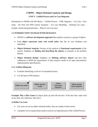
- 1. CS8592 Object Oriented Analysis and Design Unit I III IT Prepared by Kaviya.P, AP/IT Page 1 CS8592 – Object Oriented Analysis and Design UNIT I – Unified Process and Use Case Diagrams Introduction to OOAD with OO Basics – Unified Process – UML diagrams – Use Case –Case study – the Next Gen POS system, Inception – Use case Modelling – Relating Use cases – include, extend and generalization – When to use Use-cases 1.1 INTRODUCTION TO OOAD WITH OO BASICS OOAD is a software development approach that models a system as a group of objects. Each object represents some real world entity that has its own attributes and operations. Object Oriented Analysis: Focuses on the analysis of functional requirements of the system. Emphasis on finding and describing the objects or concepts in the problem domain. Object Oriented Design: Emphasis on defining software objects and how they collaborate to fulfill the requirements. It takes analysis model as an input and produces implementation specifications. 1.1.1 Artifact (Diagram) It entitles identifying a rich set of conceptual classes. It is the heart of OO analysis. Example: Play a Dice Game (A player picks up and rolls the dice. If the dice face value total seven, they win; otherwise, they lose.) a) Define Use Cases Use cases are not an object-oriented artifact, they are simply written stories. A popular tool in requirements analysis and are an important part of the Unified Process.
- 2. CS8592 Object Oriented Analysis and Design Unit I III IT Prepared by Kaviya.P, AP/IT Page 2 b) Define a Domain Model Object-oriented analysis is concerned with creating a description of the domain from the perspective of classification by objects. A decomposition of the domain involves an identification of the concepts, attributes, and associations. c) Define Interaction Diagrams Object-oriented design is concerned with defining software objects and their collaborations. A common notation to illustrate collaborations is the interaction diagram. It shows the flow of messages between software objects, and thus the invocation of methods.
- 3. CS8592 Object Oriented Analysis and Design Unit I III IT Prepared by Kaviya.P, AP/IT Page 3 d) Define Design Class Diagrams It is useful to create a static view of the class definitions with a design class diagram. It illustrates the attributes and methods of the classes. 1.1.2. Unified Modelling Language (UML) A language for specifying, visualizing, constructing, and documenting the artifacts of software systems, as well as for business modeling and other non-software systems. UML is composed of 9 graphical diagrams: 1. Class Diagram: Describes the structure of a system by showing the system's classes, their attributes, and the relationships among the classes. 2. Use-Case Diagram: Describes the functionality provided by a system in terms of actors, their goals represented as use cases, and any dependencies among those use cases. 3. Behavior Diagram a. Interaction Diagram i. Sequence Diagram: Shows how objects communicate with each other in terms of a sequence of messages. ii. Communication diagram: How the interactions between objects or parts in terms of sequenced messages. b. State Chart Diagram: Describes the states and state transitions of the system. c. Activity Diagram: Describes the business and operational step-by-step workflows of components in a system. An activity diagram shows the overall flow of control. 4. Implementation Diagram a. Component Diagram: Describes how a software system is split up into components and shows the dependencies among these components.
- 4. CS8592 Object Oriented Analysis and Design Unit I III IT Prepared by Kaviya.P, AP/IT Page 4 b. Deployment Diagram: Describes the hardware used in system implementations and the execution environments and artifacts deployed on the hardware. Three ways to Apply UML 1. Sketch: Informal and incomplete diagrams created to explore difficult parts of the problem or solution. (Eg: Agile Model) 2. Blueprint: Detailed designed diagrams (Reverse & Forward Engineering) 3. Programming Language: Complete executable specification of a software system. Executable code will be automatically generated. Three Perspectives to Apply UML 1. Conceptual Perspective: Describing things in a situation of the real world or domain of interest. 2. Specification (software) Perspective: Describe software abstractions or components with specifications and interfaces, but no commitment to a particular implementation. (Eg: Not specifically a class in C# or Java). 3. Implementation (software) Perspective: Describe software implementations in a particular technology (Eg: Java). Basic Concepts of Object Orientation Objects: A real world entity. Attributes or properties describe object‘s state (data) and methods define its behavior. Classes: To define the attributes and methods (the state and behavior) of its instances.
- 5. CS8592 Object Oriented Analysis and Design Unit I III IT Prepared by Kaviya.P, AP/IT Page 5 Inheritance: A relationship between classes where one class is the parent class of another (derived) class. To inherits all of the properties and methods (procedures) defined in its super class. (Super class & Sub class) Polymorphism: The same operation may behave differently on different classes. Abstraction: Hiding unwanted details while showing most essential information. Encapsulation: Binding the code and data into a single unit. Hiding is a principle of hiding internal data and procedures of an object. Protects the data from corruption. Example: class Student { int rollno; String name; void get_rollno(); void get_name(); } Structured Programming Vs. Object Oriented Programming Structured Programming Object Oriented Programming Focuses on process Focuses on data Top-down approach Bottom-up approach Less reusability More reusability 1.2 UNIFIED PROCESS (UP) A software development process describes an approach to building, deploying, and maintaining software. Unified Process is a popular iterative software development process for building object-oriented systems.
- 6. CS8592 Object Oriented Analysis and Design Unit I III IT Prepared by Kaviya.P, AP/IT Page 6 1.2.1 UP for three reasons 1. The UP is an iterative process. 2. UP provides a structure for how to do and thus how to explain OOA/D. 3. The UP is flexible, and can be applied in a lightweight and agile approach. 1.2.2 Iterative, Evolutionary and Agile Development Development is organized into a series of iterations (Mini-project). The outcome of each iteration is tested, integrated, and executable partial system. Each iteration includes its own requirements analysis, design, implementation, and testing activities. The system grows incrementally over time, iteration by iteration. Iterations are time-boxed or fixed in length. This approach is also known as iterative and incremental development. 1.2.3 Agile Modeling Best architecture. Requirements emerge from teams. It emphasizes UML as sketch to satisfy the customer through early and continuous delivery of valuable software. Example: DSDM, SCRUM
- 7. CS8592 Object Oriented Analysis and Design Unit I III IT Prepared by Kaviya.P, AP/IT Page 7 1.2.4 Benefits of Iterative Development Less project failure, better productivity, and lower defect rates. Early rather than late mitigation of high risks (technical, requirements, objectives, usability, and so forth). Early visible progress. Early feedback, user engagement, and adaptation, leading to a refined system that more closely meets the real needs of the stakeholders Managed complexity; the team is not overwhelmed by "analysis paralysis" or very long and complex steps The learning within iteration can be methodically used to improve the development process itself, iteration by iteration. 1.2.5 Best Practices in UP Tackle high-risk in early iterations Continuously engage users of evaluation, feedback and requirements. Continuously verify quality, test early, often and realistically. Develop software iteratively Manage requirements Use component based architecture Control changes to architecture 1.2.6 The UP Phases A UP project organizes the work and iterations across four major phases: 1. Inception: Approximate vision, business case, scope, vague estimates. 2. Elaboration: Refined vision, iterative implementation of the core architecture, resolution of high risks, identification of most requirements and scope, more realistic estimates. 3. Construction: Iterative implementation of the remaining lower risk and easier elements, and preparation for deployment. 4. Transition: Beta tests, deployment. Increment: The difference (delta) between the releases of two subsequent phases Δ = V2 – V1
- 8. CS8592 Object Oriented Analysis and Design Unit I III IT Prepared by Kaviya.P, AP/IT Page 8 1.2.7 The UP Disciplines Disciplines: A set of activities (and related artifacts) in one subject area, such as the activities within requirements analysis. An artifact is the general term for any work product: code, Web graphics, database schema, text documents, diagrams, models, and so on. There are several disciplines in the UP: Business Modeling: The Domain Model artifact, to visualize noteworthy concepts in the application domain. Requirements: The Use-Case Model and Supplementary Specification artifacts to capture functional and non-functional requirements. Design: The Design Model artifact, to design the software objects.
- 9. CS8592 Object Oriented Analysis and Design Unit I III IT Prepared by Kaviya.P, AP/IT Page 9 1.2.8 The Relationship between Disciplines and Phases 1.2.9 Development Case The choice of practices and UP artifacts for a project may be written up in a short document. Discipline Practice Artifact Iterations Inception I1 Elaboration E1… En Construction C1… Cn Transition T1… Tn Business Modelling Agile Modelling Req. workshop Domain Model s Requirements Req. workshop Vision box exercise Dot voting Use-Case Model s r Vision s r Supplementary Specification s r Glossary s r Design Agile Modelling Test-driven dev. Design Model s r SW Architecture Document s Data Model s r Implementation Test-driven dev. Pair programming Continuous integration Coding standards … Project Management Agile PM Daily SCRUM Meeting … … Sample Development Case: s – Start; r – Refine
- 10. CS8592 Object Oriented Analysis and Design Unit I III IT Prepared by Kaviya.P, AP/IT Page 10 1.3 INCEPTION It is the initial step to establish a common vision and basic scope for the project. It will include analysis of use cases, critical non-functional requirements, creation of business case and preparation of development environment. It may include the first requirements workshop, planning for the first iteration, and then quickly moving forward to elaboration. The purpose is not to define all the requirements, or generate a believable estimate or project plan. Envision the product scope, vision and business case. Duration: One or few weeks 1.3.1 What is Inception? Most projects require a short initial step in which the following kinds of questions are explored: What is the vision and business case for this project? Feasible? Buy and/or build? Rough estimate of cost: Is it $10K-100K or in the millions? Should we proceed or stop? 1.3.2 Inception Artifacts Artifact Comment Vision and Business Case Describes the high-level goals and constraints, the business case, and provides an executive summary. Use-Case Model Describes the functional requirements. Supplementary Specification Describes other requirements, mostly non-functional. Glossary Key domain terminology, and data dictionary. Risk List & Risk Management Plan Describes the risks (business, technical, resource, and schedule) and ideas for their mitigation or response. Prototypes and proof-of- concepts To clarify the vision, and validate technical ideas. Iteration Plan Describes what to do in the first elaboration iteration. Phase Plan & Software Development Plan Low-precision guess for elaboration phase duration and effort. Tools, people, education, and other resources. Development Case A description of the customized UP steps and artifacts for this project. In the UP, one always customizes it for the project.
- 11. CS8592 Object Oriented Analysis and Design Unit I III IT Prepared by Kaviya.P, AP/IT Page 11 1.3.3 When you didn’t understand inception? No Business Case or Vision artifact. The names of most of the use cases and actors were not identified An attempt to define most of the requirements. Takes more than "a few" weeks long for most projects. Estimates or plans are expected to be reliable. None of the use cases were written in detail. 1.3.4 How much UML during Inception? UML use case diagrams are drawn and not much diagram is warranted, UML diagrams will occur in the elaboration phase, Only 10% of requirements are expressed in text forms. 1.3.5 Evolutionary Requirements Requirements: capabilities and conditions to which the system must confirm. A primary challenge of requirement analysis is to find, communicate and remember (write down) what is really needed. Requirements keep on changing throughout the system development. The systematic approach to find, document, organize and track the changing requirements of a system has to be followed. Waterfall Requirements Evolutionary Requirements The approach of full requirement definition followed by a long gap to the next phase. Spending significant time and effort in analysis phase is inappropriate. Frequent stake-holders participation, evolution and feedback on requirements take place to gather the requirements. Types of Requirements: (According to FURPS+) o Functional: features, capabilities, security. o Usability: human factors, help, documentation. o Reliability: frequency of failure, recoverability, predictability. o Performance: response times, throughput, accuracy, availability, resource usage. o Supportability: adaptability, maintainability, internationalization, configurability
- 12. CS8592 Object Oriented Analysis and Design Unit I III IT Prepared by Kaviya.P, AP/IT Page 12 The "+" in FURPS+ indicates ancillary and sub-factors, such as: o Implementation: resource limitations, languages and tools, hardware. o Interface: constraints imposed by interfacing with external systems. o Operations: system management in its operational setting. o Packaging o Legal: licensing Requirement Artifacts Artifacts Comment Use-Case Model Describes the functional requirements. Supplementary Specifications Describes other requirements, mostly non-functional. Glossary Key domain terminology, and data dictionary. Vision Describes the high-level goals and constraints, the business case, and provides an executive summary. Business Rules Domain Rules. Describe requirements or polices that transcend one software project 1.4 USE CASE MODELLING Use cases are text stories, used to discover and record requirements. Use cases: Actor using a system to meet goals. Sequence of actions Different tasks that user can perform while interacting with the system. 1.4.1 Definition: Actors, Scenarios, and Use Cases An actor is something with behavior, such as a person, computer system, or organization; for example, a cashier. A scenario is a specific sequence of actions and interactions between actors and the system; it is also called a use case instance. A use case is a collection of related success and failure scenarios that describe an actor using a system to support a goal. 1.4.2 Use Cases & Use-Case Model Use cases are text documents, not diagrams, Use-case modeling is primarily an act of writing text, not drawing diagrams. The Use-Case Model shows the names of use cases and actors, and their relationships.
- 13. CS8592 Object Oriented Analysis and Design Unit I III IT Prepared by Kaviya.P, AP/IT Page 13 1.4.3 Why Use Cases? Make domain experts or requirement donors to write use cases. Emphasize the user goals and perspective Question "Who is using the system, what are their typical scenarios of use, and what are their goals?" 1.4.4 Three Kinds of Actors An actor is anything with behavior, including the system under discussion (SuD) itself when it calls upon the services of other systems. Actors are roles played not only by people, but by organizations, software, and machines. There are three kinds of external actors in relation to the SuD: o Primary actor: User goals fulfilled through using services of the SuD. Example: the cashier. – Why identify? To find user goals, which drive the use cases. o Supporting actor: Provides a service (for example, information) to the SuD. Example: Automated payment authorization service. Often a computer system, but could be an organization or person. – Why identify? To clarify external interfaces and protocols. o Offstage actor: An interest in the behavior of the use case, but is not primary or supporting. Example: A government tax agency. – Why identify? To ensure that all necessary interests are identified and satisfied. Offstage actor interests are sometimes subtle or easy to miss unless these actors are explicitly named. 1.4.5 Three Common Use Case Formats Brief: Terse one-paragraph summary, usually of the main success scenario. It was created during early requirements analysis, to get a quick sense of subject and scope. May take only a few minutes to create. Casual: Informal paragraph format. Multiple paragraphs that cover various scenarios. It was created during early requirements analysis, to get a quick sense of subject and scope. May take only a few minutes to create.
- 14. CS8592 Object Oriented Analysis and Design Unit I III IT Prepared by Kaviya.P, AP/IT Page 14 Fully Dressed: All steps and variations are written in detail, and there are supporting sections, such as preconditions and success guarantees. It was created , after many use cases have been identified and written in a brief format, then during the first requirements workshop a few of the architecturally significant and high-value use cases are written in detail. Use Case Section Comment Use Case Name Start with a verb. Scope The system under design. Level "user-goal" or "subfunction" Primary Actor Calls on the system to deliver its services. Stakeholders and Interests Who cares about this use case, and what do they want? Preconditions What must be true on start, and worth telling the reader? Success Guarantee What must be true on successful completion, and worth telling the reader? Main Success Scenario A typical, unconditional happy path scenario of success. Extensions Alternate scenarios of success or failure. Special Requirements Related non-functional requirements. Technology and Data Variations List Varying I/O methods and data formats. Frequency of Occurrence Influences investigation, testing, and timing of implementation. Miscellaneous Such as open issues. 1.4.6 Use Case: Process Sale: Fully Dressed Format Example Scope: NextGen POS application Level: User Goal Primary Actor: Cashier Stakeholders and Interests: - Cashier: Wants accurate, fast entry, and no payment errors, as cash drawer shortages are deducted from his/her salary. - Salesperson: Wants sales commissions updated. - Customer: Wants purchase and fast service with minimal effort. Wants easily visible display of entered items and prices. Wants proof of purchase to support returns.
- 15. CS8592 Object Oriented Analysis and Design Unit I III IT Prepared by Kaviya.P, AP/IT Page 15 - Company: Wants to accurately record transactions and satisfy customer interests. Wants to ensure that Payment Authorization Service payment receivables are recorded. Wants some fault tolerance to allow sales capture even if server components (e.g., remote credit validation) are unavailable. Wants automatic and fast update of accounting and inventory. - Manager: Wants to be able to quickly perform override operations, and easily debug Cashier problems. - Government Tax Agencies: Want to collect tax from every sale. May be multiple agencies, such as national, state, and county. - Payment Authorization Service: Wants to receive digital authorization requests in the correct format and protocol. Wants to accurately account for their payables to the store. Preconditions: Cashier is identified and authenticated. Success Guarantee (or Postconditions): Sale is saved. Tax is correctly calculated. Accounting and Inventory are updated. Commissions recorded. Receipt is generated. Payment authorization approvals are recorded. Main Success Scenario (or Basic Flow): 1. Customer arrives at POS checkout with goods and/or services to purchase. 2. Cashier starts a new sale. 3. Cashier enters item identifier. 4. System records sale line item and presents item description, price, and running total. Price calculated from a set of price rules. Cashier repeats steps 3-4 until indicates done. 5. System presents total with taxes calculated. 6. Cashier tells Customer the total, and asks for payment. 7. Customer pays and System handles payment. 8. System logs completed sale and sends sale and payment information to the external Accounting system (for accounting and commissions) and Inventory system (to update inventory). 9. System presents receipt. 10. Customer leaves with receipt and goods (if any). Extensions (or Alternative Flows): *a. At any time, Manager requests an override operation: 1. System enters Manager-authorized mode. 2. Manager or Cashier performs one Manager-mode operation. e.g., cash balance change, resume a suspended sale on another register, void a sale, etc. 3. System reverts to Cashier-authorized mode. *b. At any time, System fails: To support recovery and correct accounting, ensure all transaction sensitive state and events can be recovered from any step of the scenario. 1. Cashier restarts System, logs in, and requests recovery of prior state. 2. System reconstructs prior state. 2a. System detects anomalies preventing recovery: 1. System signals error to the Cashier, records the error, and enters a clean state. 2. Cashier starts a new sale.
- 16. CS8592 Object Oriented Analysis and Design Unit I III IT Prepared by Kaviya.P, AP/IT Page 16 1a. Customer or Manager indicates to resume a suspended sale. 1. Cashier performs resume operation, and enters the ID to retrieve the sale. 2. System displays the state of the resumed sale, with subtotal. 2a. Sale not found. 1. System signals error to the Cashier. 2. Cashier probably starts new sale and re-enters all items. 3. Cashier continues with sale (probably entering more items or handling payment). 2-4a. Customer tells Cashier they have a tax-exempt status (e.g., seniors, native peoples) 1. Cashier verifies, and then enters tax-exempt status code. 2. System records status (which it will use during tax calculations) Special Requirements: - Touch screen UI on a large flat panel monitor. Text must be visible from 1 meter. - Credit authorization response within 30 seconds 90% of the time. - Somehow, we want robust recovery when access to remote services such the inventory system is failing. - Language internationalization on the text displayed. - Pluggable business rules to be insertable at steps 3 and 7. - … Technology and Data Variations List: *a. Manager override entered by swiping an override card through a card reader, or entering an authorization code via the keyboard. 3a. Item identifier entered by bar code laser scanner (if bar code is present) or keyboard. 3b. Item identifier may be any UPC, EAN, JAN, or SKU coding scheme. … Frequency of Occurrence: Could be nearly continuous. Open Issues: - What are the tax law variations? - Explore the remote service recovery issue. - What customization is needed for different businesses? - Must a cashier take their cash drawer when they log out? - Can the customer directly use the card reader, or does the cashier have to do it? 1.4.7 Guidelines 1. Write in an Essential UI-Free Style a. Essential Style Writing: Write use cases in an essential style; keep the user interface out and focus on actor intent b. Concrete Style: User interface decisions are embedded in the use case text. The text may even show window screen shots, discuss window navigation, GUI widget manipulation and so forth.
- 17. CS8592 Object Oriented Analysis and Design Unit I III IT Prepared by Kaviya.P, AP/IT Page 17 2. Write Terse Use Cases: Delete "noise" words. Even small changes add up, such as "System authenticates…" rather than "The System authenticates…" 3. Write Black-Box Use Cases: Black-box use cases are the most common and recommended kind; they do not describe the internal workings of the system, its components, or design. 4. Take an Actor and Actor-Goal Perspective: A set of use-case instances, where each instance is a sequence of actions a system performs that yields an observable result of value to a particular actor. 5. To Find Use Cases a. Choose the System Boundary b. Find Primary Actors and Goals c. Identify the goals for each primary actor d. Define use cases that satisfy user goals 6. Tests To Find Useful Use Cases a. The Boss Test: To check for achieving results of measurable value. It may be a use case at some low goal level, but not the desirable level of focus for requirements analysis. b. The EBP (Elementary Business Process) Test: Focus on use case that reflects the business process. A task performed by one person in one place at one time, in response to a business event, which adds measurable business value and leaves the data in a consistent state, e.g., Approve Credit or Price Order c. The Size Test: Use case is a single action or a sequence of actions, all type of actions is selected. 1.5 The Next Gen POS system It is a next generation Point of Sale System, a computerized application used to record sales and handle payments. It is used in retail stores. It includes hardware components such as computer, barcode scanner, printer and software to run a system.
- 18. CS8592 Object Oriented Analysis and Design Unit I III IT Prepared by Kaviya.P, AP/IT Page 18 Use Case Diagram It is the model for system functionality and environment. It captures the goals of each user and their responsibilities. 1.7 RELATING USE CASES The Use Case Model describes the proposed functionality of the new system. A Use Case represents a discrete unit of interaction between a user (human or machine) and the system. A Use Case may 'include' another Use Case's functionality or 'extend' another Use Case with its own behavior. The formal specification of a Use Case includes: o Requirements: formal functional requirements that a Use Case must provide to the end user. o Constraints: formal rules and limitations that a Use Case operates under, and includes pre- post- and invariant conditions. o Scenarios: formal descriptions of the flow of events that occurs during a Use Case instance.
- 19. CS8592 Object Oriented Analysis and Design Unit I III IT Prepared by Kaviya.P, AP/IT Page 19 1.7.1 Types of Use Cases Concrete Use Case: Initiated by an actor and performs the entire behavior desired by the actor. These are the elementary business process use cases. Example: Process Sale. Abstract Use Case: Never instantiated by itself. It is a sub-function use case that is part of another use case. Example: Handle Credit Payment. Base Use Case: It includes another use case or it is extended or specialized by another use case. Example: Process Sale includes Handle Credit Payment Addition Use Case: The use case that is an inclusion, extension, or specialization is called an addition use case. Example: Handle Credit Payment added with Process Sale Addition use cases are usually abstract. Base use cases are usually concrete. 1.7.2 Kinds of Relationships An organization mechanism to improve communication and comprehension of the use cases, reduce duplication of text, and improve management of the use case documents. 1. The include Relationship: It is common to have some partial behavior that is common across several use cases. The include relationship could be used: a. To simplify large use case by splitting it into several use cases b. To extract common parts of the behaviors of two or more use cases. Example: Base use case is incomplete without derived use case. include Customer Authentication use case Deposit Funds and Withdraw Cash use cases 2. The extend Relationship: The idea is to create an extending or addition use case, and within it, describe where and under what condition it extends the behavior of some base use case.
- 20. CS8592 Object Oriented Analysis and Design Unit I III IT Prepared by Kaviya.P, AP/IT Page 20 Example: Base use case is completed with / without derived use case. 3. The Generalization Use Case: The activity of identifying commonality among concepts and defining superclass (general concept) and subclass (specialized concept) relationships. Child use case inherits properties and behavior of the parent use case and may override the behavior of the parent. Base use case could be abstract. Example (Include, Extends, Generalization):