This document discusses the equal-friction method of designing an air conditioning system duct layout to distribute 36,000 cfm of air through 18 outlets at 0.2 in wg pressure. [1] It outlines the steps to size the main duct at 46x46 inches and branch ducts to maintain equal friction. [2] Calculations determine the total duct friction loss is 0.3315 in wg. [3] The required fan static discharge pressure is calculated to be 0.3215 in wg.
1. AIR-CONDITIONING SYSTEMS DUCT – EQUAL-FRICTION METHOD
An industrial air-conditioning system requires 36000 cfm of air. This low-velocity system will be fitted with enough air outlets to distribute the
air uniformly throughout the conditioned space. The required operating pressure for each duct is 0.20 in wg. Determine the duct sizes
required for this system by using the equal-friction method of design. What is the required fan static discharge pressure?
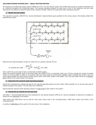
1. Sketch the duct system
The required air quantity, 3600 ft3/min, must be distributed in approximately equal quantities to the various areas in the building. Sketch the
proposed duct layout.
Determine the required capacity of each air outlet from air quantity required, ft3/min.
ft 3
36000 3
air quantity per outlet = min = 2000 ft per outlet
18 min
This is within the usual range of many commercially available outlets.
Where the required capacity outlet is extremely large, say 10000 ft3/min, or extremely small, say 5 ft3/min, change the number of outlets
shown on the duct sketch to obtain an air quantity within the usual range of commercially available outlets. Relocate each outlet in the so it
serves approximately the same amount of floor area as each of the other outlets in the system. Thus, the duct sketch serves as a trial-and-
error analysis of the outlet location and capacity.
2. Determine the required outlet operating pressure
Consult the manufacturer’s engineering data for the required operating pressure of each outlet. Where possible, try to use the same type of
outlets throughout the system. This will reduce the investment.
Assume that the required outlet operating pressure is 0.20-in wg for each outlet in this system.
3. Choose the air velocity for the main duct
Use Table 7 – Recommended Maximum Duct Velocities for Low Velocity Systems (FPM) by Dr. Carriers Handbook, to determine a suitable air
velocity for the main duct of this system.
Table shows that 2500 ft/min can be used for main ducts where noise is the controlling factor; 3000 ft/min where duct friction is the
controlling factor.
A velocity of 2500 ft/min will be used for the main duct in this installation.
2. 4. Determine the dimensions of the duct
The require duct area:
ft 3 / min 36000 ft 3 / min
A = = = 14.4 ft 2
ft / min 2500 ft / min
A nearly square duct: 46 x 45-in has an area of 14.38 ft2 and is a good first choice for this system because it is closely
approximates the outlet size of a standard centrifugal fan.
Where possible, use a square main duct to simplify fan connections.
Thus a 46 x 46-in duct might be the final choice for this system.
5. Determine the main-duct friction loss
0.50 0.50
⎛ 144 A ⎞ ⎛ 144 * 14.4 ft 3 ⎞
Convert the required duct area to the equivalent diameter in inches d, using: d = 2 ⎜
⎜ π ⎟
⎟ =2 ⎜
⎜
⎟
⎟ = 51.5 in .
⎝ ⎠ ⎝ π ⎠
Enter Chart 7 – Friction Loss for Round Duct by Dr. Carrier Handbook at 36000 ft3/min and project horizontally to a round duct diameter of
in wg
51.5-in. At the top of the chart read the friction loss as 0.13 .
100 ft of equivalent length
6. Size the branch ducts
For many common air-conditioning systems the equal-friction method is used to size the ducts. In this method the supply, exhaust, and
return-air ducts are sized so they have the same friction loss per foot of length for the entire system.
The usual procedure in the equal-friction method is to select an initial air velocity in the main duct near the fan, using the sound level as the
limiting factor.
Compute the duct areas, using Table 13 – Percent Section Area in Branches for Maintaining Equal Friction by Dr. Carriers Handbook. Tabulate
the results, using the duct run having the highest resistance. The friction loss through all elbows and fittings in the section must be included.
The total friction loss in the duct having the highest resistance is the loss the fan must overcome.
By inspection of the duct layout, shows that the duct run from the fan to the outlet 18 has the highest resistance because it is the longest
run.
Column 1 lists the longest duct run in the system.
Column 2, the air leaving the outlets in branch A, (6 outlets)(2000 ft3/min) = 12000 ft3/min, is subtracted from the quantity of air, 36000
ft3/min, discharge by the fan to give the air quantity flowing from A-B. A similar procedure is followed for each successive duct and air
quantity.
Column 3, is found by dividing the air quantity in each branch listed in columns 1 and 2 by 36000 ft3/min, and multiplying the result by 100.
12000 ft3 / min
Thus for column B-13: * 100% = 33%
36000 ft3 / min
Column 4 values are found from Table 13 - Percent Section Area in Branches for Maintaining Equal Friction by Dr. Carriers Handbook. Enter
that table with ft3/min capacity from column 3 and read the duct area, percent.
Thus for column 13-14, with 28% cfm capacity, the % duct area is 35.3%.
Column 5 values show the area of the duct, in sqm.
( )
Thus for column 13-14, ductarea = 14.4 ft2 (0.355) = 5.1 ft2
Convert the duct area to nearly square, or a square, duct by finding two dimensions that will produce the desired area.
Column 6 values shows the nearly square dimensions of the duct. Table 6 – Duct dimensions, Section Area, Circular Equivalent Diameter, and
Duct Class by Dr. Carrier Handbook is used to select the rectangular duct sizes.
Duct sections A through 6 and B through 12 have the same dimensions as the corresponding duct sections B through 18.
3. 7. Find the total duct friction loss
Examination of the duct sketch indicates that the duct run from the fan to outlet 18 has the highest resistance. Compute the total duct run
length and the equivalent of the two elbows in the run as shown.
Column 3, duct length, is determined from the sketch
Column 4, are the equivalent length of the duct elbows can be found in Table 12 – Friction of Rectangular Elbows by Dr. Carriers Handbook.
The total equivalent length = (column 1) + (column 2) = 255 ft.
8. Compute the duct friction loss
Use the general relation: hL = L f
Where: hL = total friction loss in duct, in wg
L = total equivalent duct length, ft
f = friction loss for the system, in wg per 100 ft.
Hence;
( )
⎛
hL = 255 ft ⎜ 0.13
⎜
in wg ⎞
⎟ = 0.3315 − in wg
100 ft of equivalent length ⎟
⎝ ⎠
9. Determine the required fan static discharge pressure
Total static pressure required at the fan discharge = outlet operating pressure + duct loss – velocity regain between first and last duct section
The velocity for duct section A:
ft 3
36000
vA = min = 2500 ft
14.4 ft 2 min
The velocity for duct last section:
ft 3
2000
v 18 = min = 1333.33 ft
1.5 ft 2 min
When the fan discharge velocity is higher than the duct velocity in an air-conditioning system, compute for Static Pressure Regain, R by:
⎡⎛ v ⎞ 2 ⎛ v ⎞ 2 ⎤
R = 0.75 ⎢⎜ f
⎟ −⎜ ⎜ 4000 ⎟ ⎥
d
⎢⎜ 4000 ⎟
⎝ ⎠ ⎝
⎟ ⎥
⎠ ⎦
⎣
Where: vf = fan outlet velocity, ft/min
vd = duct velocity, ft/min
⎡⎛ 2
⎞ ⎤
2
2500 ft / min ⎞ ⎛
⎟ − ⎜ 1333.33 ft / min ⎟ ⎥ = 0.21 − in wg
R = 0.75 ⎢⎜
⎢⎜ 4000 ⎟ ⎜ 4000 ⎟ ⎥
⎣⎝ ⎠ ⎝ ⎠ ⎦
Hence;
Total static pressure required at the fan discharge = (0.20 + 0.3315 – 0.21) – in wg
Total static pressure required at the fan discharge = 0.3215-in wg
4. Figure below shows the detail of duct hanger for ducts of various dimensions.
Figure below shows the details of rectangular duct takeoffs for air supply to specific rooms or areas.
NOTE: The equal-friction method of air-conditioning system duct design are applicable only to low-velocity systems in which the maximum air
velocity is 3000 ft/min, or less.