Red Herrings (Advanced Mtrls)
•
0 gefällt mir•82 views

This case study describes an investigation into failures of fuel float switches in aircraft. Over the course of the investigation, four potential failure scenarios were identified but ultimately proved to be "red herrings" or misleading. Through a process of elimination and further testing, the true root cause was determined to be solder creep in the electrical connections of some switches. Solder creep had led to failure of the joints through incremental deformation over many load cycles. This root cause was only identified after reconsidering assumptions made early in the investigation.

Empfohlen
Empfohlen
Weitere ähnliche Inhalte
Ähnlich wie Red Herrings (Advanced Mtrls)
Ähnlich wie Red Herrings (Advanced Mtrls) (20)
Red Herrings (Advanced Mtrls)
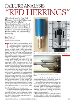
- 1. This article is based on Four Red Herrings, Float Switch Failure, and a Case of Multiple Failure Scenarios, a case study presented at MS&T’08. It covers investigation of fuel float switches in which evidence was found to support several proposed failure scenarios that were ultimately misleading. Paul DeVries* Boeing Corporation Huntington Beach, California T his case history summarizes findings of four separate investigations involving the failure of a certain model of electrical fuel float switch in which several plausible but ulti- mately “red herring” failure scenarios were pursued. It underscores the danger of assumptions and the value of both expert knowledge and broad-based ex- perience. The true root cause was solder creep, but this was determined only after a re-examination of preliminary failure mode assumptions. The investigation began after an air carrier com- plained of unacceptably short service life for float switches from a particular manufacturer. Switch failure was typically identified by an open circuit when the switch should have been closed. The switches, which should have lasted many years and millions of cycles, were failing after as little as twenty- one months in service. The part cost of switches was low, but failed switches could ground an air- craft and require the affected fuel tank to be emp- tied and vented before the switch could be replaced. The float switch mechanism consisted of a glass bead containing two stationary switch contacts and a flexible magnetic reed (Fig. 1). The glass switch bead was encased in a metallic tubular housing that ran through the center of the float and was con- nected to the system via electrical leads soldered to the contacts by a lap-style solder joint. Magnets mounted in the float forced the switch closed (Fig. 2) when the float was raised to a predetermined height. Red Herring #1: Excessive contact current The original set of three failed switches was eval- uated by the manufacturer, who found they were mechanically sound but concluded that contacts had been “burned” due to current overloads in ex- cess of their electrical rating. Proposed causes for *Member of ASM International current overload included a short circuit in the air- craft electrical system or accidental high current im- posed during electrical system maintenance. Following the manufacturer’s evaluation, the switch contacts (Fig. 3) were forwarded to the Boeing Metallurgical Laboratory for corroborative evaluation. Due to the manufacturer’s extensive ex- perience with these switches, the reported failure mode was taken at face value and attempts were made to identify evidence of electrical overload or excessive contact resistance. All contacts had been plated with rhodium, which typically exhibited a dull finish with a light to medium-brown-yellow patina, and small burnished ADVANCED MATERIALS & PROCESSES/DECEMBER 2008 23 Fig. 1— a) Photo of float switch; b) X-ray image showing float switch design. SShheellll 00..001100 iinncchh 00..000055 iinncchh SSttaattiioonnaarryy FFllooaatt ccoonnttaaccttss ((nnoott vviissiibbllee)) FFllooaatt ccoouunntteerrwweeiigghhtt RReeeedd ccoonnttaacctt TToopp wwiirree GGllaassss sswwiittcchh TToopp wwiirree bbeeaadd ssoollddeerr jjooiinntt HHoouussiinngg RReeeedd ssoollddeerr jjooiinntt FAILURE ANALYSIS “RED HERRINGS” aa bb Fig. 2 — Close-up of the switch contacts in the “closed” position. Fail analysis.qxp 11/18/2008 2:31 PM Page 1
- 2. areas of metal-to-metal contact. None of the con- tacts displayed arc burns; however, tinting on some samples suggested possible exposure to elevated temperatures. Metallographic analysis revealed an equiaxed microstructure with no apparent grain growth, suggesting that excessive currents had not been encountered. Apart from reliance on the manufacturer’s state- ment of “burned contacts,” the slight discoloration noted on some contacts was the only thing that sug- gested possible overheating. No solid evidence of excessive contact resistance, mechanical failure, or excessive current was found. Two fortunate but wholly coincidental events con- clusively netted this “red herring.” The first occurred during contact resistance testing when an inadver- tent capacitor discharge momentarily routed a cur- rent spike through a new switch, resulting in local- ized arcing and subsequent welding of the switch contacts.As arc-induced welding and pitting were completely absent from all failed switch contacts, momentary excessive over-current resulting from improper system testing was dismissed as a pos- sible failure mode. The second event emerged as collateral informa- tion from an unrelated testing program evaluating the effects of sustained high current loads on float switches made by the same manufacturer. During testing, one switch was subjected to 15 amps DC for two minutes before failure in the solder joint at- tached to the stationary contact. The microstructure of the reed contact subjected to short-term current overload differed little from that seen in failed switches. Conversely, current overload (15 Amps DC for 20 minutes) was sufficient to produce con- tact melting and significant grain growth in adja- cent material. Overcurrent testing had demonstrated that switch contacts could withstand loads 20 times greater than the switch rating and 33 times greater than the maximum current anticipated from the electrical system. In short, the “burned contact” hy- pothesis was a “red herring.” Red Herring #2: Flaking magnets X-ray inspection of twelve additional failed switches found that eleven were mechanically func- tional. Thus, insufficient magnetic field strength was dismissed as a possible failure mode. Subsequent sectioning of the twelve float assem- blies found eight whose magnets exhibited a scaly, flaky topography. The flaking condition suggested several possible float-jamming mechanisms, such as the buildup of loose flake material jamming be- tween the housing tube and bushing, or magnet swelling and spalling that could effectively clamp the magnets onto the housing tube. To support failure analysis, fourteen fully opera- tional switches were removed from an in-service aircraft. The magnets in all but the newest of these switches exhibited some type of flaking.. The float from a new off-the-shelf switch unit was evaluated for comparison purposes. As ex- pected, the new magnets did not exhibit the flaking phenomena. A possible explanation for magnet flaking emerged when Fourier Transform Infrared (FTIR) spectroscopy determined that the phthalate oil plasticizer found in the new magnet matrix ma- terial was missing from most of the failed switch magnets. The new switch magnet was immersed in hot (140ºF) Jet ‘A’ fuel for two weeks; subsequent FTIR testing confirmed that the fuel had leached the phthalate oil from the magnet matrix. While circumstantial evidence supported the “magnet flaking/float jamming” hypothesis, sev- eral irreconcilable observations refuted it. For ex- ample, four of the failed switch float assemblies had not displayed a flaky magnet topography, yet one of these floats exhibited definite jam-like evidence. Also of the eight failed float switches whose mag- nets exhibited flaking, only three of the floats exhib- ited magnetic debris on the float bushings where jamming would likely occur. Lastly, while lab ex- periments demonstrated that fuel could leach plas- ticizer from magnets, this did not result in a pro- gressive magnet flaking phenomenon. Despite the prevalence of magnet flaking and ev- idence of magnetic debris on some bushings, flake- related float jamming could not be positively con- firmed. By contrast, the float with the most definite jam-like evidence was an assembly whose magnets displayed no significant flaking. Given the amount of circumstantial evidence, the hypothesis was not entirely dismissed. However, the data inconsis- tencies suggested the failure hypothesis was a red herring. Red Herring #3: Dimensional interference During investigation of the flaking phenomenon on the magnets, note was made of circumferential striation-like marks that were attributed to contact with the tubular housing. While the cause of magnet flaking remained unresolved (it could not be repro- duced in the lab) occasional non-concentricity noted between the float, the magnets, and the bushings suggested that a lack of dimensional control com- bined with magnet flaking or swelling might pro- duce the “clamping action” these striation-like marks seemed to indicate. This hypothesis was aided by the observation of occasional axial scuff marks and worn epoxy nodules noted on some magnets. Drawing dimensions for the float assembly had not been provided; however, diametric analysis based on dimensions from the new off-the-shelf float 24 ADVANCED MATERIALS & PROCESSES/DECEMBER 2008 Metallo- graphic analysis revealed an equiaxed micro- structure with no apparent grain growth, suggesting that excessive currents had not been encountered. Fig. 3— Switch contacts as received from the manufacturer. Fail analysis.qxp 11/18/2008 2:31 PM Page 2
- 3. assembly (i.e. a magnet with no flaking) produced estimated diametric clearances as low as 0.003 inch. The presence of epoxy deposits on the magnet ID would likely exacerbate any clearance problems, and the wear noted on some of these deposits indi- cated contact between the epoxy deposits and the switch housing tube. Although flaking could conceivably eliminate this clearance, it could not be proven conclusively that it had done so. As the magnet flaking phe- nomena had not successfully been reproduced in the laboratory, analysis could not prove that the flaking mechanism would actually produce forces large enough to effectively clamp the float assembly onto the tubular housing. While the hypothesis could not be completely dismissed, the fact that none of the floats had actually been stuck at the time the failed switches arrived at the laboratory sug- gested this failure mechanism was a “red herring.” Red Herring #4: An inappropriate assumption Tubular metal conduit typically carries electrical lead wires from the fuel float switch to a circuit ter- minal block.As a result, the analysis presumed that vibration loads on the electrical leads would be neg- ligible, and that the conduit could not place a ten- sile load on the lead wires. Solder joint failures were presumed to be caused by overload incurred during switch removal. So firm was this conviction that a detailed solder joint investigation had effectively been precluded from investigation. As the previous three failure hypotheses had proven false, unlikely, or lacking support, and as over half of the failed switches had been received with some form of solder joint damage, investiga- tors were forced to consider this assumption a self imposed “red herring,” and initiated serious inves- tigation into the solder joint failure. The investigation returned to the fourteen switches which had been removed from an in- service aircraft. Two of these switches already con- tained solder joint failures; the remaining twelve switches were subjected to tensile testing. Calculations estimated a joint strength of 26 pounds; however, actual tensile test values ranged from 8 to 23 pounds, with an average value (17 pounds) approximately half that of the bulk elec- trical wire itself. At the time it was not suspected that these “baseline” solder joints might be under- going failure by creep, which could explain such widely varying results. The lab-induced solder joint failure occurred by solder shear, by tensile overload of individual wire strands, or by a combination of both. Solder shear failures exhibited a dimpled-rupture morphology, while wire strand failures exhibited necking – both typical of ductile overload. Poor solder wetting, ap- parent on a number of wire leads, may have con- tributed to low solder joint tensile properties. Solder had adhered to the surface strands but had fre- quently failed to fully penetrate the wire bundle. This effectively created a “solder shell” around solder-free inner strands. Failure in these joints pro- duced necking and dimple rupture in the outer strands, while unsoldered inner strands simply pulled out of the “solder shell.” Of the failed switches, six were available for solder joint evaluation. Four of these switches exhibited separation of the electrical leads, while two had solder joints that remained intact. Scanning electron microscopy of the failed joints found that fractures typically occurred through the solder, producing a smeared, grainy fracture sur- face. Chatter marks were noted on two of the frac- ture faces. These marks were closely spaced at one end, but the spacing gradually increased as they progressed from one end of the joint to the other. Examination of intact joints often found evidence of joint deformation accompanied by surface cracking that displayed the same grainy texture seen in the failed solder joint fractures. The intergranular nature of the failures suggested failure by creep rupture. Creep is known to occur in solder at sustained loads much lower than the solder tensile strength. Creep would be exacerbated by the small joint size and lack of wetting noted during tensile testing. The presence of chatter marks supported an incremental deformation scenario (e.g. creep), and suggested a cyclical loading element in the failure process. Ironically, the granular nature of solder joint failure had been observed in passing early in the in- vestigation. The analyst, being unfamiliar with the appearance of creep, had noted it as interesting and unusual, but had not viewed it as significant.As the need for substantive solder failure analysis grew, creep was reconsidered as a possible failure mode. Readily available references contained limited in- formation on the characteristics of creep. However, consultation with a solder expert con- firmed the intergranular nature of creep rupture and revealed that creep often produces a “coarsened band” microstructure in the plane of the strain (Fig. 4). The “coarsened band” phenomenon had not been found during the literature search of common reference materials. Subsequent re-evaluation of available solder joints found that six of fifteen faulty switches had failed via solder creep, three had failed by other means (presumably float jamming), and six could not be evaluated (data could no longer be obtained). For more details about the investigation, please contact the author. For more information: Paul DeVries, Boeing Co., Huntington Beach, CA 90706; tel: 714/372-9411; paul.h.devries@boeing.com; www.boeing.com. ADVANCED MATERIALS & PROCESSES/DECEMBER 2008 25 Fig. 4 — Deformed solder joint displays a coarsened band (arrow) as well as probable mechanism for producing chatter marks (dashed arrow). Fail analysis.qxp 11/18/2008 2:31 PM Page 3