2. Kirchoff law
In 1854 Kirchoff
announced the two
laws that are still the
basis for most circuit
analysis techniques
3. Kirchoff law
Kirchoff Current law (KCL)
Kirchoff’s first Law, known as
Kirchoff’s Current Law (KCL), states
that current flows uniformly in a
circuit (At any node the sum of the
currents flowing into the node is
exactly equal to the sum of the
currents flowing out of the node)
I1 + I2 + I3= I4 + I5 = 0
So for the giving node:
4. For the circuit giving, write a KCL equation at
every node in the circuit in terms of the
current variables whose reference directions
are given:
Example :
I3
I4
I2
I1
IS
Kirchoff Current law (KCL)
Kirchoff law
5. Node a: I1 + I2 = I3 + Is
Node b: I2 = I3 + I4
Node c: Is = I1 + I4
a b
c
Example :
Kirchoff Current law (KCL)
Kirchoff law
7. Kirchoff Voltage law (KVL)
V1 = V2 + V3 + V4
Kirchoff’s second Law, known as
Kirchoff’s Voltage Law (KVL),
states that the sum of the
voltages is a closed loop is
always equal to zero.
So for the circuit here:
Kirchoff law
8. Node Analysis
When analyzing more complex
circuits, engineers usually make
use of one of the more powerful
techniques available.
One of the most popular of these
is the “Node Analysis Method”.
The “Node Analysis Method” is a
well organized technique which
relies on KCL
Equations are written for every
unknown node. The method is
best illustrated with an example.
9. Example:
Consider the giving circuit.
voltages at node A = +3V, node C is -10V.
Only node B is unknown
Current at node B, by KCL
∑ Iin = ∑ Iout or I1 = I2 + I3
Using Ohm’s Law,
VB = -1 V
Node Analysis
10. Q:When is the Node Analysis Method most
useful?
A:When there are only a few unknown node
voltages.
Node Analysis
11. VS
V1 V3
V4
++
+
+
_ _
_
_
Example: The circuit below contains four elements
and a voltage source. Write a sufficient set of
KCL equations to fully constrain all the
currents in the circuit. Let the current flowing
into the element with voltage V1 be I1, etc.?
I1 = I4
I1 + I2 + iS = 0
KCL at node a:
KCL at node b:
a b
Node Analysis
12. Quiz: Find current I3 in the circuit below, using
Node Analysis Method?
-1.64 mA +1.64 mA -3.82 mA
I1 = (3-VB)/R1 = (3-VB)/1000
I2 = (VB+9)/R2 = (VB+9)/1500
I3 = (VB)/R3 = (VB)/500
I1 = I2 + I3
VB = -.82 V
I3 = -1.64 mA
Node Analysis
13. Quiz: Find current I3 in the circuit below, using
the Node Analysis Method
-1.64 mA +1.64 mA 0 mA
Node Analysis
14. Example: Write a KVL equations for the giving
circuit?
-V3 - V2 = 0
-V1 - VS = 0
VS + V2 + V4 = 0
IS
I4
I1
I2
I3
Node Analysis
15. Example: Find the values of the currents for the
giving circuit?
Is = I1 + I2
I3 = I2 + IV = I2 + 0.2V1 = I2 + 0.2I1*10Ω = I2 + 2I1
Apply KCL:
Apply KVL:
-10I1 + 5I2 - V = 0
+V + 5I3 = 0 I2 = 0 I1 = Is I3 = 2Is
V1
I1 I3
Is
I2
Iv=0.2V110Ω 5Ω
5Ω
V
Node Analysis
16. 20Ω
10Ω5Ω
15Ω
+
_
V1
+
_
V6
__ ++
_
+
V3
V2 V4
IS
VS
I6
Example: In the giving circuit?
A. How many nodes are present in the circuit?
B. Write a KCL and a KVL equations?
V3 = V4 + V2
V1 + V2 = VS
V4 = V1 + V6
KVL equations :
KCL equations :
+ = IS
V3V2
155
=
V2V1
520
V4
10
+ - - IS = 0
V4V3
1015
- = I6 + IS
V1
20
a
b
c
d
a:
b: c: d:
Node Analysis
17. 4Ω
2Ω 3Ω
+
_
V0
I2 i4I0
VS
IS1Ω
I1 i3
VS + 2I1 + I2 = 0
I2 + 3I3 = 4I4
-4I4 - V0 = 0
KVL equations :
KCL equations :
a b c
d
a: I0 - I1 = 0
b: I1 - I2 + I3 = 0
c: -I3 - I4 + IS = 0
d: -I0 + I2 + I4 - IS = 0
Example: In the giving circuit?
A. How many nodes are present in the circuit?
B. Write a KCL and a KVL equations?
Node Analysis
18. 2Ω
V1 V2
+
_VS
IS1Ω
2Ω 1Ω
+
_
V4V3
+ _+ _
Example: For the giving circuit write a sufficient set of
KCL equations in terms of the voltage
variables that are labelled?
a b c
Node B: 0.5V1 - V2 - V3 = 0
Node C: V2 =0.5V4 + IS
Node Analysis
19. Example: In the giving circuit, the voltage source is a DC source with
VS = 60V and the current source supplies a constant current of 3mA.
(a) Compute the voltage V2 and V4.
(b) Determine the amount of power supplied by each source.
(c) Determine the amount of power absorbed by each of the four
resistors.
(d) Verify that the total power supplied by the two sources is equal
to the total power absorbed by the four resistors.
(V2- 60)/10 + V2 /15+ (V2 – V4)/18 = 0
(V4 - V2)/18 = V4 /12 + 3
KCL equations:
V2 = V4 = 36 V
Ptotal = Vs*(60V-36V)/(10kΩ*103) + IS*10-3 *36V = 252 W
Node Analysis
21. Mesh Analysis
The most popular technique used to solve complex circuit
problems is the “Mesh Method”
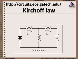
A “mesh” is one of the smallest circuit loops. For example, in
the typical circuit shown, there are 3 possible loops –
including the outer loop which includes both batteries. But
there are only 2 possible meshes and
22. Mesh Analysis
The Mesh Method is a well organized
technique which relies on KVL.
Mesh (or loop) equations are written for
every mesh in terms of the unknown
currents. Again, the method is best illustrated
by a example.
23. Example: Consider the circuit, with 2 mesh and
Find I1, I2 and I3. Assume i1, i2 are CW and i1 > i2.
let units be V, mA and kΩ
Note : Voltage polarities are assigned to all resistors, based on
the assumption made for the mesh current and Ohm’s Law
Mesh Analysis
24. A good tip is to start in the lower-left hand corner and
proceed clockwise around the mesh (loop). The first sign
encounter determine the sign for that term. And, by KVL,
the sum of all terms for each mesh equals zero.
The mesh equations are
straight-forward except for
the (i1-i2)R3 term. Both I1 and
I2 flow thru R3, but we
assumed that i1 > i2, thus the
current is i1-i2.
Note, if any of our assumptions
were wrong, we will just get
negative answers.
For mesh (1):
For mesh (2):
-3 + i1R1 + (i1-i2)R3 = 0
-(i1-i2)R3 + i2R2 - 10 = 0
Mesh Analysis
26. Q: What happens if a current source is in one
mesh?
A: The current source defines the current for
that mesh (I1 = 5A).
Mesh Analysis
27. Example: Find i1, i2. Assume i1, i2 are CW and i1 > i2.
let units be V, mA and kΩ
KVL for Mesh (1)
-9 + i1(1) + (i1-1)3 = 0
i1 + 3i1 = 9+3
4i1 = 12
i1 = 3 mA
KVL for Mesh (2)
i2 = 1 mA
Mesh Analysis
28. Quiz : Find current I3 in the circuit below,
using the Mesh Analysis Method.
-1.63 mA
+1.63 mA
-3.26mA
Mesh Analysis
30. Example: Solve for the current through the 5 ohm
resistor and the current through the 18V
source using Mesh-Current Analysis.
Mesh Analysis
31. Solution:
KVL for i1:
KVL for i2:
-18V + 5(i1-i2) + 4(i1-i3) + 1(i1) = 0
10i1- 5i2-4i3 - 18V = 0
-12 + 2i2 -5(i1 – i2) + 3(i2 - i3) = 0
KVL for i3:
-4(i1 –i3) – 3(i2 –i3) +2i3 = 0
i1 = 7.02A , i2 = 6.28A , i3 = 5.21A
The current through the 5 ohm resistor is (i1 - i2) = 0.74A
Mesh Analysis
32. Solution:
KCL for V1:
(V1-V4)/2 + (V1-V2)/3 + V1/2 = 0
Example: Solve for the current through the 5 ohm
resistor and the current through the 18V source
using Node-Voltage Analysis.
KCL for V2:
(V2-V3)/5 + V2/4 + (V2-V1)/3 = 0
KCL for V3:
(V4-V1)/2 + (V3-V2)/5 + (V5)/1 = 0
V4 - V3 = 12V
V3 - V5 = 18V
Now we have 5 equations and 5 unknowns
Mesh Analysis
33. Example: Solve for the current through the 5 ohm resistor and
the current through the 4V source using Mesh-Current Analysis.
KVL loop 2:
KVL loop 1:
i1= 5A
5(i2-i1)+10(i2-i4)+2(i2-i3) = 0
KVL loop 3:
-5i1 + 17i2 – 2i3 = 0
i3 = -2A
KVL loop 4:
10i4 + 4V + 10(I4-I2) = 0
-10i2 + 20i4 = -4
Now, we have 4 equations with 4 unknown
++
--
Mesh Analysis
34. Example: Solve for the current through the 5 ohm resistor and
the current through the 4V source using Node-Voltage Analysis.
KCL at V1:
V1 = 17.08V
V2 = 7.17V
-5A + V1/5 + (V1-V2)/10 + [V1-(V2+4)]/10 = 0
KCL at V2:
(V2-V1)/10 + V2/2 - 2A + [V2-(V1-4)]/10 = 0
Mesh Analysis
35. Example: Solve for the current through the 5 ohm resistor
and the voltage over the 3A source using Mesh-
Current Analysis.
Mesh Analysis
36. KCL at V1:
V1 = 48.625V
V2 = 33 V
V3 = 48.75V
The current through the 5 ohm resistor can be found by
Ohm's law: I = (V1 - V2)/5 = 3.125A
The voltage over the 3A source is simply V1, or 48.625V
-3A + (V1-V2)/5 + (V1-V3)/1 = 0
KCL at V2:
(V2-V1)/5 + V2/3 + (V2-V3)/2 =0
KCL at V3:
(V3-V2)/2 + (V3-V1)/1 - 8A = 0
Solution:
Mesh Analysis
37. Supermesh Analysis
Determine the values of the mesh currents, i1 and i2 for this
circuit:
(i1-i2) = 1.5 i1 = i2 + 1.5
9i1+V -12= 0 (1)
3i2 +6i2 -V= 0 (2)
Combining equations (1) and (2) gives:
9i1+ 9i2 = 12
9i1+3i2+6i2-12 = 0
9i1 + 9i2 = 12
(i1-i2) = 1.5 i1 = i2 + 1.5
i1 = 1.4167 A , i2 = -83.3 mA
Method #1 Method #2
39. Superposition
The basic concept of the
“Superposition Method” is to
analyze a circuit, one source at a
time
Using the superposition method,
we remove all the (independent)
sources, except one, and analyze
the circuit for that one.
40. Then we repeat the procedure for
another source, and so on. Finally, the
net result is founds by summing all the
single-source results. Again, the
technique is best explained with an
example
The Superposition Method us useful for
analyzing circuits with multiple power
sources.
Superposition
41. Before moving on, we need to understand the idea
of “removing” power source. Consider he typical
circuit shown – with two voltage sources:
If we were to remove one source, and still have a
complete circuit, we replace the voltage source
with a short circuit.
Superposition
42. Before moving on, we need to understand the idea
of “removing” power source. Consider he typical
circuit shown – with two voltage sources:
Similarly, if we have a circuit with two current
sources and we remove one source, but still have
complete circuit, we replace the current source
with an open circuit
Superposition
43. Reinforcing this point: to remove a
voltage a voltage source replace with a
short. To remove a current source
replace it with an open
Superposition
45. We remove the 10V source and find node voltage B
for only the 3V source.
Answer:
Superposition
Using the Node Method : I1 = I2 + I3
3 – VB VB VB
2 3 1
= +
3(3 – VB) 2VB 6VB
6 6 6
= +
9 = 11 VB
VB = 9/11 V
46. Next, we remove the 3V source and find node voltage
B for only the 10V source.
Answer:
Using the Node Method : I1 = I2 + I3
0 – VB VB – (-10) VB
2 3 1
= +
–3VB 2(VB +10) 6VB
6 6 6
= +
20 = -11 VB
VB = -20/11 V
Superposition
47. The net result is the sum of these two
calculations:
VBNET = -1 V
Which are the same results we obtained
using the Node and Mesh Methods.
i2 = 3 mA
i1 = 2 mA
i3 = -1 mA
and
Answer:
Superposition
48. Q: Does the Superposition Method only
work for computing voltages?
A: The Superposition Method work for
computing currents?
Superposition
49. Example: Find I3 using Superposition
Superposition
I3 due to 12v source only:
I3 due to 4mA source only:
I3(12v) = 12V / (1 + 2)
= 12V / 3 = 4mA
I3(4mA) = (4)(1||2) / (2)
= (4)(0.67)/2 = -1.33mA
I3(NET) = 4 – 1.33 = 2.67 mA
50. Quiz: Find current Io in the circuit below, using
the Superposition Method.
-0.84 mA
+0.84 mA
0 mA
Superposition
51. Answer: 0.84mA
Superposition
Let units be: V, mA & KΩ
For 3V source only, with 5V source removed:
RT1 = (1)(1.5)/(1 + 1.5) = 0.6 KΩ
IT = 3V / 2.6KΩ = 1.15 mA
Using the CDR,
I0(3v) = 1.15(0.6)/1 = 0.69ma ↓
52. Superposition
Answer: 0.84mA
For 5V source only, with 3V source removed:
RT2 = (1)(2)/(1 + 2) = 0.66 KΩ
IT = 5V / 2.16KΩ = 2.31 mA
Io(5v) = 2.31V(0.66)/1 = 1.53 mA ↑
So Io(net) = Io(3v) + Io(5v) = 0.69 ↓ - 1.53 ↑
Io = -8.84 ↑
53. Thevenin & Norton Circuits
The basic premise behind Thevenin and
Norton circuit analysis is that any
complex circuit can be replaced by a
simple Thevenin Equivalent or Norton
Equivalent
54. A Thevenin Equivalent circuit consists of a
single voltage source and a single series
resistor
Warning:
it is important to identify the point of view for the
equivalent circuit.
Usually it is identified by saying “at port A-B”
Thevenin & Norton Circuits
55. The Thevenin Equivalent voltage is simply the
open-circuit (no load) voltage at the port of
interest. The load resistor, if any, must be
removed
Thevenin & Norton Circuits
Using VDR:
VTH = VOC = 1V
VOC = (3V)(1Ω)/(1Ω + 2Ω)
= 1V
56. A Norton Equivalent circuit consists of a single
current source and a single parallel resistor
Warning:
it is important to identify the point of view for the
equivalent circuit.
Usually it is identified by saying “at port A-B”
Thevenin & Norton Circuits
57. The Norton Equivalent current is simply the
short-circuit current at the port of interest.
The load resistor, if any, must be removed
Thevenin & Norton Circuits
ISC = 3V/2Ω = 1.5A
IN = ISC = 1.5A
58. The Thevenin equivalent resistor equals the
Norton equivalent resistor and may be
determined in two ways:
First, RTH = RN = VOpen-Circuit / Ishort-Circuit
Thevenin & Norton Circuits
RTh = VOC/ISC = 1V/1.5A
RTh= 0.67Ω
59. Second, the Thevinin = Norton equivalent
resistance is the resistance at the port of
interest with the load resistor removed and
with all sources removed
Thevenin & Norton Circuits
RTh = 1Ω || 2 Ω
= (1)(2)/(1+2)
RTh= 0.67Ω
60. The Thevinin Equivalent circuit may then be
constructed: it consists of the Thevenin voltage
in a series with the Thevenin Resistor
Thevenin & Norton Circuits
VOC= VTh =1V
ISC= IN =1.5A
RTh = RN = 0.67Ω
61. The Norton Equivalent circuit may also be
constructed: it consists of the Norton current in
parallel with the Norton Resistor.
Thevenin & Norton Circuits
VOC= VTh =1V
ISC= IN =1.5A
RTh = RN = 0.67Ω
62. Example: In the shown circuit treat resistor R3, as the
load resistor and find the open-circuit voltage VBG.
Also find the short-circuit current IBG.
Alternatively, find RBG with both sources removed and with
R3 removed: RBG = 2kΩ // 3 kΩ = 1.2 kΩ
I = 13V / 5KΩ = 2.6 mA
I SC = 3V / 2KΩ - 10V/3KΩ
= 1.5 = 3.33 = -1.83mA
VOC = 3V – (2.6)(2)
= -2.2 V
RTH = VOC / ISC
= -2.2 V / -1.83 mA = 1.2 KΩ
Thevenin & Norton Circuits
63. The Thevenin Equivalent circuit can be drawn.
Reconnect R3 to terminal B-G and calculate
current I3 = -1mA
Thevenin & Norton Circuits
Thevenin Equivalent
VTH = VOC = -2.2V
RTH = 1.20KΩ
I3 = -2.2V / (1.2 + 1.0KΩ) = -1.0 mA
64. Likewise, The Norton Equivalent circuit can be drawn.
R3 is then reconnected to the terminal B-G and I3 is
determined using the CDR : I3 = -1mA
The Thevenin and Norton Equivalent circuit produce
the same answer for I3 as the other methods.
Thevenin & Norton Circuits
ISC = -183mA
RN = RTH = 1.20KΩ
RT = (1.2)(1)/(1 + 1.20) = 1.20/2.20 = .55KΩ
I3 = -(1.83)(.55KΩ)/1KΩ = -1.0 mA
Norton Equivalent
65. Thevenin & Norton Circuits
There is another reason for finding the Thevenin or Norton
Equivalent of a complex circuit
IT can be shown (but we will not) that the maximum power
a circuit can deliver to a load resistor is when the load
resistor equals the source resistor.
Or, the maximum power output occurs when the load
resistor equals the Thevenin resistance.
RL = RTH for Maximum Output Power
For this example, the maximum
power that can be delivered to RL
is when
RL = RTH = 1.2KΩ
or
ROUT MAX = I2 RL = (0.92)2 x 1.2 = 1.0 mW
66. Q: IS it easy to convert a Thevenin Equivalent
circuit to a Norton Equivalent circuit?
A: Yes, just use Ohm’s Law.
Thevenin & Norton Circuits
RTh = RN
IN= VTh /RTh
68. Quiz: Convert the Thevenin circuit below to a Norton
equivalent circuit. How much is the maximum
power the circuit can supply to load resistor RL
IN = 9A, RN = 9Ω & Pmax = 27W
IN = 6A, RN = 6Ω & Pmax = 54W
IN = 4A, RN = 3Ω & Pmax = 12W
Thevenin & Norton Circuits
70. Example: for the circuit in figure. It is given that R1=20K,
R2=1K, and A1=50. Solve for the Thevenin and
Norton equivalent circuits seen looking into the
output terminals
Thevenin & Norton Circuits
73. Example: Find the Thévenin equivalent with respect
to the 7k ohm resistor.
Thevenin & Norton Circuits
74. Solution:
Remove the 7KΩ, since it is not part of the circuit we
wish to simplify.
Find VTH, the voltage across the terminals (voltage
across the 3k ohm).
1k and 2k are parallel.
1k || 2k = (1k*2k) / (1k+2k) = 2M/3k = 2/3k = 667Ω
Now use VDR to compute VTH across the 3k ohm.
VTH = [3k/(667+3k)] * 5V = 4.1V
Find the Thevenin Resistance by
remove all sources and computing the
total resistance across the terminals.
The voltage sources is shorted.
Rth = 1k||2k||3k = 545 ohms
The final Thevenin equivalent is then:
Thevenin & Norton Circuits
75. Example: Find the Norton Equivalent with respect to
the 3K resistor in the middle of the circuit,
i.e., the 3K resistor itself should not be part
of the equivalent that you compute.
Thevenin & Norton Circuits
76. Solution:
• To find the Norton with respect to the 3K, we remove the 3K out of the
circuit
• The circuit to the left of the 3K is already a Norton equivalent, where the
Norton current is -10 mA (because it is facing down). The resistance is
infinite. That is, when you open the current source to deactivate it, the
1K and 2K are left disconnected.
• The circuit to the right of the 3K is already a Thevenin, where the voltage
is 6V and the equivalent resistance is 9K. Converting to a Norton, we get
Norton current of 0.667 mA and a resistance of 9K.
• Now combine the two Nortons. The total current will be:
-10mA + 0.667mA = -9.33 mA.
• The total resistance is infinite in parallel with 9K, which is simply 9K.
Thevenin & Norton Circuits
77. Example: The circuit shown right is the Thevenin
equivalent circuit of the circuit shown
left. Find the value of the open circuit
voltage, Voc and Thevenin resistance, Rth.
Thevenin & Norton Circuits
79. Example: The circuit shown in Figure is the Thevenin
equivalent circuit of the circuit shown in
Figure. Find the value of the open circuit
voltage, Voc and Thevenin resistance, Rth.
Thevenin & Norton Circuits