SlideShare ist ein Scribd-Unternehmen logo
1 von 12
Downloaden Sie, um offline zu lesen
Chapter 2
Assembly
Programming I
The assembly language is a low-level programming language that is particularly useful for
Embedded Systems and Hardware Device Drivers. The Embedded Systems have fewer resources
than PCs and mainframes. Assembly programming can be useful for optimizing code for speed or
size in small embedded systems, the statements correspond directly to clock cycles and enables
easier hardware-specific task. The control of Machine Code is better than a high level language, but
the programmer must know the architecture for an exact microcontroller before he can write
effective code. It’s necessary to consider that development time is longer.
Assembly Programming………………….…………….…….………. 1
Memory Organization…..…………..………………….……………. 1
Data Memory (RAM).………………………….……………….……. 1
Program Memory (Flash/EE)……………….……………………...…. 3
Extended Data Memory (XRAM)………………………………………. 4
Data Memory (Flash/EE).……………..………………………..……. 4
Addressing Modes.……………..………………………..…………. 6
Interrupts.……………..……………...……………………..…… 6
Triggering an Interrupt by Software.……….……..…………….……. 8
Stack pointers and Interrupts.…………….……..…………….……. 8
Reset Interrupt.……….……..……………………………….…….9
Checklist for Interrupt Programs.……….……………………..………9
Example Program.………..…..……………………………….…….9
Reset Value of Stack Pointer (07H)
Memory Organization
Data Memory (RAM)
Memory Function
7FH
30H
General Purpose
(Direct or Indirect
Addressing)
2FH
.
20H
7FH
Bit Addressable Area
00H
1FH
.
18H
Register Bank 3
PSW
x x x 1 1 x x x
17H
.
10H
Register Bank 2
PSW
x x x 1 0 x x x
0FH
.
08H
Register Bank 1
PSW
x x x 0 1 x x x
07H
.
00H
Register Bank 0
PSW
x x x 0 0 x x x
Assembly Programming
The MicroConverter® series of Analog Devices
contains four different memory blocks:
✓ Data Memory (RAM): 256 x 8
✓ Extended Data Memory (XRAM): 2K x 8
✓ Program Memory (Flash/EE): 62K x 8
✓ Data Memory (Flash/EE): 4K x 8
256 bytes
2k bytes
4k bytes
62k bytes
RAM
Flash/EE
(Data)
XRAM
Flash/EE
(Program)
1
The general-purpose RAM is divided into two separate memories, the upper and the lower 128 bytes of RAM. The
lower 128 bytes of RAM can be accessed through direct or indirect addressing. The upper 128 bytes of RAM can
only be accessed through indirect addressing because it shares the same address space as the SFR space, which
can only be accessed through direct addressing.
Lower 128 bytes: The lowest 32 bytes are grouped into four banks of eight registers addressed as R0 through R7.
The next 16 bytes (128 bits), form a block of bit addressable memory space (00H – 7FH). The last block (30H-7FH)
is for general purpose.
After Reset, the SP register contains value 07H. As we push data onto the stack, the SP is incremented.
It’s a good programming technic change the SP value to higher memory space (e.g. 70H), avoiding the lost of the
Register Bank 1. The Register Bank is selected using PSW (Program Status Word)
CY (PSW.7) Carry Flag. This flag is set whenever there is a carry out from the D7 bit. Affected after an 8-bit addition
or subtraction.
AC (PSW.6) Auxiliary Carry Flag. Set when there is a carry from D3 to D4 during an addition or subtraction operation.
F0 (PSW.5) General Purpose Flag.
RS1 (PSW.4) Register Bank Selector Bit 1.
RS0 (PSW.3) Register Bank Selector Bit 0.
OV (PSW.2) Overflow Flag. This flag is set whenever the result of a signed number operation is too large.
F1 (PSW.1) General Purpose Flag.
P (PSW.0) Parity Flag. If the A register contains an odd number of 1s, then P = 1. Therefore, P = 0 if A has an even
number of 1s.
CY AC F0 RS1 RS0 OV F1 P
Assembly Programming
2
Program Memory (Flash/EE)
Program Memory is used for permanent saving program (Machine Code). Flash/EE memory combines the flexible
in-circuit reprogrammable features of EEPROM with the space efficient/ density features of EPROM which is based
on a single transistor cell architecture. Depending on the settings made in compiler, program memory may also
used to store a constant variables. After Reset, the Microconverter begins execution from address 0000H. The
following program test PSW Register. The resulting Machine Code in program memory is shown below
Assembly Programming
The above program tests the Data Memory (RAM), using indirect, direct and bit addressing , the value of the
memory locations are shown below
3
The internal XRAM (2K x 8) can be used as an extension of RAM (only 256 x 8). By default, this memory is not active.
The XRAM can be enable using CFG832 register (MOV CFG832, #01H). The transfer with XRAM Memory is
implemented using MOVX instructions. An example of use of this memory is shows below
The 4 kBytes of Flash/EE data memory are configured as 1024 pages, each of 4 bytes. A group of four data registers
(EDATA1–4) is used to hold the four bytes of data at each page. The page is addressed via the two registers, EADRH
and EADRL as is shows in the table
The ECON register is an 8-bit control register that may be written with one of nine Flash/EE memory access
commands to trigger various read, write, erase, and verify functions.
Extended Data Memory (XRAM)
Data Memory (Flash/EE)
Page Address (EADRH/L) EDATA 1 EDATA 2 EDATA 3 EDATA 4
3FFH Byte 1 ( 0FFCH) Byte 2 ( 0FFDH) Byte 3 ( 0FFEH) Byte 4 ( 0FFFH)
.. .. .. .. ..
001H Byte 1 ( 0004H) Byte 2 ( 0005H) Byte 3 ( 0006H) Byte 4 ( 0007H)
000H Byte 1 ( 0000H) Byte 2 ( 0001H) Byte 3 ( 0002H) Byte 4 ( 0003H)
Assembly Programming
4
The core cannot respond to interrupt requests until the Flash/EE operation is complete, some operations like
ERASE command, can delay until 2 msec.
Assembly Programming
5
The Vector Address represents the address of the interrupt service routine. The Interrupt Bit represents the bits
that are “set” when the equivalent interrupt is requested. We can cause an interrupt with an instruction that
“set” the interrupt flag. The Priority Level control the order in which multiple interrupts will be serviced.
In case of multiple interrupts, the following rules apply:
✓ While a low priority interrupt handler is running, if a high priority interrupt arrives, the handler will be
interrupted, and the high priority handler will run (interrupt inside interrupt).
✓ If a high priority interrupt is running, it cannot be interrupted by any other.
✓ A low-priority interrupt handler will be invoked only if no other interrupt is already executing.
✓ If two interrupts occur at the same time, the interrupt with higher priority will execute first. If both
interrupts are of the same priority, the interrupt which is higher in polling sequence will be executed
first.
Addressing Modes
Addressing Mode Assembler Instruction Example Description
Immediate MOV A, #data MOV A, #30H Transfers an 8-bit data immediately
Direct MOV A, direct MOV A, 30H 30H is the address where the operand is stored
Register Direct MOV A, Rn MOV A, R5 Registers can take value from R0,R1…to R7
Register Indirect MOV A, @Ri MOV A, @R0 R0, R1 has the address where the operand is stored
Indexed MOVC A, @A+DPTR MOVC A, @A+DPTR The source operand is @A+DPTR
Interrupts
Int. Number Interrupt Name Vector Address Interrupt Bit Priority Level
0 External Hardware (INT0) 03H IE0 3
1 Timer/Counter 0 overflow 0BH TF0 5
2 External Hardware (INT1) 13H IE1 6
3 Timer/Counter 1 overflow 1BH TF1 7
4 UART 23H RI/TI 9
5 Timer/Counter 2 overflow 2BH TF2/EXF2 10
6 End of ADC Conversion 33H ADCI 4
7 SPI/I2C 3BH ISPI/I2CI 8
8 Power Supply Monitor 43H PSMCON.5 1
9 Time Interval Counter 53H TIMECON.2 11
10 Watchdog timer 5BH WDS 2
Addressing mode is a way to address an operand. It can be a direct address of memory, register, numerical data etc.
Assembly Programming
A single microcontroller can serve several devices. There are two ways to do that: Interrupt or Polling. In the
Interrupt method, whenever any device needs its service, the device notifies the microcontroller by sending it an
interrupt signal. Upon receiving an interrupt signal, the microcontroller interrupts whatever it is doing and serves
the device. The program associated with the interrupt is called the Service Interrupt Routine (ISR). In Polling, the
microcontroller continuously monitors the status of a given device; when the status condition is met, it performs
the service. After that, it moves on to monitor the next device until each one is serviced. The advantage of
interrupts is that the microcontroller can serve many devices (not all at the same time, of course); each device
can get the attention of the microcontroller based on the priority assigned to it. The most important reason that
the interrupt method is preferable is that the polling method wastes much of the microcontroller’s time by polling
devices that do not need service. The following table shows the typical interrupts in Microconverters based on
8052 core
6
The following program shows how an External Interrupt 0 is attended
Assembly Programming
There are three interrupt-related Special Function Registers. IE (Interrupt Enable):
EA (IE.7). Enable all interrupt sources (1 = enable; 0 = disable)
EADC (IE.6). ADC Interrupt (1 = enable; 0 = disable)
ET2 (IE.5). Timer 2 interrupt (1 = enable; 0 = disable)
ES (IE.4). UART serial port interrupt (1 = enable; 0 = disable)
ET1 (IE.3). Timer 1 interrupt (1 = enable; 0 = disable)
EX1 (IE.2). External Interrupt 1 (1 = enable; 0 = disable)
ET0 (IE.1). Timer 0 interrupt (1 = enable; 0 = disable)
EX0 (IE.0). External Interrupt 0 (1 = enable; 0 = disable)
IP (Interrupt Priority):
RESERVED (IP.7). Reserved for future use
PADC (IP.6). ADC interrupt priority (1 = high; 0 = low)
PT2 (IP.5). Timer 2 interrupt priority (1 = high; 0 = low)
PS (IP.4). UART serial port interrupt priority (1 = high; 0 = low)
PT1 (IP.3). Timer 1 interrupt priority (1 = high; 0 = low)
PX1 (IP.2). External Interrupt 1 priority (1 = high; 0 = low)
PT0 (IP.1). Timer 0 interrupt priority (1 = high; 0 = low)
PX0 (IP.0). External Interrupt 0 (1 = enable; 0 = disable)
IEIP2 (SECONDARY INTERRUPT ENABLE REGISTER, No Bit Addressable)
RESERVED. Reserved for future use
PTI. Priority for time interval interrupt
PPSM. Priority for power supply monitor interrupt
PSI. Priority for SPI/I2C interrupt
RESERVED. This bit must contain 0
ETI. Enable interval counter interrupt (1 = enable; 0 = disable)
EPSMI. Enable power supply monitor interrupt (1 = enable; 0 = disable)
ESI. Enable SPI or I2C serial port interrupt (1 = enable; 0 = disable)
7
The program is stored in memory as shows bellow
The interrupt program of the above section is executed by falling edge on P3.2. The same occur when you set IE0
(SETB IE0). Set the equivalent interrupt bit is equivalent to generate an interrupt by software.
A stack operates in a last-in/first-out sense. When a new data item is entered onto the top of a stack (push), the stack
pointer increments to the next physical memory address, and the new item is copied to that address. When a data
item is pulled (pop) from the top of a stack, the item is copied from the address of the SP, and the SP decrements to
the next available item at the top of the stack. The most general types of stack-specific instructions are: PUSH (put
data onto the stack), POP (“remove” data from the stack), CALL (jump to a subroutine), RETURN (return from a
subroutine) and INTERRUP.
Triggering an Interrupt by Software
Stack Pointer and Interrupts
Assembly Programming
After RESET, the Program Counter (PC) has the value
0000H, where the Microconveter take the Operation
Code (OC) of the first instruction to be executed (JMP).
Address
ROM
Instruction Machine
code
PC
0000H JMP 000AH 02H (OC) 0000H
0001H 00H 0000H
0002H 0AH 000AH
. . . .
000AH SETB IT0 D2H (OC) 000AH
000BH 88H 000CH
000CH SETB EX0 D2H (OC) 000CH
000DH A8H 000EH
000EH SETB EA D2H (OC) 000EH
000FH AFH 0010H
0010H SETB P2.5 D2H (OC) 0010H
0011H A5H 0012H
0012H MOV
PCON,#22H
75H (OC) 0012H
0013H 87H 0015H
0014H 22H 0015H
0015H NOP 00H 0015H
0016H NOP 00H 0016H
1 1
The PC takes the value of the address where the OC
of the next instruction is stored.
2
2
3
The program Stop the Execution, waiting for an External
Interrupt 0.
The PC has the value of the address where the OC of
the next instruction is stored (0015H).
3
4
4
Address RAM Value
07H (SP)
08H (SP+1) 15 (PC, LS Byte)
09H (SP+2) 00 (PC, MS Byte)
The external interrupt 0 is activated with the falling
edge on P3.2. IE0 of TCON goes high. The Stack
Pointer (SP) is increased, and the PC is stored on Stack
(Least significant byte first).
5
5
Address
ROM
Instruction Machine
code
PC
0003H CLR P2.5 C2H (OC) 0003H
0004H A5H 0005H
0005H RETI 32 (OC) 0005H
The PC is initialized with the 0003H address ( INT0
Interrupt address of the ISR from the interrupt vector
table of). It starts to execute the interrupt service.
subroutine
6
6
7
The interrupt routine is executed until RETI instruction,
which clear IE0 of TCON, indicating that the servicing of
the interrupt is over. Get pop PC (0015H) from Stack,
decreasing SP 2 times and tacking its original value (07H)
7
8
8
The Microconverter continues the execution of the
program that was interrupted
8
✓ Vector Address: Address of the Interrupt Service Routine (ISR). Place ISR, which is terminated by RETI instruction.
✓ Unconditional jump to anywhere in program memory: There are only 8 bytes between ISR Addresses.
✓ Redefine the value of the Stack: You must ensure that there is sufficient RAM capacity in the STACK to handle
all interrupts, PUSH instructions to save registers and CALL to subroutines.
Redefine the Stack avoid the loss of Register Bank 1.
✓ Protect your registers: An interrupt must leave the processor in the same state as it was in when the interrupt
initiated. In general, your interrupt routine must protect the following registers:
• PSW
• DPTR (DPH/DPL)
• PSW
• ACC
• B
• Registers R0-R7
✓ Pop the same number of values off the stack as you pushed onto it, take care of the order (last in/first out).
✓ Prioritize interrupts properly.
✓ Keep ISR short, use flags.
✓ The interrupts must be enable by software. Enable the global interrupt control bit.
✓ External interrupts: Level or Edge triggered.
Reset Interrupt
Checklist for Interrupt Programs
Example program
Assembly Programming
Assembly ProgrammingRESET is the highest priority interrupt. A high level on RESET pin for 24 master clock cycles while the oscillator is
running resets the device. As result PC = 0000H, where must be defined the OC of the first instruction to be executed.
RESET can be executed by software, using following program
9
1
1 Vector Address (INT0)
2
2 Stack redefinition
3
3 Interrupt priority
4
4 New address for ISR
5 5External interrupt: Falling edge
66 Interrupt enable
Assembly Programming
10
4
7 Used registers are saved
7
8
8 Used registers are restored: Inverse order (last in/first out)

Weitere ähnliche Inhalte

Was ist angesagt?

Bao cao nhap mon dien tu vien thong
Bao cao nhap mon dien tu vien thongBao cao nhap mon dien tu vien thong
Bao cao nhap mon dien tu vien thongshockwavetn94
 
(Led nháy theo nhạc) báo cáo đồ án điện tử viễn thông 1
(Led nháy theo nhạc) báo cáo đồ án điện tử   viễn thông 1(Led nháy theo nhạc) báo cáo đồ án điện tử   viễn thông 1
(Led nháy theo nhạc) báo cáo đồ án điện tử viễn thông 1Huy Tuong
 
LUẬN VĂN THIẾT KẾ HỆ THỐNG NHÚNG VỚI VI ĐIỀU KHIỂN LÕI MỀM VÀ HỆ ĐIỀU HÀNH TR...
LUẬN VĂN THIẾT KẾ HỆ THỐNG NHÚNG VỚI VI ĐIỀU KHIỂN LÕI MỀM VÀ HỆ ĐIỀU HÀNH TR...LUẬN VĂN THIẾT KẾ HỆ THỐNG NHÚNG VỚI VI ĐIỀU KHIỂN LÕI MỀM VÀ HỆ ĐIỀU HÀNH TR...
LUẬN VĂN THIẾT KẾ HỆ THỐNG NHÚNG VỚI VI ĐIỀU KHIỂN LÕI MỀM VÀ HỆ ĐIỀU HÀNH TR...KhoTi1
 
Tài liệu tham khảo trường điện từ
Tài liệu tham khảo trường điện từTài liệu tham khảo trường điện từ
Tài liệu tham khảo trường điện từCửa Hàng Vật Tư
 
Bài giảng kiến trúc máy tính
Bài giảng kiến trúc máy tínhBài giảng kiến trúc máy tính
Bài giảng kiến trúc máy tínhCao Toa
 
Bài Tập Xử Lí Tín Hiệu Số
Bài Tập Xử Lí Tín Hiệu SốBài Tập Xử Lí Tín Hiệu Số
Bài Tập Xử Lí Tín Hiệu Sốviethung094
 
Notes: Verilog Part 1 - Overview - Hierarchical Modeling Concepts - Basics
Notes: Verilog Part 1 - Overview - Hierarchical Modeling Concepts - BasicsNotes: Verilog Part 1 - Overview - Hierarchical Modeling Concepts - Basics
Notes: Verilog Part 1 - Overview - Hierarchical Modeling Concepts - BasicsJay Baxi
 
Mạch led nháy theo nhạc sử dụng IC AN6884
Mạch led nháy theo nhạc sử dụng IC AN6884Mạch led nháy theo nhạc sử dụng IC AN6884
Mạch led nháy theo nhạc sử dụng IC AN6884Linh Hoang-Tuan
 
Digital VLSI Design and FPGA Implementation
Digital VLSI Design and FPGA ImplementationDigital VLSI Design and FPGA Implementation
Digital VLSI Design and FPGA ImplementationAmber Bhaumik
 
Chuong02
Chuong02Chuong02
Chuong02na
 
8051 assembly programming
8051 assembly programming8051 assembly programming
8051 assembly programmingsergeiseq
 
Các toán tử trong c
Các toán tử trong cCác toán tử trong c
Các toán tử trong cIam Me
 
Digital Systems Design
Digital Systems DesignDigital Systems Design
Digital Systems DesignReza Sameni
 

Was ist angesagt? (20)

Bao cao nhap mon dien tu vien thong
Bao cao nhap mon dien tu vien thongBao cao nhap mon dien tu vien thong
Bao cao nhap mon dien tu vien thong
 
(Led nháy theo nhạc) báo cáo đồ án điện tử viễn thông 1
(Led nháy theo nhạc) báo cáo đồ án điện tử   viễn thông 1(Led nháy theo nhạc) báo cáo đồ án điện tử   viễn thông 1
(Led nháy theo nhạc) báo cáo đồ án điện tử viễn thông 1
 
LUẬN VĂN THIẾT KẾ HỆ THỐNG NHÚNG VỚI VI ĐIỀU KHIỂN LÕI MỀM VÀ HỆ ĐIỀU HÀNH TR...
LUẬN VĂN THIẾT KẾ HỆ THỐNG NHÚNG VỚI VI ĐIỀU KHIỂN LÕI MỀM VÀ HỆ ĐIỀU HÀNH TR...LUẬN VĂN THIẾT KẾ HỆ THỐNG NHÚNG VỚI VI ĐIỀU KHIỂN LÕI MỀM VÀ HỆ ĐIỀU HÀNH TR...
LUẬN VĂN THIẾT KẾ HỆ THỐNG NHÚNG VỚI VI ĐIỀU KHIỂN LÕI MỀM VÀ HỆ ĐIỀU HÀNH TR...
 
Đề tài: Thiết kế, chế tạo và điều khiển robot xe đua dò line, HAY
Đề tài: Thiết kế, chế tạo và điều khiển robot xe đua dò line, HAYĐề tài: Thiết kế, chế tạo và điều khiển robot xe đua dò line, HAY
Đề tài: Thiết kế, chế tạo và điều khiển robot xe đua dò line, HAY
 
Chuong2 cấu trúc phần cứng 8051
Chuong2 cấu trúc phần cứng 8051Chuong2 cấu trúc phần cứng 8051
Chuong2 cấu trúc phần cứng 8051
 
Tài liệu tham khảo trường điện từ
Tài liệu tham khảo trường điện từTài liệu tham khảo trường điện từ
Tài liệu tham khảo trường điện từ
 
Bài giảng kiến trúc máy tính
Bài giảng kiến trúc máy tínhBài giảng kiến trúc máy tính
Bài giảng kiến trúc máy tính
 
Bài Tập Xử Lí Tín Hiệu Số
Bài Tập Xử Lí Tín Hiệu SốBài Tập Xử Lí Tín Hiệu Số
Bài Tập Xử Lí Tín Hiệu Số
 
ĐỒ ÁN: Thiết kế mạch đếm sản phẩm dùng cảm biến hồng ngoại!
ĐỒ ÁN: Thiết kế mạch đếm sản phẩm dùng cảm biến hồng ngoại!ĐỒ ÁN: Thiết kế mạch đếm sản phẩm dùng cảm biến hồng ngoại!
ĐỒ ÁN: Thiết kế mạch đếm sản phẩm dùng cảm biến hồng ngoại!
 
Notes: Verilog Part 1 - Overview - Hierarchical Modeling Concepts - Basics
Notes: Verilog Part 1 - Overview - Hierarchical Modeling Concepts - BasicsNotes: Verilog Part 1 - Overview - Hierarchical Modeling Concepts - Basics
Notes: Verilog Part 1 - Overview - Hierarchical Modeling Concepts - Basics
 
Mạch led nháy theo nhạc sử dụng IC AN6884
Mạch led nháy theo nhạc sử dụng IC AN6884Mạch led nháy theo nhạc sử dụng IC AN6884
Mạch led nháy theo nhạc sử dụng IC AN6884
 
Read & write
Read & writeRead & write
Read & write
 
Digital VLSI Design and FPGA Implementation
Digital VLSI Design and FPGA ImplementationDigital VLSI Design and FPGA Implementation
Digital VLSI Design and FPGA Implementation
 
Chuong02
Chuong02Chuong02
Chuong02
 
Ktmt chuong 5
Ktmt chuong 5Ktmt chuong 5
Ktmt chuong 5
 
8051 assembly programming
8051 assembly programming8051 assembly programming
8051 assembly programming
 
Đề tài: Xây dựng và điều khiển động cơ BLDC xe đạp điện, HAY
Đề tài: Xây dựng và điều khiển động cơ BLDC xe đạp điện, HAYĐề tài: Xây dựng và điều khiển động cơ BLDC xe đạp điện, HAY
Đề tài: Xây dựng và điều khiển động cơ BLDC xe đạp điện, HAY
 
Các toán tử trong c
Các toán tử trong cCác toán tử trong c
Các toán tử trong c
 
Digital Systems Design
Digital Systems DesignDigital Systems Design
Digital Systems Design
 
Bien doi lapalce
Bien doi lapalceBien doi lapalce
Bien doi lapalce
 

Ähnlich wie Assembly programming

The hardware of the Mcs 51 microcontroller
 The hardware of the Mcs 51 microcontroller The hardware of the Mcs 51 microcontroller
The hardware of the Mcs 51 microcontrollerGarba Geidam
 
Microprocessor and microcontroller
Microprocessor and microcontrollerMicroprocessor and microcontroller
Microprocessor and microcontrollerRavinder Singla
 
An Overview of LPC2101/02/03
An Overview of LPC2101/02/03An Overview of LPC2101/02/03
An Overview of LPC2101/02/03Premier Farnell
 
Overview of LPC213x MCUs
Overview of LPC213x MCUsOverview of LPC213x MCUs
Overview of LPC213x MCUsPremier Farnell
 
Features of tms_320_2nd_generation_dsp
Features of tms_320_2nd_generation_dspFeatures of tms_320_2nd_generation_dsp
Features of tms_320_2nd_generation_dspSmriti Tikoo
 
Overview of LPC214x MCUs
Overview of LPC214x MCUsOverview of LPC214x MCUs
Overview of LPC214x MCUsPremier Farnell
 
A 32-Bit Parameterized Leon-3 Processor with Custom Peripheral Integration
A 32-Bit Parameterized Leon-3 Processor with Custom Peripheral IntegrationA 32-Bit Parameterized Leon-3 Processor with Custom Peripheral Integration
A 32-Bit Parameterized Leon-3 Processor with Custom Peripheral IntegrationTalal Khaliq
 
Microprocessors and microcontrollers
Microprocessors and microcontrollersMicroprocessors and microcontrollers
Microprocessors and microcontrollersgomathy S
 
Direct Memory Access & Interrrupts
Direct Memory Access & InterrruptsDirect Memory Access & Interrrupts
Direct Memory Access & InterrruptsSharmilaChidaravalli
 
8051 Architecture and PIN Configuration.pdf
8051 Architecture and PIN Configuration.pdf8051 Architecture and PIN Configuration.pdf
8051 Architecture and PIN Configuration.pdfSrikrishna Thota
 
Ec 1303 microprocessor_its_applications
Ec 1303 microprocessor_its_applicationsEc 1303 microprocessor_its_applications
Ec 1303 microprocessor_its_applicationsMerin Jesuraj
 

Ähnlich wie Assembly programming (20)

assignment 1-MC.pdf
assignment 1-MC.pdfassignment 1-MC.pdf
assignment 1-MC.pdf
 
x86_1.ppt
x86_1.pptx86_1.ppt
x86_1.ppt
 
002079
002079002079
002079
 
The hardware of the Mcs 51 microcontroller
 The hardware of the Mcs 51 microcontroller The hardware of the Mcs 51 microcontroller
The hardware of the Mcs 51 microcontroller
 
Microprocessor and microcontroller
Microprocessor and microcontrollerMicroprocessor and microcontroller
Microprocessor and microcontroller
 
An Overview of LPC2101/02/03
An Overview of LPC2101/02/03An Overview of LPC2101/02/03
An Overview of LPC2101/02/03
 
Overview of LPC213x MCUs
Overview of LPC213x MCUsOverview of LPC213x MCUs
Overview of LPC213x MCUs
 
Features of tms_320_2nd_generation_dsp
Features of tms_320_2nd_generation_dspFeatures of tms_320_2nd_generation_dsp
Features of tms_320_2nd_generation_dsp
 
8086
80868086
8086
 
Important questions
Important questionsImportant questions
Important questions
 
Embedded system classes in mumbai
Embedded system classes in mumbaiEmbedded system classes in mumbai
Embedded system classes in mumbai
 
Overview of LPC214x MCUs
Overview of LPC214x MCUsOverview of LPC214x MCUs
Overview of LPC214x MCUs
 
A 32-Bit Parameterized Leon-3 Processor with Custom Peripheral Integration
A 32-Bit Parameterized Leon-3 Processor with Custom Peripheral IntegrationA 32-Bit Parameterized Leon-3 Processor with Custom Peripheral Integration
A 32-Bit Parameterized Leon-3 Processor with Custom Peripheral Integration
 
Microprocessors and microcontrollers
Microprocessors and microcontrollersMicroprocessors and microcontrollers
Microprocessors and microcontrollers
 
Pic full note
Pic full notePic full note
Pic full note
 
Direct Memory Access & Interrrupts
Direct Memory Access & InterrruptsDirect Memory Access & Interrrupts
Direct Memory Access & Interrrupts
 
unit-2.pptx
unit-2.pptxunit-2.pptx
unit-2.pptx
 
486 or 80486 DX Architecture
486 or 80486 DX Architecture486 or 80486 DX Architecture
486 or 80486 DX Architecture
 
8051 Architecture and PIN Configuration.pdf
8051 Architecture and PIN Configuration.pdf8051 Architecture and PIN Configuration.pdf
8051 Architecture and PIN Configuration.pdf
 
Ec 1303 microprocessor_its_applications
Ec 1303 microprocessor_its_applicationsEc 1303 microprocessor_its_applications
Ec 1303 microprocessor_its_applications
 

Mehr von Omar Sanchez

Assembly programming II
Assembly programming IIAssembly programming II
Assembly programming IIOmar Sanchez
 
Assembler Programming
Assembler ProgrammingAssembler Programming
Assembler ProgrammingOmar Sanchez
 
Functions for Nano 5 Card
Functions for Nano 5 CardFunctions for Nano 5 Card
Functions for Nano 5 CardOmar Sanchez
 
Ejemplos de modelos basados en adaptacion parametrica
Ejemplos de modelos basados en adaptacion parametricaEjemplos de modelos basados en adaptacion parametrica
Ejemplos de modelos basados en adaptacion parametricaOmar Sanchez
 
Sistemas numericos
Sistemas numericosSistemas numericos
Sistemas numericosOmar Sanchez
 
Referencias MATLAB
Referencias MATLABReferencias MATLAB
Referencias MATLABOmar Sanchez
 
Control Modelo de Referencia y Linealizacion po Realimentacion
Control Modelo de Referencia y Linealizacion po RealimentacionControl Modelo de Referencia y Linealizacion po Realimentacion
Control Modelo de Referencia y Linealizacion po RealimentacionOmar Sanchez
 
Segmentación de imagenes
Segmentación de imagenesSegmentación de imagenes
Segmentación de imagenesOmar Sanchez
 
Imagen e histograma
Imagen e histogramaImagen e histograma
Imagen e histogramaOmar Sanchez
 
Funciones de Lyapunov basado en Krasovskii
Funciones de Lyapunov basado en KrasovskiiFunciones de Lyapunov basado en Krasovskii
Funciones de Lyapunov basado en KrasovskiiOmar Sanchez
 
Sensores de robots
Sensores de robotsSensores de robots
Sensores de robotsOmar Sanchez
 
Vehiculos no tripulados
Vehiculos no tripuladosVehiculos no tripulados
Vehiculos no tripuladosOmar Sanchez
 
Algunos aspectos de estabilidad
Algunos aspectos de estabilidadAlgunos aspectos de estabilidad
Algunos aspectos de estabilidadOmar Sanchez
 
Control basado en modelo
Control basado en modeloControl basado en modelo
Control basado en modeloOmar Sanchez
 

Mehr von Omar Sanchez (20)

Assembler4
Assembler4Assembler4
Assembler4
 
Assembly programming II
Assembly programming IIAssembly programming II
Assembly programming II
 
Assembler Programming
Assembler ProgrammingAssembler Programming
Assembler Programming
 
Functions for Nano 5 Card
Functions for Nano 5 CardFunctions for Nano 5 Card
Functions for Nano 5 Card
 
Ejemplos de modelos basados en adaptacion parametrica
Ejemplos de modelos basados en adaptacion parametricaEjemplos de modelos basados en adaptacion parametrica
Ejemplos de modelos basados en adaptacion parametrica
 
Sistemas numericos
Sistemas numericosSistemas numericos
Sistemas numericos
 
Ensamblador
EnsambladorEnsamblador
Ensamblador
 
Nano5 features
Nano5 featuresNano5 features
Nano5 features
 
Referencias MATLAB
Referencias MATLABReferencias MATLAB
Referencias MATLAB
 
Control Modelo de Referencia y Linealizacion po Realimentacion
Control Modelo de Referencia y Linealizacion po RealimentacionControl Modelo de Referencia y Linealizacion po Realimentacion
Control Modelo de Referencia y Linealizacion po Realimentacion
 
Fundposori
FundposoriFundposori
Fundposori
 
Segmentación de imagenes
Segmentación de imagenesSegmentación de imagenes
Segmentación de imagenes
 
Imagen e histograma
Imagen e histogramaImagen e histograma
Imagen e histograma
 
Funciones de Lyapunov basado en Krasovskii
Funciones de Lyapunov basado en KrasovskiiFunciones de Lyapunov basado en Krasovskii
Funciones de Lyapunov basado en Krasovskii
 
Sensores de robots
Sensores de robotsSensores de robots
Sensores de robots
 
Vehiculos no tripulados
Vehiculos no tripuladosVehiculos no tripulados
Vehiculos no tripulados
 
Algunos aspectos de estabilidad
Algunos aspectos de estabilidadAlgunos aspectos de estabilidad
Algunos aspectos de estabilidad
 
Control basado en modelo
Control basado en modeloControl basado en modelo
Control basado en modelo
 
Grupos próximos
Grupos próximosGrupos próximos
Grupos próximos
 
Redes Neuronales
Redes NeuronalesRedes Neuronales
Redes Neuronales
 

Kürzlich hochgeladen

Histor y of HAM Radio presentation slide
Histor y of HAM Radio presentation slideHistor y of HAM Radio presentation slide
Histor y of HAM Radio presentation slidevu2urc
 
04-2024-HHUG-Sales-and-Marketing-Alignment.pptx
04-2024-HHUG-Sales-and-Marketing-Alignment.pptx04-2024-HHUG-Sales-and-Marketing-Alignment.pptx
04-2024-HHUG-Sales-and-Marketing-Alignment.pptxHampshireHUG
 
08448380779 Call Girls In Civil Lines Women Seeking Men
08448380779 Call Girls In Civil Lines Women Seeking Men08448380779 Call Girls In Civil Lines Women Seeking Men
08448380779 Call Girls In Civil Lines Women Seeking MenDelhi Call girls
 
Evaluating the top large language models.pdf
Evaluating the top large language models.pdfEvaluating the top large language models.pdf
Evaluating the top large language models.pdfChristopherTHyatt
 
Raspberry Pi 5: Challenges and Solutions in Bringing up an OpenGL/Vulkan Driv...
Raspberry Pi 5: Challenges and Solutions in Bringing up an OpenGL/Vulkan Driv...Raspberry Pi 5: Challenges and Solutions in Bringing up an OpenGL/Vulkan Driv...
Raspberry Pi 5: Challenges and Solutions in Bringing up an OpenGL/Vulkan Driv...Igalia
 
How to Troubleshoot Apps for the Modern Connected Worker
How to Troubleshoot Apps for the Modern Connected WorkerHow to Troubleshoot Apps for the Modern Connected Worker
How to Troubleshoot Apps for the Modern Connected WorkerThousandEyes
 
Workshop - Best of Both Worlds_ Combine KG and Vector search for enhanced R...
Workshop - Best of Both Worlds_ Combine  KG and Vector search for  enhanced R...Workshop - Best of Both Worlds_ Combine  KG and Vector search for  enhanced R...
Workshop - Best of Both Worlds_ Combine KG and Vector search for enhanced R...Neo4j
 
EIS-Webinar-Prompt-Knowledge-Eng-2024-04-08.pptx
EIS-Webinar-Prompt-Knowledge-Eng-2024-04-08.pptxEIS-Webinar-Prompt-Knowledge-Eng-2024-04-08.pptx
EIS-Webinar-Prompt-Knowledge-Eng-2024-04-08.pptxEarley Information Science
 
presentation ICT roal in 21st century education
presentation ICT roal in 21st century educationpresentation ICT roal in 21st century education
presentation ICT roal in 21st century educationjfdjdjcjdnsjd
 
2024: Domino Containers - The Next Step. News from the Domino Container commu...
2024: Domino Containers - The Next Step. News from the Domino Container commu...2024: Domino Containers - The Next Step. News from the Domino Container commu...
2024: Domino Containers - The Next Step. News from the Domino Container commu...Martijn de Jong
 
ProductAnonymous-April2024-WinProductDiscovery-MelissaKlemke
ProductAnonymous-April2024-WinProductDiscovery-MelissaKlemkeProductAnonymous-April2024-WinProductDiscovery-MelissaKlemke
ProductAnonymous-April2024-WinProductDiscovery-MelissaKlemkeProduct Anonymous
 
Strategize a Smooth Tenant-to-tenant Migration and Copilot Takeoff
Strategize a Smooth Tenant-to-tenant Migration and Copilot TakeoffStrategize a Smooth Tenant-to-tenant Migration and Copilot Takeoff
Strategize a Smooth Tenant-to-tenant Migration and Copilot Takeoffsammart93
 
Scaling API-first – The story of a global engineering organization
Scaling API-first – The story of a global engineering organizationScaling API-first – The story of a global engineering organization
Scaling API-first – The story of a global engineering organizationRadu Cotescu
 
Tech Trends Report 2024 Future Today Institute.pdf
Tech Trends Report 2024 Future Today Institute.pdfTech Trends Report 2024 Future Today Institute.pdf
Tech Trends Report 2024 Future Today Institute.pdfhans926745
 
🐬 The future of MySQL is Postgres 🐘
🐬  The future of MySQL is Postgres   🐘🐬  The future of MySQL is Postgres   🐘
🐬 The future of MySQL is Postgres 🐘RTylerCroy
 
From Event to Action: Accelerate Your Decision Making with Real-Time Automation
From Event to Action: Accelerate Your Decision Making with Real-Time AutomationFrom Event to Action: Accelerate Your Decision Making with Real-Time Automation
From Event to Action: Accelerate Your Decision Making with Real-Time AutomationSafe Software
 
CNv6 Instructor Chapter 6 Quality of Service
CNv6 Instructor Chapter 6 Quality of ServiceCNv6 Instructor Chapter 6 Quality of Service
CNv6 Instructor Chapter 6 Quality of Servicegiselly40
 
How to Troubleshoot Apps for the Modern Connected Worker
How to Troubleshoot Apps for the Modern Connected WorkerHow to Troubleshoot Apps for the Modern Connected Worker
How to Troubleshoot Apps for the Modern Connected WorkerThousandEyes
 
Strategies for Landing an Oracle DBA Job as a Fresher
Strategies for Landing an Oracle DBA Job as a FresherStrategies for Landing an Oracle DBA Job as a Fresher
Strategies for Landing an Oracle DBA Job as a FresherRemote DBA Services
 
08448380779 Call Girls In Friends Colony Women Seeking Men
08448380779 Call Girls In Friends Colony Women Seeking Men08448380779 Call Girls In Friends Colony Women Seeking Men
08448380779 Call Girls In Friends Colony Women Seeking MenDelhi Call girls
 

Kürzlich hochgeladen (20)

Histor y of HAM Radio presentation slide
Histor y of HAM Radio presentation slideHistor y of HAM Radio presentation slide
Histor y of HAM Radio presentation slide
 
04-2024-HHUG-Sales-and-Marketing-Alignment.pptx
04-2024-HHUG-Sales-and-Marketing-Alignment.pptx04-2024-HHUG-Sales-and-Marketing-Alignment.pptx
04-2024-HHUG-Sales-and-Marketing-Alignment.pptx
 
08448380779 Call Girls In Civil Lines Women Seeking Men
08448380779 Call Girls In Civil Lines Women Seeking Men08448380779 Call Girls In Civil Lines Women Seeking Men
08448380779 Call Girls In Civil Lines Women Seeking Men
 
Evaluating the top large language models.pdf
Evaluating the top large language models.pdfEvaluating the top large language models.pdf
Evaluating the top large language models.pdf
 
Raspberry Pi 5: Challenges and Solutions in Bringing up an OpenGL/Vulkan Driv...
Raspberry Pi 5: Challenges and Solutions in Bringing up an OpenGL/Vulkan Driv...Raspberry Pi 5: Challenges and Solutions in Bringing up an OpenGL/Vulkan Driv...
Raspberry Pi 5: Challenges and Solutions in Bringing up an OpenGL/Vulkan Driv...
 
How to Troubleshoot Apps for the Modern Connected Worker
How to Troubleshoot Apps for the Modern Connected WorkerHow to Troubleshoot Apps for the Modern Connected Worker
How to Troubleshoot Apps for the Modern Connected Worker
 
Workshop - Best of Both Worlds_ Combine KG and Vector search for enhanced R...
Workshop - Best of Both Worlds_ Combine  KG and Vector search for  enhanced R...Workshop - Best of Both Worlds_ Combine  KG and Vector search for  enhanced R...
Workshop - Best of Both Worlds_ Combine KG and Vector search for enhanced R...
 
EIS-Webinar-Prompt-Knowledge-Eng-2024-04-08.pptx
EIS-Webinar-Prompt-Knowledge-Eng-2024-04-08.pptxEIS-Webinar-Prompt-Knowledge-Eng-2024-04-08.pptx
EIS-Webinar-Prompt-Knowledge-Eng-2024-04-08.pptx
 
presentation ICT roal in 21st century education
presentation ICT roal in 21st century educationpresentation ICT roal in 21st century education
presentation ICT roal in 21st century education
 
2024: Domino Containers - The Next Step. News from the Domino Container commu...
2024: Domino Containers - The Next Step. News from the Domino Container commu...2024: Domino Containers - The Next Step. News from the Domino Container commu...
2024: Domino Containers - The Next Step. News from the Domino Container commu...
 
ProductAnonymous-April2024-WinProductDiscovery-MelissaKlemke
ProductAnonymous-April2024-WinProductDiscovery-MelissaKlemkeProductAnonymous-April2024-WinProductDiscovery-MelissaKlemke
ProductAnonymous-April2024-WinProductDiscovery-MelissaKlemke
 
Strategize a Smooth Tenant-to-tenant Migration and Copilot Takeoff
Strategize a Smooth Tenant-to-tenant Migration and Copilot TakeoffStrategize a Smooth Tenant-to-tenant Migration and Copilot Takeoff
Strategize a Smooth Tenant-to-tenant Migration and Copilot Takeoff
 
Scaling API-first – The story of a global engineering organization
Scaling API-first – The story of a global engineering organizationScaling API-first – The story of a global engineering organization
Scaling API-first – The story of a global engineering organization
 
Tech Trends Report 2024 Future Today Institute.pdf
Tech Trends Report 2024 Future Today Institute.pdfTech Trends Report 2024 Future Today Institute.pdf
Tech Trends Report 2024 Future Today Institute.pdf
 
🐬 The future of MySQL is Postgres 🐘
🐬  The future of MySQL is Postgres   🐘🐬  The future of MySQL is Postgres   🐘
🐬 The future of MySQL is Postgres 🐘
 
From Event to Action: Accelerate Your Decision Making with Real-Time Automation
From Event to Action: Accelerate Your Decision Making with Real-Time AutomationFrom Event to Action: Accelerate Your Decision Making with Real-Time Automation
From Event to Action: Accelerate Your Decision Making with Real-Time Automation
 
CNv6 Instructor Chapter 6 Quality of Service
CNv6 Instructor Chapter 6 Quality of ServiceCNv6 Instructor Chapter 6 Quality of Service
CNv6 Instructor Chapter 6 Quality of Service
 
How to Troubleshoot Apps for the Modern Connected Worker
How to Troubleshoot Apps for the Modern Connected WorkerHow to Troubleshoot Apps for the Modern Connected Worker
How to Troubleshoot Apps for the Modern Connected Worker
 
Strategies for Landing an Oracle DBA Job as a Fresher
Strategies for Landing an Oracle DBA Job as a FresherStrategies for Landing an Oracle DBA Job as a Fresher
Strategies for Landing an Oracle DBA Job as a Fresher
 
08448380779 Call Girls In Friends Colony Women Seeking Men
08448380779 Call Girls In Friends Colony Women Seeking Men08448380779 Call Girls In Friends Colony Women Seeking Men
08448380779 Call Girls In Friends Colony Women Seeking Men
 

Assembly programming

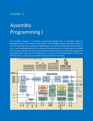
  • 1. Chapter 2 Assembly Programming I The assembly language is a low-level programming language that is particularly useful for Embedded Systems and Hardware Device Drivers. The Embedded Systems have fewer resources than PCs and mainframes. Assembly programming can be useful for optimizing code for speed or size in small embedded systems, the statements correspond directly to clock cycles and enables easier hardware-specific task. The control of Machine Code is better than a high level language, but the programmer must know the architecture for an exact microcontroller before he can write effective code. It’s necessary to consider that development time is longer.
  • 2. Assembly Programming………………….…………….…….………. 1 Memory Organization…..…………..………………….……………. 1 Data Memory (RAM).………………………….……………….……. 1 Program Memory (Flash/EE)……………….……………………...…. 3 Extended Data Memory (XRAM)………………………………………. 4 Data Memory (Flash/EE).……………..………………………..……. 4 Addressing Modes.……………..………………………..…………. 6 Interrupts.……………..……………...……………………..…… 6 Triggering an Interrupt by Software.……….……..…………….……. 8 Stack pointers and Interrupts.…………….……..…………….……. 8 Reset Interrupt.……….……..……………………………….…….9 Checklist for Interrupt Programs.……….……………………..………9 Example Program.………..…..……………………………….…….9
  • 3. Reset Value of Stack Pointer (07H) Memory Organization Data Memory (RAM) Memory Function 7FH 30H General Purpose (Direct or Indirect Addressing) 2FH . 20H 7FH Bit Addressable Area 00H 1FH . 18H Register Bank 3 PSW x x x 1 1 x x x 17H . 10H Register Bank 2 PSW x x x 1 0 x x x 0FH . 08H Register Bank 1 PSW x x x 0 1 x x x 07H . 00H Register Bank 0 PSW x x x 0 0 x x x Assembly Programming The MicroConverter® series of Analog Devices contains four different memory blocks: ✓ Data Memory (RAM): 256 x 8 ✓ Extended Data Memory (XRAM): 2K x 8 ✓ Program Memory (Flash/EE): 62K x 8 ✓ Data Memory (Flash/EE): 4K x 8 256 bytes 2k bytes 4k bytes 62k bytes RAM Flash/EE (Data) XRAM Flash/EE (Program) 1 The general-purpose RAM is divided into two separate memories, the upper and the lower 128 bytes of RAM. The lower 128 bytes of RAM can be accessed through direct or indirect addressing. The upper 128 bytes of RAM can only be accessed through indirect addressing because it shares the same address space as the SFR space, which can only be accessed through direct addressing. Lower 128 bytes: The lowest 32 bytes are grouped into four banks of eight registers addressed as R0 through R7. The next 16 bytes (128 bits), form a block of bit addressable memory space (00H – 7FH). The last block (30H-7FH) is for general purpose. After Reset, the SP register contains value 07H. As we push data onto the stack, the SP is incremented.
  • 4. It’s a good programming technic change the SP value to higher memory space (e.g. 70H), avoiding the lost of the Register Bank 1. The Register Bank is selected using PSW (Program Status Word) CY (PSW.7) Carry Flag. This flag is set whenever there is a carry out from the D7 bit. Affected after an 8-bit addition or subtraction. AC (PSW.6) Auxiliary Carry Flag. Set when there is a carry from D3 to D4 during an addition or subtraction operation. F0 (PSW.5) General Purpose Flag. RS1 (PSW.4) Register Bank Selector Bit 1. RS0 (PSW.3) Register Bank Selector Bit 0. OV (PSW.2) Overflow Flag. This flag is set whenever the result of a signed number operation is too large. F1 (PSW.1) General Purpose Flag. P (PSW.0) Parity Flag. If the A register contains an odd number of 1s, then P = 1. Therefore, P = 0 if A has an even number of 1s. CY AC F0 RS1 RS0 OV F1 P Assembly Programming Assembly Programming 2
  • 5. Program Memory (Flash/EE) Program Memory is used for permanent saving program (Machine Code). Flash/EE memory combines the flexible in-circuit reprogrammable features of EEPROM with the space efficient/ density features of EPROM which is based on a single transistor cell architecture. Depending on the settings made in compiler, program memory may also used to store a constant variables. After Reset, the Microconverter begins execution from address 0000H. The following program test PSW Register. The resulting Machine Code in program memory is shown below Assembly Programming Assembly Programming The above program tests the Data Memory (RAM), using indirect, direct and bit addressing , the value of the memory locations are shown below 3
  • 6. The internal XRAM (2K x 8) can be used as an extension of RAM (only 256 x 8). By default, this memory is not active. The XRAM can be enable using CFG832 register (MOV CFG832, #01H). The transfer with XRAM Memory is implemented using MOVX instructions. An example of use of this memory is shows below The 4 kBytes of Flash/EE data memory are configured as 1024 pages, each of 4 bytes. A group of four data registers (EDATA1–4) is used to hold the four bytes of data at each page. The page is addressed via the two registers, EADRH and EADRL as is shows in the table The ECON register is an 8-bit control register that may be written with one of nine Flash/EE memory access commands to trigger various read, write, erase, and verify functions. Extended Data Memory (XRAM) Data Memory (Flash/EE) Page Address (EADRH/L) EDATA 1 EDATA 2 EDATA 3 EDATA 4 3FFH Byte 1 ( 0FFCH) Byte 2 ( 0FFDH) Byte 3 ( 0FFEH) Byte 4 ( 0FFFH) .. .. .. .. .. 001H Byte 1 ( 0004H) Byte 2 ( 0005H) Byte 3 ( 0006H) Byte 4 ( 0007H) 000H Byte 1 ( 0000H) Byte 2 ( 0001H) Byte 3 ( 0002H) Byte 4 ( 0003H) Assembly Programming Assembly Programming 4
  • 7. The core cannot respond to interrupt requests until the Flash/EE operation is complete, some operations like ERASE command, can delay until 2 msec. Assembly Programming Assembly Programming 5
  • 8. The Vector Address represents the address of the interrupt service routine. The Interrupt Bit represents the bits that are “set” when the equivalent interrupt is requested. We can cause an interrupt with an instruction that “set” the interrupt flag. The Priority Level control the order in which multiple interrupts will be serviced. In case of multiple interrupts, the following rules apply: ✓ While a low priority interrupt handler is running, if a high priority interrupt arrives, the handler will be interrupted, and the high priority handler will run (interrupt inside interrupt). ✓ If a high priority interrupt is running, it cannot be interrupted by any other. ✓ A low-priority interrupt handler will be invoked only if no other interrupt is already executing. ✓ If two interrupts occur at the same time, the interrupt with higher priority will execute first. If both interrupts are of the same priority, the interrupt which is higher in polling sequence will be executed first. Addressing Modes Addressing Mode Assembler Instruction Example Description Immediate MOV A, #data MOV A, #30H Transfers an 8-bit data immediately Direct MOV A, direct MOV A, 30H 30H is the address where the operand is stored Register Direct MOV A, Rn MOV A, R5 Registers can take value from R0,R1…to R7 Register Indirect MOV A, @Ri MOV A, @R0 R0, R1 has the address where the operand is stored Indexed MOVC A, @A+DPTR MOVC A, @A+DPTR The source operand is @A+DPTR Interrupts Int. Number Interrupt Name Vector Address Interrupt Bit Priority Level 0 External Hardware (INT0) 03H IE0 3 1 Timer/Counter 0 overflow 0BH TF0 5 2 External Hardware (INT1) 13H IE1 6 3 Timer/Counter 1 overflow 1BH TF1 7 4 UART 23H RI/TI 9 5 Timer/Counter 2 overflow 2BH TF2/EXF2 10 6 End of ADC Conversion 33H ADCI 4 7 SPI/I2C 3BH ISPI/I2CI 8 8 Power Supply Monitor 43H PSMCON.5 1 9 Time Interval Counter 53H TIMECON.2 11 10 Watchdog timer 5BH WDS 2 Addressing mode is a way to address an operand. It can be a direct address of memory, register, numerical data etc. Assembly Programming Assembly Programming A single microcontroller can serve several devices. There are two ways to do that: Interrupt or Polling. In the Interrupt method, whenever any device needs its service, the device notifies the microcontroller by sending it an interrupt signal. Upon receiving an interrupt signal, the microcontroller interrupts whatever it is doing and serves the device. The program associated with the interrupt is called the Service Interrupt Routine (ISR). In Polling, the microcontroller continuously monitors the status of a given device; when the status condition is met, it performs the service. After that, it moves on to monitor the next device until each one is serviced. The advantage of interrupts is that the microcontroller can serve many devices (not all at the same time, of course); each device can get the attention of the microcontroller based on the priority assigned to it. The most important reason that the interrupt method is preferable is that the polling method wastes much of the microcontroller’s time by polling devices that do not need service. The following table shows the typical interrupts in Microconverters based on 8052 core 6
  • 9. The following program shows how an External Interrupt 0 is attended Assembly Programming Assembly Programming There are three interrupt-related Special Function Registers. IE (Interrupt Enable): EA (IE.7). Enable all interrupt sources (1 = enable; 0 = disable) EADC (IE.6). ADC Interrupt (1 = enable; 0 = disable) ET2 (IE.5). Timer 2 interrupt (1 = enable; 0 = disable) ES (IE.4). UART serial port interrupt (1 = enable; 0 = disable) ET1 (IE.3). Timer 1 interrupt (1 = enable; 0 = disable) EX1 (IE.2). External Interrupt 1 (1 = enable; 0 = disable) ET0 (IE.1). Timer 0 interrupt (1 = enable; 0 = disable) EX0 (IE.0). External Interrupt 0 (1 = enable; 0 = disable) IP (Interrupt Priority): RESERVED (IP.7). Reserved for future use PADC (IP.6). ADC interrupt priority (1 = high; 0 = low) PT2 (IP.5). Timer 2 interrupt priority (1 = high; 0 = low) PS (IP.4). UART serial port interrupt priority (1 = high; 0 = low) PT1 (IP.3). Timer 1 interrupt priority (1 = high; 0 = low) PX1 (IP.2). External Interrupt 1 priority (1 = high; 0 = low) PT0 (IP.1). Timer 0 interrupt priority (1 = high; 0 = low) PX0 (IP.0). External Interrupt 0 (1 = enable; 0 = disable) IEIP2 (SECONDARY INTERRUPT ENABLE REGISTER, No Bit Addressable) RESERVED. Reserved for future use PTI. Priority for time interval interrupt PPSM. Priority for power supply monitor interrupt PSI. Priority for SPI/I2C interrupt RESERVED. This bit must contain 0 ETI. Enable interval counter interrupt (1 = enable; 0 = disable) EPSMI. Enable power supply monitor interrupt (1 = enable; 0 = disable) ESI. Enable SPI or I2C serial port interrupt (1 = enable; 0 = disable) 7
  • 10. The program is stored in memory as shows bellow The interrupt program of the above section is executed by falling edge on P3.2. The same occur when you set IE0 (SETB IE0). Set the equivalent interrupt bit is equivalent to generate an interrupt by software. A stack operates in a last-in/first-out sense. When a new data item is entered onto the top of a stack (push), the stack pointer increments to the next physical memory address, and the new item is copied to that address. When a data item is pulled (pop) from the top of a stack, the item is copied from the address of the SP, and the SP decrements to the next available item at the top of the stack. The most general types of stack-specific instructions are: PUSH (put data onto the stack), POP (“remove” data from the stack), CALL (jump to a subroutine), RETURN (return from a subroutine) and INTERRUP. Triggering an Interrupt by Software Stack Pointer and Interrupts Assembly Programming Assembly Programming After RESET, the Program Counter (PC) has the value 0000H, where the Microconveter take the Operation Code (OC) of the first instruction to be executed (JMP). Address ROM Instruction Machine code PC 0000H JMP 000AH 02H (OC) 0000H 0001H 00H 0000H 0002H 0AH 000AH . . . . 000AH SETB IT0 D2H (OC) 000AH 000BH 88H 000CH 000CH SETB EX0 D2H (OC) 000CH 000DH A8H 000EH 000EH SETB EA D2H (OC) 000EH 000FH AFH 0010H 0010H SETB P2.5 D2H (OC) 0010H 0011H A5H 0012H 0012H MOV PCON,#22H 75H (OC) 0012H 0013H 87H 0015H 0014H 22H 0015H 0015H NOP 00H 0015H 0016H NOP 00H 0016H 1 1 The PC takes the value of the address where the OC of the next instruction is stored. 2 2 3 The program Stop the Execution, waiting for an External Interrupt 0. The PC has the value of the address where the OC of the next instruction is stored (0015H). 3 4 4 Address RAM Value 07H (SP) 08H (SP+1) 15 (PC, LS Byte) 09H (SP+2) 00 (PC, MS Byte) The external interrupt 0 is activated with the falling edge on P3.2. IE0 of TCON goes high. The Stack Pointer (SP) is increased, and the PC is stored on Stack (Least significant byte first). 5 5 Address ROM Instruction Machine code PC 0003H CLR P2.5 C2H (OC) 0003H 0004H A5H 0005H 0005H RETI 32 (OC) 0005H The PC is initialized with the 0003H address ( INT0 Interrupt address of the ISR from the interrupt vector table of). It starts to execute the interrupt service. subroutine 6 6 7 The interrupt routine is executed until RETI instruction, which clear IE0 of TCON, indicating that the servicing of the interrupt is over. Get pop PC (0015H) from Stack, decreasing SP 2 times and tacking its original value (07H) 7 8 8 The Microconverter continues the execution of the program that was interrupted 8
  • 11. ✓ Vector Address: Address of the Interrupt Service Routine (ISR). Place ISR, which is terminated by RETI instruction. ✓ Unconditional jump to anywhere in program memory: There are only 8 bytes between ISR Addresses. ✓ Redefine the value of the Stack: You must ensure that there is sufficient RAM capacity in the STACK to handle all interrupts, PUSH instructions to save registers and CALL to subroutines. Redefine the Stack avoid the loss of Register Bank 1. ✓ Protect your registers: An interrupt must leave the processor in the same state as it was in when the interrupt initiated. In general, your interrupt routine must protect the following registers: • PSW • DPTR (DPH/DPL) • PSW • ACC • B • Registers R0-R7 ✓ Pop the same number of values off the stack as you pushed onto it, take care of the order (last in/first out). ✓ Prioritize interrupts properly. ✓ Keep ISR short, use flags. ✓ The interrupts must be enable by software. Enable the global interrupt control bit. ✓ External interrupts: Level or Edge triggered. Reset Interrupt Checklist for Interrupt Programs Example program Assembly Programming Assembly ProgrammingRESET is the highest priority interrupt. A high level on RESET pin for 24 master clock cycles while the oscillator is running resets the device. As result PC = 0000H, where must be defined the OC of the first instruction to be executed. RESET can be executed by software, using following program 9 1 1 Vector Address (INT0) 2 2 Stack redefinition 3 3 Interrupt priority 4 4 New address for ISR 5 5External interrupt: Falling edge 66 Interrupt enable
  • 12. Assembly Programming Assembly Programming 10 4 7 Used registers are saved 7 8 8 Used registers are restored: Inverse order (last in/first out)