SlideShare ist ein Scribd-Unternehmen logo
1 von 71
Downloaden Sie, um offline zu lesen
Design and build a Raspberry
Pi robot
By
Stewart
Watkiss
(PenguinTutor)
About this guide
This is a guide to creating Ruby Robot. An inexpensive robot vehicle controlled by a Raspberry Pi
computer.
Copyright
This guide is provided through a creative commons license - Attribution-ShareAlike 3.0 Unported.
License details: http://creativecommons.org/licenses/by-sa/3.0/
About the author
Stewart Watkiss graduated from The University of Hull, UK, with a masters degree in electronic
engineering. Since then he has been working in the IT industry, including Linux and networking.
Linux has been his passion for many years and he has gained certification at LPIC-2. He runs the
website PenguinTutor.com providing information on learning Linux, electronics and the Raspberry
Pi. After working on several projects with the Raspberry Pi, both on his own or with his children, he
signed up as a STEM ambassador to pass some of his knowledge on to school children helping out
at local schools.
He has also been technical reviewer of the book “Learning Raspberry Pi with Linux”, published by
Apress, and a volunteer guest writer for The MagPi free magazine.
DRAFT Version
Contents
Table of Contents
Contents................................................................................................................................................1
Introduction..........................................................................................................................................3
How to use this guide...........................................................................................................................3
Knowledge required.............................................................................................................................4
Design decisions...................................................................................................................................4
Creating a design specification.............................................................................................................4
Design specification for robot vehicle.............................................................................................5
Deciding on main components.............................................................................................................5
Magician chassis kit.............................................................................................................................7
Raspberry Pi.........................................................................................................................................8
Raspbian Linux operating system....................................................................................................9
Initial configuration of the Raspberry Pi............................................................................................10
Download the NOOBS image........................................................................................................10
Connect the Raspberry Pi for first time install...............................................................................11
A basic introduction to the Linux command line...........................................................................13
Connect the robot to an existing Wi-Fi network............................................................................15
Installing additional software on Linux.........................................................................................16
Create a Wi-Fi hotspot for the Raspberry Pi..................................................................................17
Check the dongle supports Wireless Access Point mode..........................................................17
Configure the static IP address..................................................................................................18
Configure the DHCP server......................................................................................................18
Configure the Wireless Access Point software..........................................................................20
Logging on to the Raspberry Pi using SSH..............................................................................21
Adding the Raspberry Pi to the robot chassis.....................................................................................25
Power for the Raspberry Pi and motors.........................................................................................25
Shared or separate power supplies.................................................................................................26
Pre-supplied power supply.............................................................................................................27
Connecting the power...............................................................................................................27
Connecting the breadboard to the Raspberry Pi GPIO.............................................................27
Electronic circuit................................................................................................................................30
H-Bridge motor controller.............................................................................................................30
H-Bridge using relays / transistors / FETS / ICs...........................................................................32
SN754410 quad half-H driver IC..............................................................................................33
GPIO ports.....................................................................................................................................35
Circuit diagram...................................................................................................................................37
Breadboard design..............................................................................................................................38
Creating a more permanent circuit (stripboard vs PCB)...........................................................40
Printed Circuit Board - RyanTeck PCB kit RTK-000-001........................................................40
With diodes or without diodes..................................................................................................42
Heatsink....................................................................................................................................43
Controlling the speed of the motors with PWM............................................................................43
Writing the software to make it work.................................................................................................44
1
DRAFT Version
Basic software design points..........................................................................................................45
Using the design to provide implementation details......................................................................45
Choosing the programming language.......................................................................................46
Getting started with Python...........................................................................................................46
Learning to program in Python......................................................................................................49
Programming the GPIO with Python.............................................................................................50
Remote control Python program....................................................................................................51
Testing the robot.................................................................................................................................53
Adding a camera.................................................................................................................................53
Using the camera...........................................................................................................................55
Developing the robot vehicle further..................................................................................................56
Remote control vs. autonomous robots..........................................................................................56
Adding additional sensors..................................................................................................................57
What is I2C and SPI?.....................................................................................................................57
What's next?........................................................................................................................................58
Appendix A – Shopping list................................................................................................................59
Appendix B – Software requirements specification...........................................................................60
Software requirements specification for Ruby Robot v1...............................................................60
Appendix C – Program listing robotcontrol.py..................................................................................62
Appendix D – Key codes for remote control program.......................................................................65
Glossary..............................................................................................................................................66
2
DRAFT Version
Introduction
This project is designed as a way of learning physical computing (the combination of computer
programming with electronic circuits) in a fun way.
When first starting out with electronics then getting a LED to flash can be quite exciting, and
getting it to respond to programming done on a computer is another big leap, but once you have
mastered those skills then it can be easy to lose interest. What we need is something that is exciting,
fun to make, something you can show off to friends. The next challenge is that it needs to be
affordable. It needs to be within a reasonable price that children (or their parents) can pay for an
educational toy; unfortunately for most of us this rules out Lego Mindstorms and many commercial
robots.
I therefore started looking for an inexpensive robot vehicle kit that could be used for others learning
about robotics. The result was the Ruby Robot shown on the front cover. The reactions I have had
when taking the robot out in public has shown that children do indeed get excited when they see a
robot, especially when you let them have a go at controlling it using a mobile phone or tablet.
This guide is a detailed guide intended for young makers, teachers, computing or STEM club
leaders, or parents.
How to use this guide
The guide is designed to be worked through page by page following the instructions on your own
Raspberry Pi and robot chassis. The commands are shown with a grey background that should be
entered in to the Raspberry Pi, or that represent what the completed code should look like. You
should also consider the different options highlighted (see the chapter on Design decisions) for
opportunities to personalise your own robot vehicle.
If you are already familiar with a particular topic or are more interested in other parts then it is fine
to skip that section or to just focus on the actions in that section.
At the end you will have a robot vehicle which is similar to the one described, but with your own
personal characteristics. Hopefully you will also learn about the various aspects involved in the
design and build of the robot and most importantly have fun in doing it.
If you are going to create the robot then you are going to need some parts. I've created a parts list in
Appendix A which should be enough to get started. You may want to add other things later, but this
is enough to be starting with.
3
DRAFT Version
Knowledge required
This project is designed for secondary school children or those studying further education. Some
basic knowledge of the Raspberry Pi will be useful (http://www.penguintutor.com/raspberrypi/) or
some experience of running Linux and the command line interface on another computer. I have
included some more links to related websites within this guide, or you could learn from a Linux or
Raspberry Pi book such as Learn Linux with Raspberry Pi published by Apress or through the
MagPi magazine (http://www.themagpi.com/) . A very basic understanding of electronic circuit
theory would also be useful. More advanced topics are explained in detail in this guide.
An understanding of Python programming would also be an advantage. You don't need to know
Python programming to create the robot, although will help with understanding the code works. You
will need to know some programming if you want to make most of the suggested improvements so
it is worth taking the time to learn Python.
The robot can also be a used with younger children by skipping some of the theory and just
configuring as per the guide. For example it is possible to build the robot and then program it
without needing to understand any of the electronic circuitry.
Design decisions
Whilst it's possible to follow the exact same design as I put down here there are lots of opportunities
to do things differently. The design of the robot should become part of the learning experience. This
allows the designer, or engineer to use the correct term, to create a unique robot that is individual to
them and perhaps one that is more appropriate to specific tasks.
One of the reasons for using the magician robot chassis is that this is a versatile base that allows
components to be mounted in any number of different ways. This allows a unique robot to be
created. Some of the things to consider are direction of the robot, and the position of the Raspberry
Pi, the electronic circuit and the batteries. There are no right and wrong ways to locate these, but
there are often pros and cons depending upon the specific use. Some of these advantages and
disadvantages may not become apparent until later in the project, but this is all part of the learning
experience.
I will explain some of the pros and cons in the relevant sections. Look out for the light-
bulb sign as an opportunity to customise the design.
Creating a design specification
Before starting on any project then you need to know what you are going to make. This may seem
obvious, but turning this into a written specification can help with decisions that need to be made
4
DRAFT Version
later on. The design specification should describe the aims of the project rather than the actual parts
and devices to be used. You may already have an idea of how you will make the project, but as you
list the specification you may think of other ideas. There is no need to include the software design at
this stage, that will be covered later.
The amount of detail you include in the design specification will depend upon the complexity of the
project and who the intended audience is. If it's just for a simple project for a hobby then you can
keep it fairly brief, but if you are going to be asking for someone to fund your project or will be
providing a write-up as part of a school or college project then you may need to provide a more
detailed specification. I have created a simple design specification for this project as it's an informal
project that I created for myself. I have started with a brief summary and then provided a list of
requirements. In some cases I have given some flexibility within the requirements (such as referring
to a computing devices rather than a specific computer or model of phone that it should be
controlled by), whereas some are more specific (such as maximum budget). Each specification
should be something that can be tested to test that it is met. Most of the specification is mandatory,
but I have also included a “nice to have” feature.
Design specification for robot vehicle
This aim of the project is to create a robot vehicle that can be controlled from a computer or mobile
phone. This is being made as a fun project that can help demonstrate the principles involved in
designing and building a project. The vehicle should be relatively cheap and simple to build so that
it can be replicated by a school or college student.
• It should be simple to make using tools available in a standard workshop.
• Vehicle should be able to move around on an even floor (such as carpet or wooden floor).
• It should be possible to control the vehicle using a computer or other computing device.
• Maximum cost is £100 (excluding batteries and optional camera).
• It should be able to have a camera mounted to take photos of the environment.
◦ Live view or video recording would be an advantage (not required).
• It should provide some flexibility for adding additional features.
• It should be self powered.
• Communication should be wireless so that no cables are required connecting to the vehicle.
• The vehicle should be small enough so that it can be taken to events to give demonstrations.
Deciding on main components
The decision for the main components can now be made based upon whether they meet the
specification. Although all the factors were considered the two main requirements for determining
5
DRAFT Version
the main components were cost and that is should be simple to make with standard tools.
Whilst I haven't included a list of available tools within the specification I have referred to tools
used in a standard workshop, which means that standard screwdriver may be required, but it should
not require a laser cutter or 3D printer which whilst becoming more popular is not found in your
typical workshop. There is potentially a grey area in between, such as whether a solder iron is
available, which is an example of something you may need to clarify when working on a design.
You may need to go back to the project sponsor to ask them to confirm whether it is required (which
in the case of a hobby project may be yourself). As you will see later for this project a soldering iron
is not actually required although it can be useful, particularly when looking at expanding the project
in future.
Without a laser cutter then this is going to mean using a robot kit or creating one from hobby
components. Of course if you do have access to some more specialist tools then you have more
flexibility in your design which would allow you to make a truly custom robot.
The two main components that were decided upon were the Magician Robot Chassis for the body
and wheels, with a Raspberry Pi to control it.
Before finalising the design it is a good idea to consider alternatives. I was not able to find an
alternative robot chassis that would fit in with the specification (mainly because of the cost aspect),
although since starting there are some clones of the magician robot and at the time of writing there
is a simpler single layer design looking for funding through Indiegogo. I also considered an Arduino
compared with a Raspberry Pi for the processor. The decision to use the Raspberry Pi came down to
supporting wireless control (it is possible with Arduino, but adds significant additional cost) and
that programming a Raspberry Pi is generally considered easier than programming an Arduino.
Having decided on the Raspberry Pi another decision to be made was what wireless method to use.
The two most common ways of communicating using wireless are Wi-Fi (wireless networking) or
Bluetooth. Neither of these are included in the Raspberry Pi, but can be added easily with a low cost
USB adapter. Wi-Fi was chosen because of it's flexibility (it can also be used to configure the
Raspberry Pi) and flexibility for sending images from the camera.
In use I have found one disadvantage to using Wi-Fi, which is that it is prone to interference from
other Wi-Fi networks. The robot uses a small USB dongle which does not have the signal strength
to compete with strong wireless access points (WAP) if they are in the same room. I found that I had
to keep the tablet I was connecting with close to the robot if it was using the same channel as a
nearby WAP. The Wi-Fi configuration can be changed to use a different channel, which may need to
be changed when taking the robot to a different site.
More detailed decisions needed to be made later on in the design process, but having decided on
this main components made the remaining decisions easier later on.
6
DRAFT Version
Magician chassis kit
The magician chassis is a commercial robot vehicle kit available from several electronic and robot
suppliers. The chassis appears to have been created with the Arduino in mind as the power
connector from the battery pack matches with the Arduino power supply. This is something we will
address later when we look at connecting the power supply to the Raspberry Pi.
Instructions for assembling the kit are provided and are fairly easy to follow. When complete it
should look like the photo below.
If you follow the instructions provided with the magician robot chassis then the battery
holder will be installed on the lower platform. The advantage of this is that it leaves
plenty of space on the top to create the electronic circuits, but does mean having to
unscrew the top of the robot chassis to be able to change the battery. You may prefer to
have the battery on the top of the chassis so it is easier to swap batteries. An alternative is to swap
the batteries for a rechargeable unit that can be charged when installed on the robot; this will
however increase the cost so it has not been considered at this stage. For now I suggest you install
the batteries on the bottom so that it is easier to create / modify the electronic circuit on the top of
the chassis.
Looking at the underside we can see how the robot vehicle will move around. There are two main
drives wheels each of which is connected to it's own motor. There is then caster which is effectively
a large ball-bearing which can move in any direction.
Note that there are two discs on the motor shafts. These are not used at the moment, but are useful
for being able to determine how far the vehicle has travelled. We will look at this later in the guide,
for now take care not to lose these discs.
7
DRAFT Version
Now is a good idea to decide which direction is forward. The motors can be driven in
either direction controlled by the electronic circuit and whilst there are advantages to
having the driving wheels towards the front, particularly when travelling uphill, the
motors provided are not going to be able to climb more than a very gentle slope so this
is not much of an issue. In my initial version of the robot I have chosen the square end with the
caster as the front, as the Raspberry Pi camera mount fits well on the straight edge. If you are
looking to install sensors to determine if the robot reaches a wall you may instead prefer to use the
curved edge as the front as there are more holes and space for mounting other sensors. If you
change your mind then it's only a software change and it can drive in the opposite direction, but
moving the position of the camera and Raspberry Pi is a little harder later.
Raspberry Pi
The robot chassis appears to have been designed for use with the Arduino, which is an open source
programmable controller. Whilst the Arduino can control the motors and make simple decisions
based on input sensors it does not have the processing capability as the Raspberry Pi, which is what
we are using in this project. The Raspberry Pi is a small low cost computer designed specifically for
education. It is based around an ARM processor which can run the open source Linux operating
system and includes a GPIO (General Purpose Input Output) connector which can be used to
interface to electronic circuits that can control the robot. The Raspberry Pi can also be connected to
a camera which gives the robot the ability to see it's surroundings, or can be used to send images
back to the operator.
There are currently two different models of the Raspberry Pi. The model A is more basic with only
one USB port, no wired Ethernet port and only 256Mb of memory, the model B includes additional
features including an additional USB port, ethernet port and an increase to the amount of memory to
512MB. The model A is also less expensive.
8
DRAFT Version
The Raspberry Pi model A is recommended for this project as we won't be using a wired Ethernet
port and the model A uses less power than the model B. The fact that the model A uses less power is
useful when running on batteries. It can still run on a Raspberry Pi model B if you have one already,
but you may need to consider a different power supply (see later).
It's not possible for the Raspberry Pi to control the motors directly, so we are also going to need an
electronic circuit. When designing a circuit it's a good idea to start by using a prototyping
breadboard so we'll be adding a breadboard onto the robot chassis.
The Raspberry Pi and breadboard can be installed in various different positions on the
robot chassis. These can be installed on either the top or bottom plates of the chassis.
For now I recommend using the top layer for the breadboard as it will make it easier to
make any changes to the electronic circuit.
You will need to consider the length of the cables required as well as any connectors on the
Raspberry Pi that you would like to connect to. For example the camera comes with only a short
ribbon cable to connect it to the Raspberry Pi, which is the reason I placed the Raspberry Pi close to
the camera. I also put the Raspberry Pi with the GPIO connector closest to the breadboard so that
only a short lead is required to connect to the breadboard. If you are going to be using a Wi-Fi
dongle you need to ensure there is space near the USB ports for the dongle (such as by having the
USB port point towards the side or the chassis) and if you want to add a speaker (so the robot can
speak) then you should ensure that there is space by the 3.5mm audio socket to plug in a speaker
cable. Finally whilst you won't be connecting the robot directly to a TV or monitor when it's in use
it may be a good idea to leave space near the HDMI connector to be able to connect a screen when
doing the initial set-up. Access to the HDMI port is not actually required as the set-up can be done
on a different Raspberry Pi / computer or the Raspberry Pi could be temporarily disconnected when
a new image is created.
Raspbian Linux operating system
The recommended operating system to run on the Raspberry Pi is Raspbian Linux. This is a
distribution specifically created for the Raspberry Pi based upon Debian Linux. It can be purchased
pre-installed on a SD card from the main suppliers (look for recent version of NOOBs SD cards), or
can be downloaded from the Raspberry Pi website for install onto an SD card
http://www.raspberrypi.org/downloads .
Linux is a free open source operating system. It is free for anyone to use and its source code is
available. Much of the software within the distribution is provided under the GPL (GNU General
Public License) which means that if you modify and share the code then you need to make your
modifications available under the same conditions.
If you are familiar with other operating systems such as Windows, then you will find the Linux
graphical desktop (sometimes referred to as a GUI – Graphical User Interface) familiar. It has a
9
DRAFT Version
look and feel more reminiscent of older versions, which is due to the low specification processor
needing a leaner operating system. Modern Linux distributions running on a powerful computer
provide a more feature rich experience.
One thing that is different to some other operating systems is that you can run the full operating
system without needing to have a graphical environment loaded and you can run commands on the
computer remotely using the command line. This may be a little strange for those used to clicking
on icons, but provides a lot of control and is very powerful. It is particularly useful in projects such
as this robot where we can control and program the robot without needing to connect it to a monitor
or TV.
It may be useful to spend some time getting familiar with Linux before embarking on the rest of this
project. To find out more about the Linux operating system see
http://www.penguintutor.com/linux/about-linux or one of the many guides on Linux or the
Raspberry Pi.
Initial configuration of the Raspberry Pi
We will need to make some configuration changes to the Raspberry Pi configuration to allow us to
use certain features.
Download the NOOBS image
In this section we will set-up the Raspberry Pi with the Raspbian operating system. If you are
already familiar with the Raspberry Pi and have set-up the operating system then you can skip this
section, but ensure you read the section on creating a Wi-Fi hotspot if you would like to be able to
control the robot outside of the range of your home wireless network.
For this project we will be using the Raspbian operating system. This is easiest to install using the
NOOBS software image. You can purchase an SD card with the operating system pre-loaded or you
can download the software for free and install it onto a standard SD card. I assume you have an
existing SD card and will be downloading the image from the Internet.
You will need a 4GB SD card (or micro-SD card in an SD adapter). If it is a new pre-formatted card
then you should be able to use it as it is, but otherwise you should format the card using the SD card
association's formatting tool: https://www.sdcard.org/downloads/formatter_4/
Formatting the card and running the NOOBs initial configuration will delete all
the data on the SD card. Make sure you have made a copy of any data you want to
keep before formatting the card.
10
DRAFT Version
Download the NOOBS image from the Raspberry Pi website:
http://www.raspberrypi.org/downloads
You need to select the standard NOOBS image rather than the Lite version (especially if you are
using a model A which has no ethernet port). The image is over 1GB in size and is usually quicker
to download using a torrent client, although there is a standard web link on the website as well.
This guide is based on NOOBs version 1.3.2, although it should work for future versions as well.
Once you have downloaded the file (it should have a file ending with .zip) you should extract the
files and copy all the files from the zip to the SD card.
Note: Ensure you copy the contents from inside the zip file – not the zip file itself.
Connect the Raspberry Pi for first time install
The easiest way to perform the initial configuration of the Raspberry Pi is to connect it temporarily
to a TV or screen and keyboard. The Raspberry Pi can be connected to a TV using a standard HDMI
cable, or if you have a monitor that has a DVI connector then you can connect it to that using a
HDMI to DVI connector. Alternatively you can use the RCA composite connector to connect to an
analogue TV; if using an analogue TV you will need to press a button during start-up so that it
knows to use the RCA connector (press 3 for PAL as used in most of Europe or 4 for NTSC used in
the USA).
Your SD card should be inserted in the slot on the Raspberry Pi and a keyboard in the USB port.
The initial configuration can be performed with just a keyboard which is good as we don't have
enough USB ports on the Model A to connect a mouse as well. If you do want to use a mouse then
you may need to use a USB hub.
Finally insert a micro-USB power supply (used for most mobile phones) into the power socket and
the NOOBS first start screen will appear on the screen. Choose to install the Raspbian operating
system which is the recommended choice (press space) and then press i to start the install. It will
take a while to repartition the SD card and install the operating system, after which it will restart
with the Linux operating system.
11
DRAFT Version
There is some useful information displayed on the screen during the install, but don't worry if you
miss any of the messages as this guide provides all the instructions for this particular set-up.
Installing an operating system is often a good time to put the kettle on and get yourself a hot drink
ready for when we get to the fun stuff.
After the operating system boots for the first time the Raspberry Pi Software Configuration Tool
will run (raspi-config). This tool gives a menu which makes it easier to configure some features of
the operating system. I have listed some of the useful options below:
Change User Password – Recommended to keep your system secure. The default username is pi
and the password is raspberry.
Enable Boot to Desktop – This is not required for a robot. It provides a graphical interface similar
to that used by Windows
Internationalisation Options – If you are in the UK then you don't normally need to change this. If
you are in a different country or use a non-UK keyboard then you may want to change this to your
local country.
Enable Camera – This is required if you want to use the Raspberry Pi camera module
Advanced Options – You can reduce the memory allocation to 16MB and provide a unique
hostname for your Raspberry Pi. It is normally a good idea to check for an updated version as well,
but that is only possible when connected to the Internet.
Once you have made the changes choose finish and then reboot the Raspberry Pi.
12
DRAFT Version
If you need to make any changes to these in future you can launch the configuration tool by running
sudo raspi-config
A basic introduction to the Linux command line
Once the operating system has been installed you should see a lot of text scroll across the screen.
Do not be alarmed this is the normal behaviour. Most computers will also generate similar
messages, but it is often hidden from the user to make a computer appear to be more user friendly.
In fact this is often hidden when using Linux on a regular PC, but for the Raspberry Pi it is useful
for those learning computing to see what is happening behind the scenes as well as being a useful
tool when things go wrong.
You may expect to see a graphical screen with icons that you can click, but we won't here. The
Raspberry Pi does have a graphical user interface (similar to windows), but we won't be using it in
this as we will be disconnecting the screen shortly. This is why I said not to enable the “Boot to
Desktop” option during the raspi-config. Instead we will be telling the computer what to do by
issuing instructions through a text based interface called the shell. This is often referred to as using
the command line. It may not feel as friendly as a graphical screen but it's not quite as scary as it
first seems and is in fact a very powerful way to communicate with a computer.
For now you can ignore the text from the computer starting up and wait until you get the login
prompt. Enter the username pi next to login: and press enter and then enter the password which will
be raspberry unless you changed it earlier. Note that you won't see any characters when you enter
the password, which is a security feature to prevent others from seeing your password. When
logged in you will see a line of text ending with a dollar symbol ($) at the bottom of the screen.
This line will be prefixed with some more information about the computer you are on.
On my robot it looks like:
pi@ruby-robot:~$
The $ symbol is call the command prompt and indicates that the shell (the interface to the
computer) is ready for input. The text at the left shows the username you are logged in as, the
hostname of the computer and the current directory that you are in. Another prompt you may see
ends with the hash symbol (#) instead of the $. The # denotes that you are running with super-user
privileges and you need to take additional care when running commands.
If you have used the Windows command mode (cmd.exe) then you will notice some similarities,
although there are some differences.
13
DRAFT Version
To see what directory (sometimes these are referred to as folders on Windows) you are currently in
use the pwd (print working directory) command. Just type pwd and hit enter:
pi@ruby-robot:~$ pwd
/home/pi
pi@ruby-robot:~$
The directory is shown on the next line - /home/pi and then it returns a prompt waiting for the next
command. You may notice that the directory separators '/' go the opposite way to what you see on
Windows; Unix (on which Linux is based) was around long before DOS (on which Windows
directory seperator is based). The /home/pi directory is the home directory for the user pi. The home
directory also has a special character '~' which is what we saw in the command prompt. Just note
that when you use ~ in a directory name then you can replace it with /home/username .
You can list the files in the current directory with the ls command, and you can move around into
different directories using the cd (change directory command).
To run a program you just enter it's name on the command line followed by enter. You can often
enter instructions (command options) to the command after the command name.
nano test.txt
This will run the nano text editor. It will edit the file test.txt and if the file doesn't already exist it
will create it. The nano editor is one of the easiest editors to use on the command line and so we
will use it later. To save the contents of the editor to the current file use <Ctrl> O (hold down the
Ctrl key whilst pressing the O key). Then use <Ctrl> X to exit. You can see the available
instructions at the bottom of the editor page.
GNU nano 2.2.6 File: test.txt
[ Read 0 lines ]
^G Get Help ^O WriteOut ^R Read File ^Y Prev Page ^K Cut Text ^C Cur Pos
^X Exit ^J Justify ^W Where Is ^V Next Page ^U UnCut Text^T To Spell
To learn more about the Linux command line see:
14
DRAFT Version
http://www.penguintutor.com/linux/
Connect the robot to an existing Wi-Fi network
Whilst we could configure the Raspberry Pi to an existing home wireless network this will mean
that if you take the robot away from home then it will not be possible to communicate with the
robot. We will therefore set-up the Raspberry Pi as a Wi-Fi hotspot.
To do this we need to install some additional software and for that we need a working network
connection. If you have a model B with an Ethernet port and have a wired network router handy
then you can connect the network direct to a router and install the packages that way (in which case
jump to the next section on installing additional software), but if you are using a model A then we
need to connect to a wireless network to download the software.
First we need to edit the /etc/interfaces file which tells the operating system how to configure the
network interfaces. The example I have used is based upon the nano editor. Run the command:
sudo nano /etc/network/interfaces
Note that I have prefixed this with sudo, which allows us to edit the file as a system administrator
(root user). If you don't add sudo then you will get a warning “No write permission” in nano and
you will not be able to save the file.
Look for the entry iface wlan0 inet dhcp and add the following entries below it:
wireless-mode managed
wireless-essid <SSID>
wireless-key <Passphrase>
Replace <SSID> with the name of your wireless network and <Security key> with your network
security passphrase. If you have not changed these and have a wireless router supplied by your
broadband provider then they are most likely shown on the rear of your wireless router.
The following shows an example of what to look for (these are made up based on an example
Virgin Media router):
Wireless SSID: virginmedia0123456
Wireless Key (Passphrase): dh3892jhndkl
You can restart the networking, but I recommend rebooting at this stage to make sure it comes up
15
DRAFT Version
from a reboot.
sudo reboot
Installing additional software on Linux
Assuming you now have a working Internet connection (see previous section on configuring
wireless networking first) we can now update the software on the Raspberry Pi and add the
packages we will need later.
This needs to be done prior to configuring the Raspberry Pi as a wireless hotspot as we will be
creating an independent network and so will lose our connection to the Internet.
There is a Raspberry Pi App store which is based on a similar concept to mobile phone App stores,
but there is also a software installer for Linux that uses a similar way of installing software over the
Internet which was in use long before the App Stores.
We will be using the apt-get tool to install software, which installs software that is supplied in the
Debian package format. This is used for the main operating system (and we will use this to upgrade
any updated files) as well as numerous software packages ranging from simple tools (mostly what
we are installing here) to a fully fledged software package such as an office suite or photo editor.
The software installed through apt-get is free and does not install adware on your computer.
First we will update the list of software to find any changes and then install any changes to the
operating system. This is done with the following two commands:
sudo apt-get update
sudo apt-get dist-upgrade
This may take a while to run as it downloads any updates to the Raspbian operating system since
the NOOBS image was created.
Now that the system is up to date we can install the additional software. These can be installed in a
single command, but I have put these down separately with a short explanation. We will be
configuring these later, for now just install them whilst you still have network connection.
The iw command will be used to query the wireless network interface. It's not actually required, but
can help to spot potential problems with the dongle.
sudo apt-get install iw
16
DRAFT Version
The hostapd is the software used to configure the computer as a wireless access point. It is a
daemon which runs in the background to handle the wireless networking.
sudo apt-get install hostapd
To provide an IP address to the clients that connect we use DHCP. This can be run on the Raspberry
Pi through the ISC DHCP server.
sudo apt-get install isc-dhcp-server
Note that whilst installing the dhcp server you may get an error saying that it has not been possible
to start the dhcp server. You can ignore the warning for now, once we have configured the server it
should start correctly.
If there is any more software that you know you will need later then you can add it now as it will be
harder to install later when we have reconfigured the networking.
Create a Wi-Fi hotspot for the Raspberry Pi
We can now reconfigure the Raspberry Pi as a Wireless hotspot so that we can connect to the robot
from anywhere even if there is no other wireless network signal.
This needs a number of different networking services to work. I will briefly explain each one as I
add it, but it would be too much to explain each in detail in this guide. More information about
Networking on Linux is available from: http://www.penguintutor.com/linux/#Networking
Check the dongle supports Wireless Access Point mode
First we can check if the wireless dongle supports Access Point mode (WAP). The majority of
dongles do, but it saves spending time trying to configure this on the robot if the dongle doesn't
support it.
Run:
iw list
Within the Supported interface modes look for an entry for AP
eg.
Supported interface modes:
* IBSS
* managed
* AP
* AP/VLAN
* WDS
17
DRAFT Version
* monitor
* mesh point
As long as that is included then the dongle can act as an access point.
If there is too much information to see you can view the output through the less command.
iw list | less
Use the cursor keys to move around and q to quit when you have finished.
Configure the static IP address
We now need to reconfigure the network with a static IP address. Whilst it is possible to use the
same IP address range as you have on your existing Wi-Fi network we can avoid some potential
problems by using a different network range. This will help if you try and connect from a computer
that is connected to your local network (using wired ethernet) and you are connecting to the robot
using wireless.
There are a number of network ranges that are reserved for local use (chances are that your
normally wireless network uses one of these ranges). I have chosen the network 10.5.5.0 / 24 as this
is less commonly used. We will set the robot to 10.5.5.1 which is the first usable IP address in that
range.
sudo nano /etc/network/interfaces
Find the entry for the wireless LAN which we changed previously (wlan0).
Remove the iface wlan0 entry and the wireless network information and replace with:
iface wlan0 inet static
address 10.5.5.1
netmask 255.255.255.0
Configure the DHCP server
IP addresses can be statically configured so that they don't change (as we need to configure on the
robot), but most end users connect with a dynamic IP address which is allocated to the computer
when it connects to the network. This is done using a protocol called DHCP (dynamic host
configuration protocol). We can configure the Raspberry Pi as a DHCP server so that it can provide
the IP address for the clients to use.
18
DRAFT Version
This is configured in the /etc/dhcp/dhcpd.conf file
sudo nano /etc/dhcp/dhcpd.conf
We will be using the IP address of the robot to connect to it so we don't need the domain name
entries in the dhcpd.conf file. Comment out the domain-name entries by prefixing each line with a
'#' as below.
#option domain-name "example.org";
#option domain-name-servers ns1.example.org, ns2.example.org;
Make this the authoritative DHCP server by removing the # character in front of the authoritative
keyword as below:
# If this DHCP server is the official DHCP server for the local
# network, the authoritative directive should be uncommented.
authoritative;
Edit the section titled “#A slightly different configuration for an internal subnet” so that it looks like
this:
# A slightly different configuration for an internal subnet.
subnet 10.5.5.0 netmask 255.255.255.0 {
range 10.5.5.100 10.5.5.150;
option routers 10.5.5.1;
option broadcast-address 10.5.5.255;
default-lease-time 600;
max-lease-time 7200;
}
This will allocate addresses between 10.5.5.100 and 10.5.5.150.
Save and exit from the file.
Now edit the default start script to set the interface.
sudo nano /etc/default/isc_dhcp_server
change the interfaces to:
INTERFACES=”wlan0”
The dhcp server is now configured. We could start it manually now, but instead we will reboot the
Raspberry Pi when we have completed the rest of the steps.
19
DRAFT Version
Configure the Wireless Access Point software
The configuration for the wireless access point should go into a new file /etc/hostapd/hostapd.conf
This file doesn't currently exist, but if we try to edit a file that doesn't exist then nano is smart
enough to realise it needs to create a new file.
sudo nano /etc/hostapd/hostapd.conf
Add the following – inserting your own wireless SSID and passphrase as appropriate.
# Host access point config file
# device name
interface=wlan0
# Driver interface
driver=hostap
# SSID for the network
ssid=<SSID>
# set appropriate country parameters (maybe required for regulatory reasons)
country_code=GB
# Operation mode - for 802.11n still use g to indicate using same band as g
devices
hw_mode=g
# set channel - channel=0 for Automatic Channel Select
channel=0
# mac address access list - 0 = accept unless in deny
macaddr_acl=0
# Use shared key authentication
auth_algs=1
# Enable WPA2
wpa=2
# set passphrase
wpa_passphrase=<passphrase>
# Use WPA PSK
wpa_key_mgmt=WPA-PSK
# Pairwise cipher for WPA (v1)
wpa_pairwise=TKIP
# Pairwise cipher for RSN/WPA2
20
DRAFT Version
rsn_pairwise=CCMP
Now add the configuration file to the hostapd startup file.
sudo nano /etc/default/hostapd
Add entry:
DAEMON_CONF=”/etc/hostapd/hostapd.conf”
Now reboot the Raspberry Pi. You should now be able to see your new wireless network with a
computer or mobile phone and connect to it using the appropriate passphrase. Remember you will
not have any Internet access. The only computer you will be able to connect to is the robot
Raspberry Pi at address 10.5.5.1
Logging on to the Raspberry Pi using SSH
Now that the Raspberry Pi has a working network connection it should be possible to remove the
connections to the screen and keyboard and continue the rest of the configuration over the network.
The usual way of connecting to a Linux computer is using SSH. This uses a text based client that
will run a shell on the “server” (see What is a server? below). It allows you to run commands in the
same way as we did for the configuration above, but across the network instead of needing to be on
the Raspberry Pi. SSH is an encrypted protocol so that it is not possible for others on the network to
see what commands are being issued and more importantly the username and password used to
login.
You can get an ssh client for most computers, including tablets and smart phones.
What is a server?
You may think of a server as being a computer sat in a dedicated data centre hosting a
website. Whilst that can be the case, any computer can actually act as a server for
certain functions, even a desktop computer or a mobile phone. When we talk about a server it is
whichever computer is running the code that allows a client (the opposite of a server) to connect to
it. The Raspbian operating system includes the OpenSSH server which is enabled by default to
allow a client to connect to the Raspberry Pi.
SSH has a lot more functionality than we are using here. SSH can be configured to use key based
authentication providing a secure way of connecting from one computer to another without needing
to login manually (which is useful for automation). SSH can also be used to create tunnels to direct
network traffic over an encrypted session over an insecure network. For more details see:
http://www.openssh.com/
21
DRAFT Version
Using SSH from a linux or MAC OS X computer
On Linux (including the Raspberry Pi), and Mac OS X you can run ssh from a terminal shell. The
terminal shell may have a different name depending upon the Linux distribution, the most common
names are: Terminal; LXTerminal or Konsole. The client is normally OpenSSH which is run from
the shell. There are alternative ssh clients including PuTTY which is a GUI based application, but
still uses the same text based shell for running commands on the remote computer. See the next
section on SSH in Windows if you'd like instructions for PuTTY.
Once in the terminal shell you can issue the ssh command, which should be followed by the
username you want to connect as, an @ sign and the IP address of the computer to connect to.
You can see this in action below.
stewart@linux-pc:~$ ssh pi@10.5.5.1
The authenticity of host '10.5.5.1 (10.5.5.1)' can't be established.
RSA key fingerprint is 09:b4:41:4c:b5:c1:4a:94:62:54:e3:b0:5f:78:71:d2.
Are you sure you want to continue connecting (yes/no)? yes
Warning: Permanently added '10.5.5.1' (RSA) to the list of known hosts.
pi@192.168.0.11's password:
The programs included with the Debian GNU/Linux system are free software;
the exact distribution terms for each program are described in the
individual files in /usr/share/doc/*/copyright.
Debian GNU/Linux comes with ABSOLUTELY NO WARRANTY, to the extent
permitted by applicable law.
pi@ruby-robot:~$
I started out logged in as username stewart on my Linux computer linux-pc. You can tell the
computer I am logged in as in the prompt (before the $ sign).
From this computer I entered the command “ssh pi@10.5.5.1” which connected to the robot
Raspberry Pi. This is the first time it has connected to this computer and so it provides some details
about the computer so you can decide if that is the correct computer.
If you want to check you are connecting to the correct computer then you can run the “ssh-keygen
-l” command when physically connected to the computer. You will need to provide the appropriate
file where SSH has stored the key. In reality if this is your local network and you know this is a
computer you have not connected to before then you can just accept the connection using 'yes'. If in
future you get a warning that the key has changed then you should take extra care in case someone
is masquerading as your computer, although if you have re-installed the operating system that will
also generate the same warning.
It then asks for the password of the computer I was connecting to. Once entered correctly it shows
the standard login banner for that computer.
22
DRAFT Version
You can now see from the prompt that I am now logged in to a different computer – username pi on
computer ruby-robot. From now on any commands entered will be run on the remote computer
“ruby-robot” and not the computer that I am typing on. When using ssh get used to looking at the
computer name on the command prompt before issuing a command to make sure you are on the
correct computer.
Using SSH from a Windows computer
Unlike other operating systems Microsoft Windows does not normally include an ssh client. There
are a number of free ssh clients for Windows. PuTTY is one of the most popular clients. It is a
graphical application, but still provides the same text based interface that is used by the standard
OpenSSH client used in Linux.
You can download it from: http://www.chiark.greenend.org.uk/~sgtatham/putty/
You can either download the executable file putty.exe, which can be saved onto your local
computer, or as an installer which includes a file transfer client and other tools.
When you run PuTTY you will be presented with the following startup screen. You can enter the IP
address of the Raspberry Pi 10.5.5.1 in “Host Name (or IP address)”. The port can be left at the
default of 22 and then click open.
23
DRAFT Version
This is the first time PuTTY has connected to this computer and so it provides a security alert with
some details about the computer so you can decide if that is the correct computer.
If you want to check you are connecting to the correct computer then you can run the “ssh-keygen
-l” command when physically connected to the Raspberry Pi. You will need to provide the
appropriate file where SSH has stored the key. In reality if this is your local network and you know
this is a computer you have not connected to before then you can just accept the connection using
'Yes'. If in future you get a warning that the key has changed then you should take extra care in case
someone is masquerading as your computer, although if you have re-installed the computer that will
also generate the same warning.
24
DRAFT Version
You will now be presented with a login prompt where you can login with the username and
password for the Raspberry Pi. After logging on any commands entered will be run on the remote
computer “ruby-robot” and not the computer that I am typing on. When using ssh get used to
looking at the computer name on the command prompt before issuing a command to make sure you
are on the right computer first.
Adding the Raspberry Pi to the robot chassis
We now have the robot chassis built and Raspberry Pi configured so that we can connect to it over
the network; it's now time to put the two together. The Raspberry Pi can be installed anywhere on
the chassis. The key things to consider are the length of the camera cable (if using a Raspberry Pi
camera) and the cable from the GPIO to the breadboard. In the robot vehicle shown the Raspberry
Pi is at the front (or at least what I designated as the front) so that it could use the standard cables. If
you would rather install it elsewhere then you may need to get longer cables.
There are two holes on the Raspberry Pi board that be used to secure it using the PCB stands
provided with the robot chassis.
Power for the Raspberry Pi and motors
The Raspberry Pi needs a power supply of 5V. This is the standard supply from a USB socket and
for the power used for most modern mobile phones. The tolerance of the supply is ± 0.25V which
means that the power supply should be between 4.75V and 5.25V. If the supply falls below 4.75V
then it is likely to have problems, typically the USB devices stop working first, but other problems
may occur (such as unexpected reboots). More than 5.25V and there is a risk of damage to the
Raspberry Pi.
The power supply needs to be able to supply a running current of around 300mA for the model A or
25
DRAFT Version
700mA if using a model B. This is the main reason that the model A is better suited for this project,
to reduce the load on the power supply.
The motors supplied with the magician chassis are designed for a maximum of 6V. If you factor in
the voltage drop within the electronic circuit then ideally it should have a higher power supply.
Whilst we haven't decided on how to switch the motors yet you could consider about 1 volt voltage
drop in the circuitry. So we should therefore be looking for a power supply of about 7V, which is
required to run the motors at full power. Through testing I have found that the particular motors I
have will run on a 5V supply even with our control circuitry. If using 5V the motors will be running
with less power than if the supply to the motors is 6V, but in tests it was shown to be sufficient for
moving the robot around on a relatively flat surface.
Shared or separate power supplies
As the power requirements for the motors and the Raspberry Pi differ then ideally they should either
have separate power supplies, or a single power supply that is regulated down to the supply voltage
of the Raspberry Pi. Doing so would also with preventing noise on the power supply which will be
generated when the motor is turned on and off. To add a second supply (or to upgrade the power
supply with an additional regulator circuit) could add significant additional cost.
If this was a commercial project, and in particular if this had a mission critical application then it
would be important to work within the specification of all the components. In fact for mission
critical equipment then it is common to over-engineer a solution to make sure it will continue to
perform beyond it's designed capability. This could be achieved using two separate power supplies:
a dedicated USB supply for the Raspberry Pi and a higher voltage power supply capable of
providing the full voltage for the motors.
One of the main criteria was for the cost to be kept low and as an educational and demonstration
vehicle there is no risk if it doesn't perform correctly. Obviously we would still like this to be as
reliable as possible as it can be embarrassing when trying to demonstrate something that doesn't
work. Testing was performed to to ensure that the motors did work at a reduced voltage and this was
considered adequate for this project.
If you come across any power related issues when building your own (or unexplained problems
with the Raspberry Pi) then you may need to to add a separate power supply for the Raspberry Pi. It
is possible to test whether power is the cause of problems by using a temporary power supply for
the Raspberry Pi to see if it eliminates the problem.
26
DRAFT Version
Pre-supplied power supply
The chassis kit comes with a battery holder designed for 4 x AA batteries. The nominal voltage for a
standard AA battery is 1.5V which gives 6V for the 4 batteries in series, but rechargeable batteries
(NiCd / NiMH) have a lower nominal voltage of 1.2V which gives 4.8V.
The actual voltage of the batteries will depend upon charge and how much current is being drawn
from them. In my experience rechargeable NiMH batteries work well with the robot. I expect
standard Alkaline batteries will work as well, but that would be at your own risk as you will be
applying more than the recommended voltage to the Raspberry Pi and any connected USB devices.
I recommend using high-capacity NiMH batteries in the supplied battery holder.
You may wish to consider other battery types, such as high capacity batteries designed
for remote control cars (which could be used with a regulator to power the Raspberry Pi
and motors) or mobile phone top-up batteries (to provide a second power supply
dedicated to the Raspberry Pi). The maximum supply voltage for the Raspberry Pi
should not be exceeded if using a non USB based power source.
Connecting the power
Power is normally provided to the Raspberry Pi using a micro-USB connector, however the power
connector on the battery holder is provided as 2.5mm DC plug. An alternative way to connect the
power supply to the Raspberry Pi is through the GPIO connector.
I have used a 2.5mm DC socket to terminal connector which is then wired to the breadboard used
for the electronic circuit. The power is then connected to the Raspberry Pi through the GPIO port.
Care must be taken when connecting power through the GPIO port as it bypasses the
poly-fuse included used to protect the power coming from the micro-USB port. Using 4
x AA batteries should work fine with this set-up, but additional protection should be
considered if using different batteries.
Connecting the breadboard to the Raspberry Pi GPIO
The GPIO port on the Raspberry Pi is a 26-way male header connector on the edge of the board.
27
DRAFT Version
The individual pins can be connected direct to the breadboard using male-to-female jumper leads,
which is the cheapest way, but I chose to use a Raspberry Pi breakout cobbler board. The cobbler
board is a small PCB with a 26-way connector that matches the one on the Raspberry Pi GPIO. A
ribbon cable is used to connect between the GPIO on the Raspberry Pi and the cobbler. It is
important to connect the ribbon cable the correct way around, on the cobbler there is normally a gap
in the connector housing to ensure the cable can only be inserted one way around, but the Raspberry
Pi GPIO does not have that luxury. Pin 1 is marked on both the Raspberry Pi and the cobbler and
the ribbon cable should be positioned so that wire number 1 (normally coloured red) aligns with pin
1 at both ends.
The cobbler is normally provided as a kit that you need to solder yourself. Soldering is a useful skill
for creating electronic projects, but you could ask someone solder these for you if you don't want to
learn soldering just yet.
Soldering is not difficult, but it does have an element of risk due to the hot element
which will be at several hundred degrees Celsius. It is important to ensure that the
soldering iron is stored on a proper stand and always treated with appropriate care.
Children should only use a soldering iron when under appropriate supervision from a
competent adult.
One of the advantages of the cobbler is that it makes it easier to remove the Raspberry Pi (which I
found useful when sharing a Raspberry Pi between the robot and a Code Club I was running), but
also that it makes it easier to see the pin designation on the breadboard.
Since creating my robot RasPi.TV has released some new expansion boards for the Raspberry Pi,
which includes a Breakout board that is an alternative to using the cobbler. It works almost in
reverse to the cobbler in that it puts the breakout pins on an expansion board on the Raspberry Pi
GPIO rather than on the breadboard. An advantage of this is that it still makes it easy to see the port
labelling and disconnect from the Raspberry Pi, but doesn't use up space on the breadboard.
28
DRAFT Version
Below is a diagram of the GPIO connector showing its different pin references.
The numbers in the corner are the port numbers. These are numbered 1 to 26, numbered vertically
from the top right. Where there are two GPIO numbers this refers to a change between revision one
and two of the Raspberry Pi, where a second reference is shown it refers to an alternate usage of the
pin (such as I2
C, SPI or serial communication).
To provide the power supply through the GPIO then any of the Gnd and 5V0 pins can be used. In
this case I have used pin 2 for the 5V supply and pin 24 for the ground connection. I first connected
the power supply to the power rails on the breadboard and then connected from those to the
appropriate pins on the GPIO port.
There is no input protection for any power supply connected directly through the GPIO
port. Please read the warnings regarding the choice of power supply, or consider adding
your own fuse protection prior to the power supply connecting to the Raspberry Pi. A
safer alternative to connecting through the GPIO is to cut up an existing micro-usb cable
and connect the red wire to the 5V supply and the black wire to Gnd. The white and green wires are
for data and are not connected on the Raspberry Pi so can be cut off. If using the micro-usb
connector the Gnd connection should still be connected on the GPIO connector, but the 5V one
should not.
Note that the power supply ports are labelled as 5V0, which really means 5.0V (or five
volts). This is how electronic circuits are usually labelled to avoid ambiguity, especially
when using small writing. For example we also have some ports labelled as 3V3 which
provide a 3.3V feed from the Raspberry Pi. Written in small writing the decimal point is
barely visible and would be easy to miss (is it 33V or 3.3V? - quite a difference!). A similar
convention is used for resistors where a 100Ω (one hundred ohm) resistor would be labelled as
100R and a 2.2KΩ resistor would be labelled as 2K2.
Once the battery is connected it should be possible to connect the batteries and power up the
Raspberry Pi. Do not be tempted to connect the motors directly to the GPIO as it can damage the
29
GPIO connector
1
3V3
GPIO0/2
SDA
GPIO1/3
SCL
GPIO4
CPCLK0
Gnd
GPIO17
GPIO21/27
GPIO22
3V3
GPIO10
MOSI
GPIO9
MISO
GPIO11
SCLK
Gnd
5V0
5V0
Gnd
GPIO14
TXD
GPIO15
RXD
GPIO18
PCM_CLK
Gnd
GPIO23
GPIO24
Gnd
GPIO25
GPIO8
CE0
GPIO7
CE1
2
25
26
DRAFT Version
Raspberry Pi.
Electronic circuit
Now that we are able to power the Raspberry Pi from the batteries we can look at the electronics
required to drive the motors. As I have already stated it is not possible to power the motors directly
from the GPIO ports. Firstly the GPIO can only supply 3.3V output whereas the motor is designed
for 6V, but also the amount of current that can be supplied through the GPIO would be only a
fraction of what we actually need to run the motor.
The GPIO ports from the Raspberry Pi connect direct to pins on the processor. There is
no protection to protect the processor against faulty wiring or too high a voltage on the
pins. The GPIO ports are designed for 3.3V operation and connecting these directly to a
5V power source could permanently damage the Raspberry Pi.
H-Bridge motor controller
Before I get to the actual circuit (which is pretty simple) here is some of the theory of how a H-
bridge motor controller works.
The motors supplied are basic DC motors with built in gears. These kind of motors have only two
wires which are for the power. The direction of the motor is determined by the direction of the
current through the motor, so by reversing the positive and negative supply we can make the motors
change direction.
The H-bridge configuration is a common way to change the direction of the power supply. The h-
bridge is named as it is shaped a little like a letter H and uses two pairs of switches that need to be
switched together. It is easiest explained using diagrams.
The switch pairs are diagonally opposite to each other. Each pair of switches need to be closed at
the same time. So on the diagrams below S1 and S4 form one pair and S2 and S3 the other pair.
This is the H-bridge in it's off position. All four switches are turned off and no power is provided to
the motor.
30
DRAFT Version
When S1 and S4 are closed the positive supply goes to the left of the motor and the negative to the
right. The motor will then work in one direction.
To change the direction switches S1 and S4 need to be opened and then S2 and S3 closed. The
positive supply is now provided to the right of the motor and the negative to the left, so the motor
31
M
+V
Gnd
S1 S2
S3 S4
M
+V
Gnd
S1 S2
S3 S4
+ -
DRAFT Version
will now turn in the opposite direction.
It is important that S1 and S3 are never closed at the same time and the same with S2
and S4. Switching these on together would create a short circuit across the power
supply.
H-Bridge using relays / transistors / FETS / ICs
The H-bridge circuit can be created using a variety of different components.
A relay is perhaps the easiest to understand as the relay is a physical switch which replaces each of
the switches shown. It also has the advantage that very large loads can be switched if appropriately
sized relays are used, or if the load is smaller a compact reed relay can be used.
The two disadvantages are that some kind of buffer is required and the lack of speed control.
Buffers are required as relays can need a significant amount of current to activate and even a small
reed relay will need more than the GPIO can provide. In the case of a small relay a simple transistor
switch could be used to activate the relay, or this can be done using a PiFace digital (see
http://www.piface.org.uk/ for more details about PiFace).
The other disadvantage, which is a bigger problem, is the lack of speed control. The speed of a DC
motor depends upon the strength of the magnetic field which is created by the current flowing
32
M
+V
Gnd
S1 S2
S3 S4
- +
DRAFT Version
through the motor coils. The strength of the magnetic field can be controlled by changing the
voltage at the motor. Using an on/off switch will mean that the voltage and current to the motor is
fixed (although it could be altered using additional circuitry to change the voltage that is provided
as the Vcc of the H-bridge). The technique we will be using to change the speed of the motor is
based upon rapidly turning the switches on and off which is not possible with relays that have a
slow switching speed.
The next suggestion is using either transistors or FETs (Field Effect Transistors). These are discrete
components that act as amplifiers by switching a current through a pair of terminals based upon a
small current on a third terminal (or voltage input in the case of an FET). These can be used as
electronic switches by providing them with an apprporiate input. Using transistors then S1 and S2
would be PNP transistor and S3 and S4 would be NPN transistors. A similar configuration is
required for FETs where S1 and S2 would be P-channel FETs and S3 and S4 would be N-channel
FETs.
It can be a useful exercise to build a H-bridge using discrete transistors, but for the
purposes of controlling the robot vehicle then I recommend using an existing integrated
circuit or a Raspberry Pi expansion board. If creating a transistor / FET circuit then you
need to ensure that the transistors are not switched in such a way as to cause a short
circuit.
The recommended way of creating the H-bridge is to use an existing integrated circuit (IC). These
have the advantages of fast switching capability that is provided by an active transistor circuit, but
with the convenience of this being in a single package. Another advantage is that the IC will
normally be configured so as to not allow the switches to be turned on in a way that would cause a
short circuit. The ICs normally do this by having a single in-signal for each half of the H-bridge to
determine direction, with an enable signal to determine whether the motor should be on or not.
One disadvantage of using an IC is that it cannot be used to control large motors. That is not an
issue for this design.
SN754410 quad half-H driver IC
The use of an integrated circuit has clear advantages and makes the circuit for controlling the robot
vehicle motors simple. The SN754410 IC has been chosen as it is inexpensive, widely available and
is TTL compatible so it can be used directly with the 3.3V signals from the Raspberry Pi.
data sheets are a useful source of information when designing electronic circuits. For an
integrated circuit they will normally provide: an explanation about what the integrated
circuit can be used for; the recommended voltages and operating conditions and often
include example circuit diagrams of how they can be used. data sheets are normally
created by the manufacturers and are often available through electronic component retailers or can
be found through an Internet search.
33
DRAFT Version
This integrated circuit is a quad half-H driver which provides four modules. Combining two of
these modules provides a single H-bridge circuit. We can therefore use one IC to control two
motors.
The PIN layout is shown below:
The logical diagram shows how the four half-bridge modules can be configured as a pair of H-
bridge controllers.
To check that the IC is suitable we should refer to the data sheet available from the manufacturer (in
this case Texas Instruments). According to the data sheet the IC can be used to switch up to 1A for
supplies of 4.5V to 36V, and includes a separate power supply for the input to output. All inputs are
compatible with TTL and CMOS logic with the 3.3V from the GPIO fitting within the input high
range of between 2 and 5.5V. This shows it as being suitable for this install.
34
DRAFT Version
There are two different ways of using the input signals for the H-bridge controller.
One way is to have a single output for the motor direction which is inverted between the two inputs,
and then use the enable pin to turn the motor on and off. So for example if you had a high direction
input that would go to input 1A and inverted low at input 2A and the opposite to change direction.
This will just require two outputs from the Raspberry Pi, but would need an inverter to be added to
the circuit. Or this could be implemented by having three outputs from the GPIO with one being
inverted.
The other option, which is the one we will use here, is to permanently enable the EN pin by
connecting it to high and then using the two inputs to turn the motor on and off as well as to
determine the direction. This is achieved by setting both 1A and 2A to low, which is the off state
and then turning one of these high to turn the motor on and set the direction.
GPIO ports
There are 26 pins on the Raspberry Pi GPIO connector; of these pins 17 can be used as inputs or
outputs for the Raspberry Pi. To control the motors we need four of these to be used as output pins.
35
DRAFT Version
Pin No. Designation Pin No. Designation
1 3V3 2 5V0
3 4 5V0
5 6 Gnd
7 8
9 Gnd 10
11 GPIO 17 12
13 GPIO 21/27 14 Gnd
15 GPIO 22 16 GPIO 23
17 3V3 18 GPIO 24
19 20 Gnd
21 22 GPIO 25
23 24 GPIO 8
25 Gnd 26
GPIO 0/2
SDA
GPIO 1/3
SCL
GPIO 4
CPCLK0
GPIO 14
TXD
GPIO 15
RXD
GPIO 18
PCM_CLK
GPIO 10
MOSI
GPIO 9
MSO
GPIO 11
SCLK
GPIO 7
CE1
Whilst any of the pins labelled as GPIO can be used there are some that reduce compatibility
between different versions of the Raspberry Pi. This is due to an updated version of the Raspberry
Pi Model B (known as revision 2) released around September 2012. Whilst it is possible to detect
this in software and address the pins appropriately it is easier to avoid the pins that have changed
GPIO port reference (as shown with a / in the GPIO references).
If you would like to know what kind of Raspberry Pi you have then you can look at the
physical board for the screw mounting holes (which were not included on revision 1.0
boards), or from Linux run 'cat /proc/cpuinfo'. The hardware revision number will be 2
or 3 for a revision 1 board (the latter without the troublesome USB fuses), revision 2
boards have a higher number.
In the pin assignment list above there are also some ports that are used for specific purposes. For
example pins 8 and 10 are used for serial communications (by default are used as debugging
console) and there are several of the pins that are used for SPI or I2
C connections. The ports used
for SPI or I2
C can still function as standard GPIO ports, but they are useful for adding additional
sensors and outputs.
36
DRAFT Version
I originally chose ports that avoided the wires crossing on the breadboard, but since then the
RyanTeck RTK-000-001 motor controller was released. The RTK-000-001 is almost identical to my
design, but provides a PCB for mounting directly on the Raspberry Pi and due to the orientation of
the IC in relation to the GPIO connector it used different GPIO pins. I therefore changed my GPIO
port allocation so that the RTK-000-001 can be used as a direct replacement (more details later).
The GPIO ports used are as follows:
1A – GPIO 17 (pin 11)
2A – GPIO 18 (pin 12)
3A – GPIO 23 (pin 16)
4A – GPIO 22 (pin 15)
Circuit diagram
The circuit diagram below shows how the various components connect together.
In this diagram I have shown Vcc1 and Vcc2 as two different power supplies. In my case I
connected these together as I used the same supply for the Raspberry Pi and the motors.
37
DRAFT Version
Breadboard design
The breadboard is connected onto a breadboard (solder-less prototyping board). I have shown two
different breadboard layouts below.
This first layout is where the is a separate power supply connected to the Raspberry Pi to the one
used for the motors. The power to Vcc1 on the H-bridge IC is taken from the 5v pin on the GPIO
connector and so is powered from the Raspberry Pi.
38
IC1a
IC1b
IC1c
IC1d
M1
M2
1Y
2Y
3Y
4Y
RaspberryPi
GPIO
1,2 en
3,4 en
1A
2A
3A
4A
GPIO17
GPIO18
GPIO23
GPIO22
Vcc1
Vcc2
+5v
Gnd
Gnd
Gnd
+5v
DRAFT Version
Template from www.penguintutor.com
a
b
c
d
e
f
g
h
I
j
k
l
1 2 3 4 5 6 7 8 9 101112 13 141516 1718 19 20 21222324252627282930
1 2 3 4 5 6 7 8 9 101112 13 141516 1718 19 20 21222324252627282930
a
b
c
d
e
f
g
h
I
j
k
l
SN754410
+v
Gnd
Motor 1
Motor 2
Vcc1
4A
4Y
Gnd
Gnd
3Y
3A
3,4en
1,2en
1A
1Y
Gnd
Gnd
2Y
2A
Vcc2
GPIO connector
1
3V3
GPIO0/2
SDA
GPIO1/3
SCL
GPIO4
CPCLK0
Gnd
GPIO17
GPIO21/27
GPIO22
3V3
GPIO10
MOSI
GPIO9
MISO
GPIO11
SCLK
Gnd
5V0
5V0
Gnd
GPIO14
TXD
GPIO15
RXD
GPIO18
PCM_CLK
Gnd
GPIO23
GPIO24
Gnd
GPIO25
GPIO8
CE0
GPIO7
CE1
Motor power supply
The second shows how I connected the breadboard using a single power supply to provide the
power to the motors and the Raspberry Pi. Note that the power supply is connected through the
GPIO connector directly to the Raspberry Pi, bypassing the internal fuse. It is important that the
Raspberry Pi is not connected to another power supply when wired in this configuration.
Note that whilst the breadboard is solderless the GPIO breakout does need to be soldered.
Alternatively it can be replaced with male-female jumper wires from the breadboard onto the GPIO
connector on the Raspberry Pi.
39
Template from www.penguintutor.com
a
b
c
d
e
f
g
h
I
j
k
l
1 2 3 4 5 6 7 8 9 10111213141516 171819 20 21222324252627282930
1 2 3 4 5 6 7 8 9 10111213141516 171819 20 21222324252627282930
a
b
c
d
e
f
g
h
I
j
k
l
SN754410
+5v
Gnd
Motor 1
J2
Motor 2
Vcc1
4A
4Y
Gnd
Gnd
3Y
3A
3,4en
1,2en
1A
1Y
Gnd
Gnd
2Y
2A
Vcc2
GPIO connector
1
3V3
GPIO0/2
SDA
GPIO1/3
SCL
GPIO4
CPCLK0
Gnd
GPIO17
GPIO21/27
GPIO22
3V3
GPIO10
MOSI
GPIO9
MISO
GPIO11
SCLK
Gnd
5V0
5V0
Gnd
GPIO14
TXD
GPIO15
RXD
GPIO18
PCM_CLK
Gnd
GPIO23
GPIO24
Gnd
GPIO25
GPIO8
CE0
GPIO7
CE1
DRAFT Version
Creating a more permanent circuit (stripboard vs PCB)
The breadboard circuit is sufficient for a working robot vehicle, but it does not have the same
durability as a permanent circuit soldered together. Another reason for wanting to move the motor
control from the breadboard is to free up the space on the breadboard for connecting sensors
(although this could also be achieved by having a second breadboard with one mounted on the
lower level).
One way of creating a more permanent circuit is to solder the components onto stripboard.
Stripboard is a board with strips of copper on the underside which allow components to be soldered
to them. They are available either as generic stripboards with rows of copper strips, or with a layout
similar to the breadboard layout, which makes transferring the circuit easier. Whilst using stripboard
would create a more permanent circuit it wouldn't help with creating more space for future circuits
as the stripboard would be difficult to mount over the Raspberry Pi and if positioned where the
breadboard is would take about the same amount of space as the breadboard.
A better choice would be to use a printed circuit board (PCB). There are some existing printed
circuit boards that can be used with the Raspberry Pi or it is possible to create your own. When I
first designed the Robot Vehicle there were no motor circuit controllers that were commercially
available. I did look at the PiFace digital, but that only provided a pair of single-pole relays which
would only drive a pair of motors in one direction or a single motor in forward and reverse. I
therefore starting work on creating my own printed circuit board, but whilst I was doing that the
RyanTech motor controller board was made available which saved me the task of creating my own.
If you are interested in electronic circuit design then it is a useful exercise to create your
own printed circuit board. These can be designed manually or by using specialist PCB
software such as KiCAD or Fritzing (there are also commercial software which can be
very expensive). Creating your own PCB is fiddly and involves the use of some
dangerous chemicals, but it is very rewarding to have your own completed circuit board. If creating
your first PCB I recommend starting with a simple single sided PCB rather than trying to create the
motor controller.
Printed Circuit Board - RyanTeck PCB kit RTK-000-001
The add-on board for the Raspberry Pi that I moved my circuit to is the RTK-000-001 designed by
Ryan Walmsley. It is based on the same circuit as the breadboard design (I actually made a couple
of port changes from an earlier breadboard design to make it compatible).
I have referred to this as an add-on board, but another term you may hear used is shield.
The term shield if often used with add-on boards for the Arduino micro-controller board
where there are a variety of different boards that can be stacked on top of each other.
The motor controller board is provided in a kit form. It contains a PCB and the various components
40
DRAFT Version
which need to be soldered together. The connections from the board are made using terminal blocks
so once soldered together it can easily be used for other projects
The completed board is shown below. Note that the GPIO connector is mounted on the underside of
the PCB so that it fits onto the GPIO connector on the Raspberry Pi. The IC is mounted in a IC
socket which makes it easier to solder (there is no risk of damage the IC during soldering) and
means that the chip can be removed if required.
The photo below shows the controller board mounted on the Raspberry Pi.
41
DRAFT Version
External connections are required to connect the power supply to VCC2 and the motor connections
to the terminals M1 and M2. Also note that there is no connection for VCC1 on the controller board.
The IC on the motor board is powered from the GPIO, but a power supply needs to be provided to
the Raspberry Pi through the normal micro-USB connector. I cut off the large USB connector from
a USB to micro-USB lead and connected that to the power supply from the battery. There are four
wires used in a USB connector, but only the red (5v) and black (gnd) need to be connected to the
power supply.
With diodes or without diodes
Motors are electromagnetic devices. This means that they use the electronic current to create a
magnetic field which causes an action, in this case turn the motor around. When the power is
removed the magnetic field will collapse, or if the motor continues to turn then it can act as a
generator. When this happens there can be voltage spike caused by the back EMF (electromotive
force) which could damage sensitive electronic components. Normally a diode is connected in the
reverse direction across a magnetic load to prevent the back EMF from damaging the electronic
circuitry. These have various different names including flyback diodes, freewheeling diodes,
suppressor diodes or clamp diodes.
The data sheet for the SN754410 IC shows the internal circuitry based on the diagram below.
Through this you can see two diodes connected in reverse across the transistor output which will
help to dissipate the voltage spike. However the same data sheet also shows an example circuit
diagram where external diodes are connected.
42
DRAFT Version
Unfortunately the data sheet does not provide any guidance as to whether the internal diodes are
suitable for handing the back EMF from a diode. I have tested with the motors of the magician
robot chassis and have not experienced any problems.
Adding external diodes would only cost a small amount (typically a few pence per diode), however
adding them to the breadboard made the circuit more complex and harder to follow and they are not
included in the motor controller board.
If you are using the SN754410 for larger motors then I would suggest adding external diodes to
provide additional protection, but it does not appear to be necessary for this robot vehicle. There is
also an alternative IC the L293D which includes clamp diodes, although that IC is less readily
available.
Heatsink
I have not used an external heat sink on the motor controller IC for the robot vehicle. In normal use
I have not suffered any heat related problems. If using a motor powerful motor then it may be worth
adding an IC heatsink to the chip which may be useful if the motor stalls.
Controlling the speed of the motors with PWM
We have now built a circuit that will allow us to move the motors forwards and backwards, but we
also need to be able to control the speed. A common way to change the speed of a DC motor is to
change the DC voltage. As the voltage increases the magnetic field is more powerful and as it
decreases it produces a less powerful magnetic field. The circuit we have made is based on
switching the supply on and off rather than been able to provide a variable voltage, so what we need
is a way to make this digital on-off signal appear as though it's an analogue DC voltage.
There is a technique that can be used that can change the speed of the motor by switching the
supply on and off quickly. In fact this is a technique that can be used in other circumstances to
create an analogue output from a single digital signal.
The technique is called Pulse-width modulation (PWM). It works by switching the voltage on and
off very quickly. The ratio of time that the voltage is switched on compared to it being switched off
provides an equivalent voltage.
This is easier to understand by looking at a waveform diagram. The diagram below is simplified
from what the waveform actually does which is done to make the explanation clearer. The
waveform shows the voltage on the y-axis over time in the x-axis. The time is in milliseconds as
this all happens very quickly.
43
DRAFT Version
The blue waveform shows the output voltage used to drive the motor. It changes from 0V to 5V as
the controller is switched on (this shows only one direction – the other direction would be reversed).
The red waveform shows the equivalent voltage based on the percentage of time that the actual
voltage (blue) is turned on.
We start with the actual voltage completely off. The blue line (actual voltage) is at 0v as is the red
line (equivalent voltage). Then the power is applied for three tenths of a cycle and then turned off
for seven tenths of a cycle. This means that the equivalent voltage is three tenths of the voltage
which is 1.5V. Then the width of the PWM pulses increases so that it is on for six tenths and off for
four tenths which gives an equivalent of six tenths of the supply which is 3V. Finally the supply is
fully on giving an equivalent voltage of 5V. This is greatly simplified but shows how increasing the
width of the PWM pulses increases the voltage applied to the motor. The waveform above shows
how a motor could be accelerated, although in reality this would be over a much longer time period.
The waveform shows the voltage applied to the motor but it does not necessarily reflect
what actually happens with the motor. In reality the motor will not turn at all until the
supply is sufficient to get over the physical resistance posed by the motor and the
wheels connected to it. This is very different to how a stepper motor (different type of
DC motor) is controlled which allows the motor to be moved in individual steps corresponding to
different coils being powered on in the correct sequence.
It is possible to provide PWM using hardware or software. Hardware based PWM uses circuitry
within the processor to turn the pins on and off as appropriate, whereas software based PWM does it
using software running on the processor. Hardware driven PWM is usually preferred as it uses
minimal CPU load to implement, however the library chosen for this does not currently support
hardware based PWM. At the moment we will be using software based PWM, but in future versions
of the RPi.GPIO library that may change to hardware based. Also note that even with hardware
based PWM depending upon what else is running there is no guarantee that the code controlling the
PWM will be running when required. An alternative would be to use the Arduino (with or without a
Raspberry Pi) which can be much better at responding to events in real time.
Writing the software to make it work
We have now build the hardware including the electronic circuit to control the motors. What we
now need is the software to make it work. Before we start writing the software then we need to
determine what we expect it to do and how it should do it. If you are creating a formal project then
this is normally done through a formal software requirements specification (SRS). The software
44
DRAFT Version
requirements specification doesn't explain how the software is to be written, but should provide a
list of things that we need the software needs to perform to be successful. The detail of the
specification depends upon the size of the software project, but it's always a good idea to think
through the aims of the software before you start programming. I have included an example of a
software requirements specification in the Appendix, but I've created a more basic software design
guide below.
Basic software design points
This is a brief description of the software that we will need to design and some of the criteria of the
software.
The software created is to provide the control of a robot vehicle based around the Raspberry Pi
Ruby Robot. This software is intended as a demonstration of how the vehicle can be controlled, it
can then be used as a basis for future development of a program with improved functionality. The
software will allow a user to control the robot vehicle using key-presses and will control the motors
appropriately. It should allow change in speed and direction.
Will need to run on the Raspbian operating system
It should be easy to understand the software so that it can be developed further
It must be able to control the motor controller through the GPIO ports
Although it does not need to be network based it should be possible to control this by running over
a network based protocol (eg. ssh).
Using the design to provide implementation details
The software design is only a very brief example of what may be used. If you are at college then
you will need to follow their guidelines for any projects. Note that the specification doesn't provide
any details on what programming language to use or the specific details about how this should be
implemented. Instead it provides a high level overview of the important features which are used to
guide the decisions and then as a basis for checking if the objectives have been met when the
software is being developed and when it is complete. As with the design specification for the overall
project some aspects of the software design are a little vague: How do you measure how easy a
program is to understand?, but we can still use this as a guiding principle in the design of the
software.
Some things that may be appropriate to add are page layouts of the application pages or more
details of the way that the user interacts with the application. In this example we are just creating an
interactive command line application so it wasn't relevant.
45
DRAFT Version
Choosing the programming language
Whilst the choice of programming language often comes down to personal preference there are a
number of factors that should be considered when choosing a programming language especially if
the software may need to be maintained by others.
The main two factors that I used when deciding upon the programming language were the intended
audience and existing libraries that could be used. This is intended for teaching others that are new
to programming and Python is one of the most popular languages for learning programming,
especially on the Raspberry Pi. There are also some libraries written for Python to interact with the
GPIO ports including software based PWM. In particular the RPi.GPIO library is easy to use.
Getting started with Python
Unfortunately I don't have the space or the time to provide a comprehensive guide to learning
Python. There are however many books and guides dedicated to learning Python. What we will do
though is to consider how we can write the python code on the Raspberry Pi and an explanation on
how it works.
The first thing with Python is to decide what version to run. “Oh no not more choices!” I hear you
cry, but this is due to a transition that Python is going through. It's kind of the next step in becoming
an even better programming language. The older version of Python is version 2.7 which has been
around a long time and has lots of libraries written for it. The newer version is version 3 which has
many improvements, but is not backwards compatible and there are not so many libraries written
that work with version 3.
I tend to use version 2.7, partly because that's what I've been used to but also because it's currently
the default on the Raspberry Pi. Although both are installed, it is version 2.7 that will run if you just
type python on the command line:
$ python -V
Python 2.7.3
(note that the V should be a capital letter, lower case means something completely different).
There is a version of the RPi.GPIO module for both 2.7 and 3 and so this should run on either
version of Python.
The next thing is how to get the code onto the Raspberry Pi mounted in the robot vehicle. We can
either do this by plugging a screen, keyboard and mouse onto the Raspberry Pi (which is mounted
on the vehicle) or we can use our network connection to program or transfer the program to the
Raspberry Pi remotely. I will use the first example here as it's easier to understand, but
46
DRAFT Version
programming remotely can make it easier to make quick changes to your program when testing. For
now I'm going to assume you have a monitor (or TV) connected to the Raspberry Pi HDMI port and
a keyboard and mouse (perhaps through a USB hub). Alternatively you could edit the file directly
on the Raspberry Pi using ssh and the nano editor, or another alternative is to edit the file on your
desktop / laptop computer using your favourite text editor (such as IDLE or my personal favourite is
JEdit) and then save it as a text file and copy the file onto the Raspberry Pi using scp (part of the ssh
suite of tools).
When first setting up the Raspberry Pi we decided against booting to desktop (as when we don't
have a screen attached it's just a waste of resources), but using the GUI desktop will make it easier
for programming. So after logging in on the command line run startx to get to the desktop.
We will use the IDLE programming environment which provides a graphical editor as well as a
Python shell that can be used for testing the code. It also provides syntax highlighting, which means
that certain words will be displayed in different colours to make programming easier. Depending
upon your preference start either IDLE or IDLE3 for Python 2.7 or Python 3 respectively.
IDLE starts with a python shell. You can enter python commands straight into the shell and see how
the command works, but to add this program choose File→New to create a new file.
47
DRAFT Version
The code can then be entered into the program editor.
48
DRAFT Version
You can see one of the advantages of using the IDLE editor in that the code is colour coded to make
it easier to follow. If this is your first python program just enter:
print("Hello world!")
and then choose Run from the menu and you should see Hello world! 'printed' on the screen in the
python shell.
Learning to program in Python
If this is the first time you've programmed in python then I suggest you take a look at some other
resources to get you up to speed before continuing to the more complicated bits. Or if you can't wait
that long to get your robot working copy the code to get your robot up and running and then come
back to here so that you can understand how it works and how to make it work even better.
A good starting point for learning programming is the Raspberry Pi Education Manual. This is good
because it's FREE, but also it's been put together by some great teachers who volunteered their own
time to help teach programming:
http://pi.cs.man.ac.uk/download/Raspberry_Pi_Education_Manual.pdf
49
DRAFT Version
Some other books are listed on the web page below
http://www.penguintutor.com/programming/books#python
Programming the GPIO with Python
One of the reasons for choosing the Python programming language one the existing modules which
make accessing the GPIO port easy to code. The RPi.GPIO module is included in the Raspbian
image provided with NOOBs.
This will explain how the GPIO code is going to work, but there is no need to enter this at the
moment.
To use the RPi.GPIO module it first needs to be imported using the line:
import RPi.GPIO as GPIO
Access to the GPIO port requires root access, so it is recommended that the import statement is
wrapped in a try clause to provide a more user friendly error.
try:
import RPi.GPIO as GPIO
except RuntimeError:
print("Error importing RPi.GPIO! This must be run as root using sudo")
After loading the module we can select the appropriate numbering scheme for the GPIO ports.
There are two numbering schemes, one which refers to the pin numbers of the GPIO port (1 to 26)
and the other that uses the port numbering on the BCM2835 processor. I have used the processor
number scheme using the following instruction.
GPIO.setmode(GPIO.BCM)
We then need to set the mode for any GPIO ports that we use. The following sets the pin defined by
pin_number as an output pin.
GPIO.setup(pin_number, GPIO.OUT)
If we just wanted to turn the pin on and off then we could use
GPIO.output(pin_number, True)
50
Rubyrobot detailedguide

Weitere ähnliche Inhalte

Ähnlich wie Rubyrobot detailedguide

Advanced View of Projects Raspberry Pi List - Raspberry PI Projects.pdf
Advanced View of Projects Raspberry Pi List - Raspberry PI Projects.pdfAdvanced View of Projects Raspberry Pi List - Raspberry PI Projects.pdf
Advanced View of Projects Raspberry Pi List - Raspberry PI Projects.pdfWiseNaeem
 
Advanced View of Projects Raspberry Pi List - Raspberry PI Projects.pdf
Advanced View of Projects Raspberry Pi List - Raspberry PI Projects.pdfAdvanced View of Projects Raspberry Pi List - Raspberry PI Projects.pdf
Advanced View of Projects Raspberry Pi List - Raspberry PI Projects.pdfWiseNaeem
 
Advanced View of Projects Raspberry Pi List - Raspberry PI Projects.pdf
Advanced View of Projects Raspberry Pi List - Raspberry PI Projects.pdfAdvanced View of Projects Raspberry Pi List - Raspberry PI Projects.pdf
Advanced View of Projects Raspberry Pi List - Raspberry PI Projects.pdfWiseNaeem
 
Advanced View of Projects Raspberry Pi List - Raspberry PI Projects.pdf
Advanced View of Projects Raspberry Pi List - Raspberry PI Projects.pdfAdvanced View of Projects Raspberry Pi List - Raspberry PI Projects.pdf
Advanced View of Projects Raspberry Pi List - Raspberry PI Projects.pdfWiseNaeem
 
Visual Studio 2008 Beginning Asp Net 3 5 In C# 2008 From Novice To Professi...
Visual Studio 2008   Beginning Asp Net 3 5 In C# 2008 From Novice To Professi...Visual Studio 2008   Beginning Asp Net 3 5 In C# 2008 From Novice To Professi...
Visual Studio 2008 Beginning Asp Net 3 5 In C# 2008 From Novice To Professi...guest4c5b8c4
 
AIOT Server manual.pdf
AIOT Server manual.pdfAIOT Server manual.pdf
AIOT Server manual.pdfAyaGamal610138
 
Advanced View of Projects Raspberry Pi List - Raspberry PI Projects.pdf
Advanced View of Projects Raspberry Pi List - Raspberry PI Projects.pdfAdvanced View of Projects Raspberry Pi List - Raspberry PI Projects.pdf
Advanced View of Projects Raspberry Pi List - Raspberry PI Projects.pdfWiseNaeem
 
Raspberry pi: Conceptos básicos de robótica raspberry pi por richard grimmett
 Raspberry pi: Conceptos básicos de robótica raspberry pi por richard grimmett Raspberry pi: Conceptos básicos de robótica raspberry pi por richard grimmett
Raspberry pi: Conceptos básicos de robótica raspberry pi por richard grimmettSANTIAGO PABLO ALBERTO
 
Advanced View of Projects Raspberry Pi List - Raspberry PI Projects.pdf
Advanced View of Projects Raspberry Pi List - Raspberry PI Projects.pdfAdvanced View of Projects Raspberry Pi List - Raspberry PI Projects.pdf
Advanced View of Projects Raspberry Pi List - Raspberry PI Projects.pdfWiseNaeem
 
How To Do Everything With JavaScript
How To Do Everything With JavaScriptHow To Do Everything With JavaScript
How To Do Everything With JavaScriptAzharul Haque Shohan
 
Advanced View of Projects Raspberry Pi List - Raspberry PI Projects.pdf
Advanced View of Projects Raspberry Pi List - Raspberry PI Projects.pdfAdvanced View of Projects Raspberry Pi List - Raspberry PI Projects.pdf
Advanced View of Projects Raspberry Pi List - Raspberry PI Projects.pdfWiseNaeem
 
B1XdMQl1frS.pdf
B1XdMQl1frS.pdfB1XdMQl1frS.pdf
B1XdMQl1frS.pdfdimep22272
 
Raspberry pi course syllabus
Raspberry pi course syllabusRaspberry pi course syllabus
Raspberry pi course syllabusSoftroniics india
 
Advanced View of Projects Raspberry Pi List - Raspberry PI Projects.pdf
Advanced View of Projects Raspberry Pi List - Raspberry PI Projects.pdfAdvanced View of Projects Raspberry Pi List - Raspberry PI Projects.pdf
Advanced View of Projects Raspberry Pi List - Raspberry PI Projects.pdfWiseNaeem
 
Fonality PBXtra Install Guide
Fonality PBXtra Install GuideFonality PBXtra Install Guide
Fonality PBXtra Install GuideFonality
 
Chapter-7_raspberryPi.pdf
Chapter-7_raspberryPi.pdfChapter-7_raspberryPi.pdf
Chapter-7_raspberryPi.pdfMaaheenKashish
 

Ähnlich wie Rubyrobot detailedguide (20)

Advanced View of Projects Raspberry Pi List - Raspberry PI Projects.pdf
Advanced View of Projects Raspberry Pi List - Raspberry PI Projects.pdfAdvanced View of Projects Raspberry Pi List - Raspberry PI Projects.pdf
Advanced View of Projects Raspberry Pi List - Raspberry PI Projects.pdf
 
Advanced View of Projects Raspberry Pi List - Raspberry PI Projects.pdf
Advanced View of Projects Raspberry Pi List - Raspberry PI Projects.pdfAdvanced View of Projects Raspberry Pi List - Raspberry PI Projects.pdf
Advanced View of Projects Raspberry Pi List - Raspberry PI Projects.pdf
 
Intelligent IoT Projects In 7 Days
Intelligent IoT Projects In 7 Days Intelligent IoT Projects In 7 Days
Intelligent IoT Projects In 7 Days
 
Advanced View of Projects Raspberry Pi List - Raspberry PI Projects.pdf
Advanced View of Projects Raspberry Pi List - Raspberry PI Projects.pdfAdvanced View of Projects Raspberry Pi List - Raspberry PI Projects.pdf
Advanced View of Projects Raspberry Pi List - Raspberry PI Projects.pdf
 
Advanced View of Projects Raspberry Pi List - Raspberry PI Projects.pdf
Advanced View of Projects Raspberry Pi List - Raspberry PI Projects.pdfAdvanced View of Projects Raspberry Pi List - Raspberry PI Projects.pdf
Advanced View of Projects Raspberry Pi List - Raspberry PI Projects.pdf
 
Visual Studio 2008 Beginning Asp Net 3 5 In C# 2008 From Novice To Professi...
Visual Studio 2008   Beginning Asp Net 3 5 In C# 2008 From Novice To Professi...Visual Studio 2008   Beginning Asp Net 3 5 In C# 2008 From Novice To Professi...
Visual Studio 2008 Beginning Asp Net 3 5 In C# 2008 From Novice To Professi...
 
AIOT Server manual.pdf
AIOT Server manual.pdfAIOT Server manual.pdf
AIOT Server manual.pdf
 
Xpc target ug
Xpc target ugXpc target ug
Xpc target ug
 
Advanced View of Projects Raspberry Pi List - Raspberry PI Projects.pdf
Advanced View of Projects Raspberry Pi List - Raspberry PI Projects.pdfAdvanced View of Projects Raspberry Pi List - Raspberry PI Projects.pdf
Advanced View of Projects Raspberry Pi List - Raspberry PI Projects.pdf
 
Raspberry pi: Conceptos básicos de robótica raspberry pi por richard grimmett
 Raspberry pi: Conceptos básicos de robótica raspberry pi por richard grimmett Raspberry pi: Conceptos básicos de robótica raspberry pi por richard grimmett
Raspberry pi: Conceptos básicos de robótica raspberry pi por richard grimmett
 
Advanced View of Projects Raspberry Pi List - Raspberry PI Projects.pdf
Advanced View of Projects Raspberry Pi List - Raspberry PI Projects.pdfAdvanced View of Projects Raspberry Pi List - Raspberry PI Projects.pdf
Advanced View of Projects Raspberry Pi List - Raspberry PI Projects.pdf
 
How To Do Everything With JavaScript
How To Do Everything With JavaScriptHow To Do Everything With JavaScript
How To Do Everything With JavaScript
 
Kwfsbs67 en-v1
Kwfsbs67 en-v1Kwfsbs67 en-v1
Kwfsbs67 en-v1
 
Advanced View of Projects Raspberry Pi List - Raspberry PI Projects.pdf
Advanced View of Projects Raspberry Pi List - Raspberry PI Projects.pdfAdvanced View of Projects Raspberry Pi List - Raspberry PI Projects.pdf
Advanced View of Projects Raspberry Pi List - Raspberry PI Projects.pdf
 
B1XdMQl1frS.pdf
B1XdMQl1frS.pdfB1XdMQl1frS.pdf
B1XdMQl1frS.pdf
 
Raspberry pi course syllabus
Raspberry pi course syllabusRaspberry pi course syllabus
Raspberry pi course syllabus
 
Advanced View of Projects Raspberry Pi List - Raspberry PI Projects.pdf
Advanced View of Projects Raspberry Pi List - Raspberry PI Projects.pdfAdvanced View of Projects Raspberry Pi List - Raspberry PI Projects.pdf
Advanced View of Projects Raspberry Pi List - Raspberry PI Projects.pdf
 
Fonality PBXtra Install Guide
Fonality PBXtra Install GuideFonality PBXtra Install Guide
Fonality PBXtra Install Guide
 
Chapter-7.pdf
Chapter-7.pdfChapter-7.pdf
Chapter-7.pdf
 
Chapter-7_raspberryPi.pdf
Chapter-7_raspberryPi.pdfChapter-7_raspberryPi.pdf
Chapter-7_raspberryPi.pdf
 

Kürzlich hochgeladen

Zechariah Boodey Farmstead Collaborative presentation - Humble Beginnings
Zechariah Boodey Farmstead Collaborative presentation -  Humble BeginningsZechariah Boodey Farmstead Collaborative presentation -  Humble Beginnings
Zechariah Boodey Farmstead Collaborative presentation - Humble Beginningsinfo695895
 
Postal Ballots-For home voting step by step process 2024.pptx
Postal Ballots-For home voting step by step process 2024.pptxPostal Ballots-For home voting step by step process 2024.pptx
Postal Ballots-For home voting step by step process 2024.pptxSwastiRanjanNayak
 
Climate change and occupational safety and health.
Climate change and occupational safety and health.Climate change and occupational safety and health.
Climate change and occupational safety and health.Christina Parmionova
 
Top Rated Pune Call Girls Bhosari ⟟ 6297143586 ⟟ Call Me For Genuine Sex Ser...
Top Rated  Pune Call Girls Bhosari ⟟ 6297143586 ⟟ Call Me For Genuine Sex Ser...Top Rated  Pune Call Girls Bhosari ⟟ 6297143586 ⟟ Call Me For Genuine Sex Ser...
Top Rated Pune Call Girls Bhosari ⟟ 6297143586 ⟟ Call Me For Genuine Sex Ser...Call Girls in Nagpur High Profile
 
(NEHA) Bhosari Call Girls Just Call 7001035870 [ Cash on Delivery ] Pune Escorts
(NEHA) Bhosari Call Girls Just Call 7001035870 [ Cash on Delivery ] Pune Escorts(NEHA) Bhosari Call Girls Just Call 7001035870 [ Cash on Delivery ] Pune Escorts
(NEHA) Bhosari Call Girls Just Call 7001035870 [ Cash on Delivery ] Pune Escortsranjana rawat
 
Top Rated Pune Call Girls Hadapsar ⟟ 6297143586 ⟟ Call Me For Genuine Sex Se...
Top Rated  Pune Call Girls Hadapsar ⟟ 6297143586 ⟟ Call Me For Genuine Sex Se...Top Rated  Pune Call Girls Hadapsar ⟟ 6297143586 ⟟ Call Me For Genuine Sex Se...
Top Rated Pune Call Girls Hadapsar ⟟ 6297143586 ⟟ Call Me For Genuine Sex Se...Call Girls in Nagpur High Profile
 
Lucknow 💋 Russian Call Girls Lucknow ₹7.5k Pick Up & Drop With Cash Payment 8...
Lucknow 💋 Russian Call Girls Lucknow ₹7.5k Pick Up & Drop With Cash Payment 8...Lucknow 💋 Russian Call Girls Lucknow ₹7.5k Pick Up & Drop With Cash Payment 8...
Lucknow 💋 Russian Call Girls Lucknow ₹7.5k Pick Up & Drop With Cash Payment 8...anilsa9823
 
(SUHANI) Call Girls Pimple Saudagar ( 7001035870 ) HI-Fi Pune Escorts Service
(SUHANI) Call Girls Pimple Saudagar ( 7001035870 ) HI-Fi Pune Escorts Service(SUHANI) Call Girls Pimple Saudagar ( 7001035870 ) HI-Fi Pune Escorts Service
(SUHANI) Call Girls Pimple Saudagar ( 7001035870 ) HI-Fi Pune Escorts Serviceranjana rawat
 
(TARA) Call Girls Chakan ( 7001035870 ) HI-Fi Pune Escorts Service
(TARA) Call Girls Chakan ( 7001035870 ) HI-Fi Pune Escorts Service(TARA) Call Girls Chakan ( 7001035870 ) HI-Fi Pune Escorts Service
(TARA) Call Girls Chakan ( 7001035870 ) HI-Fi Pune Escorts Serviceranjana rawat
 
Call On 6297143586 Viman Nagar Call Girls In All Pune 24/7 Provide Call With...
Call On 6297143586  Viman Nagar Call Girls In All Pune 24/7 Provide Call With...Call On 6297143586  Viman Nagar Call Girls In All Pune 24/7 Provide Call With...
Call On 6297143586 Viman Nagar Call Girls In All Pune 24/7 Provide Call With...tanu pandey
 
Artificial Intelligence in Philippine Local Governance: Challenges and Opport...
Artificial Intelligence in Philippine Local Governance: Challenges and Opport...Artificial Intelligence in Philippine Local Governance: Challenges and Opport...
Artificial Intelligence in Philippine Local Governance: Challenges and Opport...CedZabala
 
Call Girls Sangamwadi Call Me 7737669865 Budget Friendly No Advance Booking
Call Girls Sangamwadi Call Me 7737669865 Budget Friendly No Advance BookingCall Girls Sangamwadi Call Me 7737669865 Budget Friendly No Advance Booking
Call Girls Sangamwadi Call Me 7737669865 Budget Friendly No Advance Bookingroncy bisnoi
 
The U.S. Budget and Economic Outlook (Presentation)
The U.S. Budget and Economic Outlook (Presentation)The U.S. Budget and Economic Outlook (Presentation)
The U.S. Budget and Economic Outlook (Presentation)Congressional Budget Office
 
Call Girls Chakan Call Me 7737669865 Budget Friendly No Advance Booking
Call Girls Chakan Call Me 7737669865 Budget Friendly No Advance BookingCall Girls Chakan Call Me 7737669865 Budget Friendly No Advance Booking
Call Girls Chakan Call Me 7737669865 Budget Friendly No Advance Bookingroncy bisnoi
 
Global debate on climate change and occupational safety and health.
Global debate on climate change and occupational safety and health.Global debate on climate change and occupational safety and health.
Global debate on climate change and occupational safety and health.Christina Parmionova
 
VIP Russian Call Girls in Indore Ishita 💚😋 9256729539 🚀 Indore Escorts
VIP Russian Call Girls in Indore Ishita 💚😋  9256729539 🚀 Indore EscortsVIP Russian Call Girls in Indore Ishita 💚😋  9256729539 🚀 Indore Escorts
VIP Russian Call Girls in Indore Ishita 💚😋 9256729539 🚀 Indore Escortsaditipandeya
 
Junnar ( Call Girls ) Pune 6297143586 Hot Model With Sexy Bhabi Ready For S...
Junnar ( Call Girls ) Pune  6297143586  Hot Model With Sexy Bhabi Ready For S...Junnar ( Call Girls ) Pune  6297143586  Hot Model With Sexy Bhabi Ready For S...
Junnar ( Call Girls ) Pune 6297143586 Hot Model With Sexy Bhabi Ready For S...tanu pandey
 
Fair Trash Reduction - West Hartford, CT
Fair Trash Reduction - West Hartford, CTFair Trash Reduction - West Hartford, CT
Fair Trash Reduction - West Hartford, CTaccounts329278
 
Item # 4 - 231 Encino Ave (Significance Only).pdf
Item # 4 - 231 Encino Ave (Significance Only).pdfItem # 4 - 231 Encino Ave (Significance Only).pdf
Item # 4 - 231 Encino Ave (Significance Only).pdfahcitycouncil
 

Kürzlich hochgeladen (20)

Call Girls Service Connaught Place @9999965857 Delhi 🫦 No Advance VVIP 🍎 SER...
Call Girls Service Connaught Place @9999965857 Delhi 🫦 No Advance  VVIP 🍎 SER...Call Girls Service Connaught Place @9999965857 Delhi 🫦 No Advance  VVIP 🍎 SER...
Call Girls Service Connaught Place @9999965857 Delhi 🫦 No Advance VVIP 🍎 SER...
 
Zechariah Boodey Farmstead Collaborative presentation - Humble Beginnings
Zechariah Boodey Farmstead Collaborative presentation -  Humble BeginningsZechariah Boodey Farmstead Collaborative presentation -  Humble Beginnings
Zechariah Boodey Farmstead Collaborative presentation - Humble Beginnings
 
Postal Ballots-For home voting step by step process 2024.pptx
Postal Ballots-For home voting step by step process 2024.pptxPostal Ballots-For home voting step by step process 2024.pptx
Postal Ballots-For home voting step by step process 2024.pptx
 
Climate change and occupational safety and health.
Climate change and occupational safety and health.Climate change and occupational safety and health.
Climate change and occupational safety and health.
 
Top Rated Pune Call Girls Bhosari ⟟ 6297143586 ⟟ Call Me For Genuine Sex Ser...
Top Rated  Pune Call Girls Bhosari ⟟ 6297143586 ⟟ Call Me For Genuine Sex Ser...Top Rated  Pune Call Girls Bhosari ⟟ 6297143586 ⟟ Call Me For Genuine Sex Ser...
Top Rated Pune Call Girls Bhosari ⟟ 6297143586 ⟟ Call Me For Genuine Sex Ser...
 
(NEHA) Bhosari Call Girls Just Call 7001035870 [ Cash on Delivery ] Pune Escorts
(NEHA) Bhosari Call Girls Just Call 7001035870 [ Cash on Delivery ] Pune Escorts(NEHA) Bhosari Call Girls Just Call 7001035870 [ Cash on Delivery ] Pune Escorts
(NEHA) Bhosari Call Girls Just Call 7001035870 [ Cash on Delivery ] Pune Escorts
 
Top Rated Pune Call Girls Hadapsar ⟟ 6297143586 ⟟ Call Me For Genuine Sex Se...
Top Rated  Pune Call Girls Hadapsar ⟟ 6297143586 ⟟ Call Me For Genuine Sex Se...Top Rated  Pune Call Girls Hadapsar ⟟ 6297143586 ⟟ Call Me For Genuine Sex Se...
Top Rated Pune Call Girls Hadapsar ⟟ 6297143586 ⟟ Call Me For Genuine Sex Se...
 
Lucknow 💋 Russian Call Girls Lucknow ₹7.5k Pick Up & Drop With Cash Payment 8...
Lucknow 💋 Russian Call Girls Lucknow ₹7.5k Pick Up & Drop With Cash Payment 8...Lucknow 💋 Russian Call Girls Lucknow ₹7.5k Pick Up & Drop With Cash Payment 8...
Lucknow 💋 Russian Call Girls Lucknow ₹7.5k Pick Up & Drop With Cash Payment 8...
 
(SUHANI) Call Girls Pimple Saudagar ( 7001035870 ) HI-Fi Pune Escorts Service
(SUHANI) Call Girls Pimple Saudagar ( 7001035870 ) HI-Fi Pune Escorts Service(SUHANI) Call Girls Pimple Saudagar ( 7001035870 ) HI-Fi Pune Escorts Service
(SUHANI) Call Girls Pimple Saudagar ( 7001035870 ) HI-Fi Pune Escorts Service
 
(TARA) Call Girls Chakan ( 7001035870 ) HI-Fi Pune Escorts Service
(TARA) Call Girls Chakan ( 7001035870 ) HI-Fi Pune Escorts Service(TARA) Call Girls Chakan ( 7001035870 ) HI-Fi Pune Escorts Service
(TARA) Call Girls Chakan ( 7001035870 ) HI-Fi Pune Escorts Service
 
Call On 6297143586 Viman Nagar Call Girls In All Pune 24/7 Provide Call With...
Call On 6297143586  Viman Nagar Call Girls In All Pune 24/7 Provide Call With...Call On 6297143586  Viman Nagar Call Girls In All Pune 24/7 Provide Call With...
Call On 6297143586 Viman Nagar Call Girls In All Pune 24/7 Provide Call With...
 
Artificial Intelligence in Philippine Local Governance: Challenges and Opport...
Artificial Intelligence in Philippine Local Governance: Challenges and Opport...Artificial Intelligence in Philippine Local Governance: Challenges and Opport...
Artificial Intelligence in Philippine Local Governance: Challenges and Opport...
 
Call Girls Sangamwadi Call Me 7737669865 Budget Friendly No Advance Booking
Call Girls Sangamwadi Call Me 7737669865 Budget Friendly No Advance BookingCall Girls Sangamwadi Call Me 7737669865 Budget Friendly No Advance Booking
Call Girls Sangamwadi Call Me 7737669865 Budget Friendly No Advance Booking
 
The U.S. Budget and Economic Outlook (Presentation)
The U.S. Budget and Economic Outlook (Presentation)The U.S. Budget and Economic Outlook (Presentation)
The U.S. Budget and Economic Outlook (Presentation)
 
Call Girls Chakan Call Me 7737669865 Budget Friendly No Advance Booking
Call Girls Chakan Call Me 7737669865 Budget Friendly No Advance BookingCall Girls Chakan Call Me 7737669865 Budget Friendly No Advance Booking
Call Girls Chakan Call Me 7737669865 Budget Friendly No Advance Booking
 
Global debate on climate change and occupational safety and health.
Global debate on climate change and occupational safety and health.Global debate on climate change and occupational safety and health.
Global debate on climate change and occupational safety and health.
 
VIP Russian Call Girls in Indore Ishita 💚😋 9256729539 🚀 Indore Escorts
VIP Russian Call Girls in Indore Ishita 💚😋  9256729539 🚀 Indore EscortsVIP Russian Call Girls in Indore Ishita 💚😋  9256729539 🚀 Indore Escorts
VIP Russian Call Girls in Indore Ishita 💚😋 9256729539 🚀 Indore Escorts
 
Junnar ( Call Girls ) Pune 6297143586 Hot Model With Sexy Bhabi Ready For S...
Junnar ( Call Girls ) Pune  6297143586  Hot Model With Sexy Bhabi Ready For S...Junnar ( Call Girls ) Pune  6297143586  Hot Model With Sexy Bhabi Ready For S...
Junnar ( Call Girls ) Pune 6297143586 Hot Model With Sexy Bhabi Ready For S...
 
Fair Trash Reduction - West Hartford, CT
Fair Trash Reduction - West Hartford, CTFair Trash Reduction - West Hartford, CT
Fair Trash Reduction - West Hartford, CT
 
Item # 4 - 231 Encino Ave (Significance Only).pdf
Item # 4 - 231 Encino Ave (Significance Only).pdfItem # 4 - 231 Encino Ave (Significance Only).pdf
Item # 4 - 231 Encino Ave (Significance Only).pdf
 

Rubyrobot detailedguide

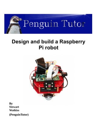
  • 1. Design and build a Raspberry Pi robot By Stewart Watkiss (PenguinTutor)
  • 2. About this guide This is a guide to creating Ruby Robot. An inexpensive robot vehicle controlled by a Raspberry Pi computer. Copyright This guide is provided through a creative commons license - Attribution-ShareAlike 3.0 Unported. License details: http://creativecommons.org/licenses/by-sa/3.0/ About the author Stewart Watkiss graduated from The University of Hull, UK, with a masters degree in electronic engineering. Since then he has been working in the IT industry, including Linux and networking. Linux has been his passion for many years and he has gained certification at LPIC-2. He runs the website PenguinTutor.com providing information on learning Linux, electronics and the Raspberry Pi. After working on several projects with the Raspberry Pi, both on his own or with his children, he signed up as a STEM ambassador to pass some of his knowledge on to school children helping out at local schools. He has also been technical reviewer of the book “Learning Raspberry Pi with Linux”, published by Apress, and a volunteer guest writer for The MagPi free magazine.
  • 3. DRAFT Version Contents Table of Contents Contents................................................................................................................................................1 Introduction..........................................................................................................................................3 How to use this guide...........................................................................................................................3 Knowledge required.............................................................................................................................4 Design decisions...................................................................................................................................4 Creating a design specification.............................................................................................................4 Design specification for robot vehicle.............................................................................................5 Deciding on main components.............................................................................................................5 Magician chassis kit.............................................................................................................................7 Raspberry Pi.........................................................................................................................................8 Raspbian Linux operating system....................................................................................................9 Initial configuration of the Raspberry Pi............................................................................................10 Download the NOOBS image........................................................................................................10 Connect the Raspberry Pi for first time install...............................................................................11 A basic introduction to the Linux command line...........................................................................13 Connect the robot to an existing Wi-Fi network............................................................................15 Installing additional software on Linux.........................................................................................16 Create a Wi-Fi hotspot for the Raspberry Pi..................................................................................17 Check the dongle supports Wireless Access Point mode..........................................................17 Configure the static IP address..................................................................................................18 Configure the DHCP server......................................................................................................18 Configure the Wireless Access Point software..........................................................................20 Logging on to the Raspberry Pi using SSH..............................................................................21 Adding the Raspberry Pi to the robot chassis.....................................................................................25 Power for the Raspberry Pi and motors.........................................................................................25 Shared or separate power supplies.................................................................................................26 Pre-supplied power supply.............................................................................................................27 Connecting the power...............................................................................................................27 Connecting the breadboard to the Raspberry Pi GPIO.............................................................27 Electronic circuit................................................................................................................................30 H-Bridge motor controller.............................................................................................................30 H-Bridge using relays / transistors / FETS / ICs...........................................................................32 SN754410 quad half-H driver IC..............................................................................................33 GPIO ports.....................................................................................................................................35 Circuit diagram...................................................................................................................................37 Breadboard design..............................................................................................................................38 Creating a more permanent circuit (stripboard vs PCB)...........................................................40 Printed Circuit Board - RyanTeck PCB kit RTK-000-001........................................................40 With diodes or without diodes..................................................................................................42 Heatsink....................................................................................................................................43 Controlling the speed of the motors with PWM............................................................................43 Writing the software to make it work.................................................................................................44 1
  • 4. DRAFT Version Basic software design points..........................................................................................................45 Using the design to provide implementation details......................................................................45 Choosing the programming language.......................................................................................46 Getting started with Python...........................................................................................................46 Learning to program in Python......................................................................................................49 Programming the GPIO with Python.............................................................................................50 Remote control Python program....................................................................................................51 Testing the robot.................................................................................................................................53 Adding a camera.................................................................................................................................53 Using the camera...........................................................................................................................55 Developing the robot vehicle further..................................................................................................56 Remote control vs. autonomous robots..........................................................................................56 Adding additional sensors..................................................................................................................57 What is I2C and SPI?.....................................................................................................................57 What's next?........................................................................................................................................58 Appendix A – Shopping list................................................................................................................59 Appendix B – Software requirements specification...........................................................................60 Software requirements specification for Ruby Robot v1...............................................................60 Appendix C – Program listing robotcontrol.py..................................................................................62 Appendix D – Key codes for remote control program.......................................................................65 Glossary..............................................................................................................................................66 2
  • 5. DRAFT Version Introduction This project is designed as a way of learning physical computing (the combination of computer programming with electronic circuits) in a fun way. When first starting out with electronics then getting a LED to flash can be quite exciting, and getting it to respond to programming done on a computer is another big leap, but once you have mastered those skills then it can be easy to lose interest. What we need is something that is exciting, fun to make, something you can show off to friends. The next challenge is that it needs to be affordable. It needs to be within a reasonable price that children (or their parents) can pay for an educational toy; unfortunately for most of us this rules out Lego Mindstorms and many commercial robots. I therefore started looking for an inexpensive robot vehicle kit that could be used for others learning about robotics. The result was the Ruby Robot shown on the front cover. The reactions I have had when taking the robot out in public has shown that children do indeed get excited when they see a robot, especially when you let them have a go at controlling it using a mobile phone or tablet. This guide is a detailed guide intended for young makers, teachers, computing or STEM club leaders, or parents. How to use this guide The guide is designed to be worked through page by page following the instructions on your own Raspberry Pi and robot chassis. The commands are shown with a grey background that should be entered in to the Raspberry Pi, or that represent what the completed code should look like. You should also consider the different options highlighted (see the chapter on Design decisions) for opportunities to personalise your own robot vehicle. If you are already familiar with a particular topic or are more interested in other parts then it is fine to skip that section or to just focus on the actions in that section. At the end you will have a robot vehicle which is similar to the one described, but with your own personal characteristics. Hopefully you will also learn about the various aspects involved in the design and build of the robot and most importantly have fun in doing it. If you are going to create the robot then you are going to need some parts. I've created a parts list in Appendix A which should be enough to get started. You may want to add other things later, but this is enough to be starting with. 3
  • 6. DRAFT Version Knowledge required This project is designed for secondary school children or those studying further education. Some basic knowledge of the Raspberry Pi will be useful (http://www.penguintutor.com/raspberrypi/) or some experience of running Linux and the command line interface on another computer. I have included some more links to related websites within this guide, or you could learn from a Linux or Raspberry Pi book such as Learn Linux with Raspberry Pi published by Apress or through the MagPi magazine (http://www.themagpi.com/) . A very basic understanding of electronic circuit theory would also be useful. More advanced topics are explained in detail in this guide. An understanding of Python programming would also be an advantage. You don't need to know Python programming to create the robot, although will help with understanding the code works. You will need to know some programming if you want to make most of the suggested improvements so it is worth taking the time to learn Python. The robot can also be a used with younger children by skipping some of the theory and just configuring as per the guide. For example it is possible to build the robot and then program it without needing to understand any of the electronic circuitry. Design decisions Whilst it's possible to follow the exact same design as I put down here there are lots of opportunities to do things differently. The design of the robot should become part of the learning experience. This allows the designer, or engineer to use the correct term, to create a unique robot that is individual to them and perhaps one that is more appropriate to specific tasks. One of the reasons for using the magician robot chassis is that this is a versatile base that allows components to be mounted in any number of different ways. This allows a unique robot to be created. Some of the things to consider are direction of the robot, and the position of the Raspberry Pi, the electronic circuit and the batteries. There are no right and wrong ways to locate these, but there are often pros and cons depending upon the specific use. Some of these advantages and disadvantages may not become apparent until later in the project, but this is all part of the learning experience. I will explain some of the pros and cons in the relevant sections. Look out for the light- bulb sign as an opportunity to customise the design. Creating a design specification Before starting on any project then you need to know what you are going to make. This may seem obvious, but turning this into a written specification can help with decisions that need to be made 4
  • 7. DRAFT Version later on. The design specification should describe the aims of the project rather than the actual parts and devices to be used. You may already have an idea of how you will make the project, but as you list the specification you may think of other ideas. There is no need to include the software design at this stage, that will be covered later. The amount of detail you include in the design specification will depend upon the complexity of the project and who the intended audience is. If it's just for a simple project for a hobby then you can keep it fairly brief, but if you are going to be asking for someone to fund your project or will be providing a write-up as part of a school or college project then you may need to provide a more detailed specification. I have created a simple design specification for this project as it's an informal project that I created for myself. I have started with a brief summary and then provided a list of requirements. In some cases I have given some flexibility within the requirements (such as referring to a computing devices rather than a specific computer or model of phone that it should be controlled by), whereas some are more specific (such as maximum budget). Each specification should be something that can be tested to test that it is met. Most of the specification is mandatory, but I have also included a “nice to have” feature. Design specification for robot vehicle This aim of the project is to create a robot vehicle that can be controlled from a computer or mobile phone. This is being made as a fun project that can help demonstrate the principles involved in designing and building a project. The vehicle should be relatively cheap and simple to build so that it can be replicated by a school or college student. • It should be simple to make using tools available in a standard workshop. • Vehicle should be able to move around on an even floor (such as carpet or wooden floor). • It should be possible to control the vehicle using a computer or other computing device. • Maximum cost is £100 (excluding batteries and optional camera). • It should be able to have a camera mounted to take photos of the environment. ◦ Live view or video recording would be an advantage (not required). • It should provide some flexibility for adding additional features. • It should be self powered. • Communication should be wireless so that no cables are required connecting to the vehicle. • The vehicle should be small enough so that it can be taken to events to give demonstrations. Deciding on main components The decision for the main components can now be made based upon whether they meet the specification. Although all the factors were considered the two main requirements for determining 5
  • 8. DRAFT Version the main components were cost and that is should be simple to make with standard tools. Whilst I haven't included a list of available tools within the specification I have referred to tools used in a standard workshop, which means that standard screwdriver may be required, but it should not require a laser cutter or 3D printer which whilst becoming more popular is not found in your typical workshop. There is potentially a grey area in between, such as whether a solder iron is available, which is an example of something you may need to clarify when working on a design. You may need to go back to the project sponsor to ask them to confirm whether it is required (which in the case of a hobby project may be yourself). As you will see later for this project a soldering iron is not actually required although it can be useful, particularly when looking at expanding the project in future. Without a laser cutter then this is going to mean using a robot kit or creating one from hobby components. Of course if you do have access to some more specialist tools then you have more flexibility in your design which would allow you to make a truly custom robot. The two main components that were decided upon were the Magician Robot Chassis for the body and wheels, with a Raspberry Pi to control it. Before finalising the design it is a good idea to consider alternatives. I was not able to find an alternative robot chassis that would fit in with the specification (mainly because of the cost aspect), although since starting there are some clones of the magician robot and at the time of writing there is a simpler single layer design looking for funding through Indiegogo. I also considered an Arduino compared with a Raspberry Pi for the processor. The decision to use the Raspberry Pi came down to supporting wireless control (it is possible with Arduino, but adds significant additional cost) and that programming a Raspberry Pi is generally considered easier than programming an Arduino. Having decided on the Raspberry Pi another decision to be made was what wireless method to use. The two most common ways of communicating using wireless are Wi-Fi (wireless networking) or Bluetooth. Neither of these are included in the Raspberry Pi, but can be added easily with a low cost USB adapter. Wi-Fi was chosen because of it's flexibility (it can also be used to configure the Raspberry Pi) and flexibility for sending images from the camera. In use I have found one disadvantage to using Wi-Fi, which is that it is prone to interference from other Wi-Fi networks. The robot uses a small USB dongle which does not have the signal strength to compete with strong wireless access points (WAP) if they are in the same room. I found that I had to keep the tablet I was connecting with close to the robot if it was using the same channel as a nearby WAP. The Wi-Fi configuration can be changed to use a different channel, which may need to be changed when taking the robot to a different site. More detailed decisions needed to be made later on in the design process, but having decided on this main components made the remaining decisions easier later on. 6
  • 9. DRAFT Version Magician chassis kit The magician chassis is a commercial robot vehicle kit available from several electronic and robot suppliers. The chassis appears to have been created with the Arduino in mind as the power connector from the battery pack matches with the Arduino power supply. This is something we will address later when we look at connecting the power supply to the Raspberry Pi. Instructions for assembling the kit are provided and are fairly easy to follow. When complete it should look like the photo below. If you follow the instructions provided with the magician robot chassis then the battery holder will be installed on the lower platform. The advantage of this is that it leaves plenty of space on the top to create the electronic circuits, but does mean having to unscrew the top of the robot chassis to be able to change the battery. You may prefer to have the battery on the top of the chassis so it is easier to swap batteries. An alternative is to swap the batteries for a rechargeable unit that can be charged when installed on the robot; this will however increase the cost so it has not been considered at this stage. For now I suggest you install the batteries on the bottom so that it is easier to create / modify the electronic circuit on the top of the chassis. Looking at the underside we can see how the robot vehicle will move around. There are two main drives wheels each of which is connected to it's own motor. There is then caster which is effectively a large ball-bearing which can move in any direction. Note that there are two discs on the motor shafts. These are not used at the moment, but are useful for being able to determine how far the vehicle has travelled. We will look at this later in the guide, for now take care not to lose these discs. 7
  • 10. DRAFT Version Now is a good idea to decide which direction is forward. The motors can be driven in either direction controlled by the electronic circuit and whilst there are advantages to having the driving wheels towards the front, particularly when travelling uphill, the motors provided are not going to be able to climb more than a very gentle slope so this is not much of an issue. In my initial version of the robot I have chosen the square end with the caster as the front, as the Raspberry Pi camera mount fits well on the straight edge. If you are looking to install sensors to determine if the robot reaches a wall you may instead prefer to use the curved edge as the front as there are more holes and space for mounting other sensors. If you change your mind then it's only a software change and it can drive in the opposite direction, but moving the position of the camera and Raspberry Pi is a little harder later. Raspberry Pi The robot chassis appears to have been designed for use with the Arduino, which is an open source programmable controller. Whilst the Arduino can control the motors and make simple decisions based on input sensors it does not have the processing capability as the Raspberry Pi, which is what we are using in this project. The Raspberry Pi is a small low cost computer designed specifically for education. It is based around an ARM processor which can run the open source Linux operating system and includes a GPIO (General Purpose Input Output) connector which can be used to interface to electronic circuits that can control the robot. The Raspberry Pi can also be connected to a camera which gives the robot the ability to see it's surroundings, or can be used to send images back to the operator. There are currently two different models of the Raspberry Pi. The model A is more basic with only one USB port, no wired Ethernet port and only 256Mb of memory, the model B includes additional features including an additional USB port, ethernet port and an increase to the amount of memory to 512MB. The model A is also less expensive. 8
  • 11. DRAFT Version The Raspberry Pi model A is recommended for this project as we won't be using a wired Ethernet port and the model A uses less power than the model B. The fact that the model A uses less power is useful when running on batteries. It can still run on a Raspberry Pi model B if you have one already, but you may need to consider a different power supply (see later). It's not possible for the Raspberry Pi to control the motors directly, so we are also going to need an electronic circuit. When designing a circuit it's a good idea to start by using a prototyping breadboard so we'll be adding a breadboard onto the robot chassis. The Raspberry Pi and breadboard can be installed in various different positions on the robot chassis. These can be installed on either the top or bottom plates of the chassis. For now I recommend using the top layer for the breadboard as it will make it easier to make any changes to the electronic circuit. You will need to consider the length of the cables required as well as any connectors on the Raspberry Pi that you would like to connect to. For example the camera comes with only a short ribbon cable to connect it to the Raspberry Pi, which is the reason I placed the Raspberry Pi close to the camera. I also put the Raspberry Pi with the GPIO connector closest to the breadboard so that only a short lead is required to connect to the breadboard. If you are going to be using a Wi-Fi dongle you need to ensure there is space near the USB ports for the dongle (such as by having the USB port point towards the side or the chassis) and if you want to add a speaker (so the robot can speak) then you should ensure that there is space by the 3.5mm audio socket to plug in a speaker cable. Finally whilst you won't be connecting the robot directly to a TV or monitor when it's in use it may be a good idea to leave space near the HDMI connector to be able to connect a screen when doing the initial set-up. Access to the HDMI port is not actually required as the set-up can be done on a different Raspberry Pi / computer or the Raspberry Pi could be temporarily disconnected when a new image is created. Raspbian Linux operating system The recommended operating system to run on the Raspberry Pi is Raspbian Linux. This is a distribution specifically created for the Raspberry Pi based upon Debian Linux. It can be purchased pre-installed on a SD card from the main suppliers (look for recent version of NOOBs SD cards), or can be downloaded from the Raspberry Pi website for install onto an SD card http://www.raspberrypi.org/downloads . Linux is a free open source operating system. It is free for anyone to use and its source code is available. Much of the software within the distribution is provided under the GPL (GNU General Public License) which means that if you modify and share the code then you need to make your modifications available under the same conditions. If you are familiar with other operating systems such as Windows, then you will find the Linux graphical desktop (sometimes referred to as a GUI – Graphical User Interface) familiar. It has a 9
  • 12. DRAFT Version look and feel more reminiscent of older versions, which is due to the low specification processor needing a leaner operating system. Modern Linux distributions running on a powerful computer provide a more feature rich experience. One thing that is different to some other operating systems is that you can run the full operating system without needing to have a graphical environment loaded and you can run commands on the computer remotely using the command line. This may be a little strange for those used to clicking on icons, but provides a lot of control and is very powerful. It is particularly useful in projects such as this robot where we can control and program the robot without needing to connect it to a monitor or TV. It may be useful to spend some time getting familiar with Linux before embarking on the rest of this project. To find out more about the Linux operating system see http://www.penguintutor.com/linux/about-linux or one of the many guides on Linux or the Raspberry Pi. Initial configuration of the Raspberry Pi We will need to make some configuration changes to the Raspberry Pi configuration to allow us to use certain features. Download the NOOBS image In this section we will set-up the Raspberry Pi with the Raspbian operating system. If you are already familiar with the Raspberry Pi and have set-up the operating system then you can skip this section, but ensure you read the section on creating a Wi-Fi hotspot if you would like to be able to control the robot outside of the range of your home wireless network. For this project we will be using the Raspbian operating system. This is easiest to install using the NOOBS software image. You can purchase an SD card with the operating system pre-loaded or you can download the software for free and install it onto a standard SD card. I assume you have an existing SD card and will be downloading the image from the Internet. You will need a 4GB SD card (or micro-SD card in an SD adapter). If it is a new pre-formatted card then you should be able to use it as it is, but otherwise you should format the card using the SD card association's formatting tool: https://www.sdcard.org/downloads/formatter_4/ Formatting the card and running the NOOBs initial configuration will delete all the data on the SD card. Make sure you have made a copy of any data you want to keep before formatting the card. 10
  • 13. DRAFT Version Download the NOOBS image from the Raspberry Pi website: http://www.raspberrypi.org/downloads You need to select the standard NOOBS image rather than the Lite version (especially if you are using a model A which has no ethernet port). The image is over 1GB in size and is usually quicker to download using a torrent client, although there is a standard web link on the website as well. This guide is based on NOOBs version 1.3.2, although it should work for future versions as well. Once you have downloaded the file (it should have a file ending with .zip) you should extract the files and copy all the files from the zip to the SD card. Note: Ensure you copy the contents from inside the zip file – not the zip file itself. Connect the Raspberry Pi for first time install The easiest way to perform the initial configuration of the Raspberry Pi is to connect it temporarily to a TV or screen and keyboard. The Raspberry Pi can be connected to a TV using a standard HDMI cable, or if you have a monitor that has a DVI connector then you can connect it to that using a HDMI to DVI connector. Alternatively you can use the RCA composite connector to connect to an analogue TV; if using an analogue TV you will need to press a button during start-up so that it knows to use the RCA connector (press 3 for PAL as used in most of Europe or 4 for NTSC used in the USA). Your SD card should be inserted in the slot on the Raspberry Pi and a keyboard in the USB port. The initial configuration can be performed with just a keyboard which is good as we don't have enough USB ports on the Model A to connect a mouse as well. If you do want to use a mouse then you may need to use a USB hub. Finally insert a micro-USB power supply (used for most mobile phones) into the power socket and the NOOBS first start screen will appear on the screen. Choose to install the Raspbian operating system which is the recommended choice (press space) and then press i to start the install. It will take a while to repartition the SD card and install the operating system, after which it will restart with the Linux operating system. 11
  • 14. DRAFT Version There is some useful information displayed on the screen during the install, but don't worry if you miss any of the messages as this guide provides all the instructions for this particular set-up. Installing an operating system is often a good time to put the kettle on and get yourself a hot drink ready for when we get to the fun stuff. After the operating system boots for the first time the Raspberry Pi Software Configuration Tool will run (raspi-config). This tool gives a menu which makes it easier to configure some features of the operating system. I have listed some of the useful options below: Change User Password – Recommended to keep your system secure. The default username is pi and the password is raspberry. Enable Boot to Desktop – This is not required for a robot. It provides a graphical interface similar to that used by Windows Internationalisation Options – If you are in the UK then you don't normally need to change this. If you are in a different country or use a non-UK keyboard then you may want to change this to your local country. Enable Camera – This is required if you want to use the Raspberry Pi camera module Advanced Options – You can reduce the memory allocation to 16MB and provide a unique hostname for your Raspberry Pi. It is normally a good idea to check for an updated version as well, but that is only possible when connected to the Internet. Once you have made the changes choose finish and then reboot the Raspberry Pi. 12
  • 15. DRAFT Version If you need to make any changes to these in future you can launch the configuration tool by running sudo raspi-config A basic introduction to the Linux command line Once the operating system has been installed you should see a lot of text scroll across the screen. Do not be alarmed this is the normal behaviour. Most computers will also generate similar messages, but it is often hidden from the user to make a computer appear to be more user friendly. In fact this is often hidden when using Linux on a regular PC, but for the Raspberry Pi it is useful for those learning computing to see what is happening behind the scenes as well as being a useful tool when things go wrong. You may expect to see a graphical screen with icons that you can click, but we won't here. The Raspberry Pi does have a graphical user interface (similar to windows), but we won't be using it in this as we will be disconnecting the screen shortly. This is why I said not to enable the “Boot to Desktop” option during the raspi-config. Instead we will be telling the computer what to do by issuing instructions through a text based interface called the shell. This is often referred to as using the command line. It may not feel as friendly as a graphical screen but it's not quite as scary as it first seems and is in fact a very powerful way to communicate with a computer. For now you can ignore the text from the computer starting up and wait until you get the login prompt. Enter the username pi next to login: and press enter and then enter the password which will be raspberry unless you changed it earlier. Note that you won't see any characters when you enter the password, which is a security feature to prevent others from seeing your password. When logged in you will see a line of text ending with a dollar symbol ($) at the bottom of the screen. This line will be prefixed with some more information about the computer you are on. On my robot it looks like: pi@ruby-robot:~$ The $ symbol is call the command prompt and indicates that the shell (the interface to the computer) is ready for input. The text at the left shows the username you are logged in as, the hostname of the computer and the current directory that you are in. Another prompt you may see ends with the hash symbol (#) instead of the $. The # denotes that you are running with super-user privileges and you need to take additional care when running commands. If you have used the Windows command mode (cmd.exe) then you will notice some similarities, although there are some differences. 13
  • 16. DRAFT Version To see what directory (sometimes these are referred to as folders on Windows) you are currently in use the pwd (print working directory) command. Just type pwd and hit enter: pi@ruby-robot:~$ pwd /home/pi pi@ruby-robot:~$ The directory is shown on the next line - /home/pi and then it returns a prompt waiting for the next command. You may notice that the directory separators '/' go the opposite way to what you see on Windows; Unix (on which Linux is based) was around long before DOS (on which Windows directory seperator is based). The /home/pi directory is the home directory for the user pi. The home directory also has a special character '~' which is what we saw in the command prompt. Just note that when you use ~ in a directory name then you can replace it with /home/username . You can list the files in the current directory with the ls command, and you can move around into different directories using the cd (change directory command). To run a program you just enter it's name on the command line followed by enter. You can often enter instructions (command options) to the command after the command name. nano test.txt This will run the nano text editor. It will edit the file test.txt and if the file doesn't already exist it will create it. The nano editor is one of the easiest editors to use on the command line and so we will use it later. To save the contents of the editor to the current file use <Ctrl> O (hold down the Ctrl key whilst pressing the O key). Then use <Ctrl> X to exit. You can see the available instructions at the bottom of the editor page. GNU nano 2.2.6 File: test.txt [ Read 0 lines ] ^G Get Help ^O WriteOut ^R Read File ^Y Prev Page ^K Cut Text ^C Cur Pos ^X Exit ^J Justify ^W Where Is ^V Next Page ^U UnCut Text^T To Spell To learn more about the Linux command line see: 14
  • 17. DRAFT Version http://www.penguintutor.com/linux/ Connect the robot to an existing Wi-Fi network Whilst we could configure the Raspberry Pi to an existing home wireless network this will mean that if you take the robot away from home then it will not be possible to communicate with the robot. We will therefore set-up the Raspberry Pi as a Wi-Fi hotspot. To do this we need to install some additional software and for that we need a working network connection. If you have a model B with an Ethernet port and have a wired network router handy then you can connect the network direct to a router and install the packages that way (in which case jump to the next section on installing additional software), but if you are using a model A then we need to connect to a wireless network to download the software. First we need to edit the /etc/interfaces file which tells the operating system how to configure the network interfaces. The example I have used is based upon the nano editor. Run the command: sudo nano /etc/network/interfaces Note that I have prefixed this with sudo, which allows us to edit the file as a system administrator (root user). If you don't add sudo then you will get a warning “No write permission” in nano and you will not be able to save the file. Look for the entry iface wlan0 inet dhcp and add the following entries below it: wireless-mode managed wireless-essid <SSID> wireless-key <Passphrase> Replace <SSID> with the name of your wireless network and <Security key> with your network security passphrase. If you have not changed these and have a wireless router supplied by your broadband provider then they are most likely shown on the rear of your wireless router. The following shows an example of what to look for (these are made up based on an example Virgin Media router): Wireless SSID: virginmedia0123456 Wireless Key (Passphrase): dh3892jhndkl You can restart the networking, but I recommend rebooting at this stage to make sure it comes up 15
  • 18. DRAFT Version from a reboot. sudo reboot Installing additional software on Linux Assuming you now have a working Internet connection (see previous section on configuring wireless networking first) we can now update the software on the Raspberry Pi and add the packages we will need later. This needs to be done prior to configuring the Raspberry Pi as a wireless hotspot as we will be creating an independent network and so will lose our connection to the Internet. There is a Raspberry Pi App store which is based on a similar concept to mobile phone App stores, but there is also a software installer for Linux that uses a similar way of installing software over the Internet which was in use long before the App Stores. We will be using the apt-get tool to install software, which installs software that is supplied in the Debian package format. This is used for the main operating system (and we will use this to upgrade any updated files) as well as numerous software packages ranging from simple tools (mostly what we are installing here) to a fully fledged software package such as an office suite or photo editor. The software installed through apt-get is free and does not install adware on your computer. First we will update the list of software to find any changes and then install any changes to the operating system. This is done with the following two commands: sudo apt-get update sudo apt-get dist-upgrade This may take a while to run as it downloads any updates to the Raspbian operating system since the NOOBS image was created. Now that the system is up to date we can install the additional software. These can be installed in a single command, but I have put these down separately with a short explanation. We will be configuring these later, for now just install them whilst you still have network connection. The iw command will be used to query the wireless network interface. It's not actually required, but can help to spot potential problems with the dongle. sudo apt-get install iw 16
  • 19. DRAFT Version The hostapd is the software used to configure the computer as a wireless access point. It is a daemon which runs in the background to handle the wireless networking. sudo apt-get install hostapd To provide an IP address to the clients that connect we use DHCP. This can be run on the Raspberry Pi through the ISC DHCP server. sudo apt-get install isc-dhcp-server Note that whilst installing the dhcp server you may get an error saying that it has not been possible to start the dhcp server. You can ignore the warning for now, once we have configured the server it should start correctly. If there is any more software that you know you will need later then you can add it now as it will be harder to install later when we have reconfigured the networking. Create a Wi-Fi hotspot for the Raspberry Pi We can now reconfigure the Raspberry Pi as a Wireless hotspot so that we can connect to the robot from anywhere even if there is no other wireless network signal. This needs a number of different networking services to work. I will briefly explain each one as I add it, but it would be too much to explain each in detail in this guide. More information about Networking on Linux is available from: http://www.penguintutor.com/linux/#Networking Check the dongle supports Wireless Access Point mode First we can check if the wireless dongle supports Access Point mode (WAP). The majority of dongles do, but it saves spending time trying to configure this on the robot if the dongle doesn't support it. Run: iw list Within the Supported interface modes look for an entry for AP eg. Supported interface modes: * IBSS * managed * AP * AP/VLAN * WDS 17
  • 20. DRAFT Version * monitor * mesh point As long as that is included then the dongle can act as an access point. If there is too much information to see you can view the output through the less command. iw list | less Use the cursor keys to move around and q to quit when you have finished. Configure the static IP address We now need to reconfigure the network with a static IP address. Whilst it is possible to use the same IP address range as you have on your existing Wi-Fi network we can avoid some potential problems by using a different network range. This will help if you try and connect from a computer that is connected to your local network (using wired ethernet) and you are connecting to the robot using wireless. There are a number of network ranges that are reserved for local use (chances are that your normally wireless network uses one of these ranges). I have chosen the network 10.5.5.0 / 24 as this is less commonly used. We will set the robot to 10.5.5.1 which is the first usable IP address in that range. sudo nano /etc/network/interfaces Find the entry for the wireless LAN which we changed previously (wlan0). Remove the iface wlan0 entry and the wireless network information and replace with: iface wlan0 inet static address 10.5.5.1 netmask 255.255.255.0 Configure the DHCP server IP addresses can be statically configured so that they don't change (as we need to configure on the robot), but most end users connect with a dynamic IP address which is allocated to the computer when it connects to the network. This is done using a protocol called DHCP (dynamic host configuration protocol). We can configure the Raspberry Pi as a DHCP server so that it can provide the IP address for the clients to use. 18
  • 21. DRAFT Version This is configured in the /etc/dhcp/dhcpd.conf file sudo nano /etc/dhcp/dhcpd.conf We will be using the IP address of the robot to connect to it so we don't need the domain name entries in the dhcpd.conf file. Comment out the domain-name entries by prefixing each line with a '#' as below. #option domain-name "example.org"; #option domain-name-servers ns1.example.org, ns2.example.org; Make this the authoritative DHCP server by removing the # character in front of the authoritative keyword as below: # If this DHCP server is the official DHCP server for the local # network, the authoritative directive should be uncommented. authoritative; Edit the section titled “#A slightly different configuration for an internal subnet” so that it looks like this: # A slightly different configuration for an internal subnet. subnet 10.5.5.0 netmask 255.255.255.0 { range 10.5.5.100 10.5.5.150; option routers 10.5.5.1; option broadcast-address 10.5.5.255; default-lease-time 600; max-lease-time 7200; } This will allocate addresses between 10.5.5.100 and 10.5.5.150. Save and exit from the file. Now edit the default start script to set the interface. sudo nano /etc/default/isc_dhcp_server change the interfaces to: INTERFACES=”wlan0” The dhcp server is now configured. We could start it manually now, but instead we will reboot the Raspberry Pi when we have completed the rest of the steps. 19
  • 22. DRAFT Version Configure the Wireless Access Point software The configuration for the wireless access point should go into a new file /etc/hostapd/hostapd.conf This file doesn't currently exist, but if we try to edit a file that doesn't exist then nano is smart enough to realise it needs to create a new file. sudo nano /etc/hostapd/hostapd.conf Add the following – inserting your own wireless SSID and passphrase as appropriate. # Host access point config file # device name interface=wlan0 # Driver interface driver=hostap # SSID for the network ssid=<SSID> # set appropriate country parameters (maybe required for regulatory reasons) country_code=GB # Operation mode - for 802.11n still use g to indicate using same band as g devices hw_mode=g # set channel - channel=0 for Automatic Channel Select channel=0 # mac address access list - 0 = accept unless in deny macaddr_acl=0 # Use shared key authentication auth_algs=1 # Enable WPA2 wpa=2 # set passphrase wpa_passphrase=<passphrase> # Use WPA PSK wpa_key_mgmt=WPA-PSK # Pairwise cipher for WPA (v1) wpa_pairwise=TKIP # Pairwise cipher for RSN/WPA2 20
  • 23. DRAFT Version rsn_pairwise=CCMP Now add the configuration file to the hostapd startup file. sudo nano /etc/default/hostapd Add entry: DAEMON_CONF=”/etc/hostapd/hostapd.conf” Now reboot the Raspberry Pi. You should now be able to see your new wireless network with a computer or mobile phone and connect to it using the appropriate passphrase. Remember you will not have any Internet access. The only computer you will be able to connect to is the robot Raspberry Pi at address 10.5.5.1 Logging on to the Raspberry Pi using SSH Now that the Raspberry Pi has a working network connection it should be possible to remove the connections to the screen and keyboard and continue the rest of the configuration over the network. The usual way of connecting to a Linux computer is using SSH. This uses a text based client that will run a shell on the “server” (see What is a server? below). It allows you to run commands in the same way as we did for the configuration above, but across the network instead of needing to be on the Raspberry Pi. SSH is an encrypted protocol so that it is not possible for others on the network to see what commands are being issued and more importantly the username and password used to login. You can get an ssh client for most computers, including tablets and smart phones. What is a server? You may think of a server as being a computer sat in a dedicated data centre hosting a website. Whilst that can be the case, any computer can actually act as a server for certain functions, even a desktop computer or a mobile phone. When we talk about a server it is whichever computer is running the code that allows a client (the opposite of a server) to connect to it. The Raspbian operating system includes the OpenSSH server which is enabled by default to allow a client to connect to the Raspberry Pi. SSH has a lot more functionality than we are using here. SSH can be configured to use key based authentication providing a secure way of connecting from one computer to another without needing to login manually (which is useful for automation). SSH can also be used to create tunnels to direct network traffic over an encrypted session over an insecure network. For more details see: http://www.openssh.com/ 21
  • 24. DRAFT Version Using SSH from a linux or MAC OS X computer On Linux (including the Raspberry Pi), and Mac OS X you can run ssh from a terminal shell. The terminal shell may have a different name depending upon the Linux distribution, the most common names are: Terminal; LXTerminal or Konsole. The client is normally OpenSSH which is run from the shell. There are alternative ssh clients including PuTTY which is a GUI based application, but still uses the same text based shell for running commands on the remote computer. See the next section on SSH in Windows if you'd like instructions for PuTTY. Once in the terminal shell you can issue the ssh command, which should be followed by the username you want to connect as, an @ sign and the IP address of the computer to connect to. You can see this in action below. stewart@linux-pc:~$ ssh pi@10.5.5.1 The authenticity of host '10.5.5.1 (10.5.5.1)' can't be established. RSA key fingerprint is 09:b4:41:4c:b5:c1:4a:94:62:54:e3:b0:5f:78:71:d2. Are you sure you want to continue connecting (yes/no)? yes Warning: Permanently added '10.5.5.1' (RSA) to the list of known hosts. pi@192.168.0.11's password: The programs included with the Debian GNU/Linux system are free software; the exact distribution terms for each program are described in the individual files in /usr/share/doc/*/copyright. Debian GNU/Linux comes with ABSOLUTELY NO WARRANTY, to the extent permitted by applicable law. pi@ruby-robot:~$ I started out logged in as username stewart on my Linux computer linux-pc. You can tell the computer I am logged in as in the prompt (before the $ sign). From this computer I entered the command “ssh pi@10.5.5.1” which connected to the robot Raspberry Pi. This is the first time it has connected to this computer and so it provides some details about the computer so you can decide if that is the correct computer. If you want to check you are connecting to the correct computer then you can run the “ssh-keygen -l” command when physically connected to the computer. You will need to provide the appropriate file where SSH has stored the key. In reality if this is your local network and you know this is a computer you have not connected to before then you can just accept the connection using 'yes'. If in future you get a warning that the key has changed then you should take extra care in case someone is masquerading as your computer, although if you have re-installed the operating system that will also generate the same warning. It then asks for the password of the computer I was connecting to. Once entered correctly it shows the standard login banner for that computer. 22
  • 25. DRAFT Version You can now see from the prompt that I am now logged in to a different computer – username pi on computer ruby-robot. From now on any commands entered will be run on the remote computer “ruby-robot” and not the computer that I am typing on. When using ssh get used to looking at the computer name on the command prompt before issuing a command to make sure you are on the correct computer. Using SSH from a Windows computer Unlike other operating systems Microsoft Windows does not normally include an ssh client. There are a number of free ssh clients for Windows. PuTTY is one of the most popular clients. It is a graphical application, but still provides the same text based interface that is used by the standard OpenSSH client used in Linux. You can download it from: http://www.chiark.greenend.org.uk/~sgtatham/putty/ You can either download the executable file putty.exe, which can be saved onto your local computer, or as an installer which includes a file transfer client and other tools. When you run PuTTY you will be presented with the following startup screen. You can enter the IP address of the Raspberry Pi 10.5.5.1 in “Host Name (or IP address)”. The port can be left at the default of 22 and then click open. 23
  • 26. DRAFT Version This is the first time PuTTY has connected to this computer and so it provides a security alert with some details about the computer so you can decide if that is the correct computer. If you want to check you are connecting to the correct computer then you can run the “ssh-keygen -l” command when physically connected to the Raspberry Pi. You will need to provide the appropriate file where SSH has stored the key. In reality if this is your local network and you know this is a computer you have not connected to before then you can just accept the connection using 'Yes'. If in future you get a warning that the key has changed then you should take extra care in case someone is masquerading as your computer, although if you have re-installed the computer that will also generate the same warning. 24
  • 27. DRAFT Version You will now be presented with a login prompt where you can login with the username and password for the Raspberry Pi. After logging on any commands entered will be run on the remote computer “ruby-robot” and not the computer that I am typing on. When using ssh get used to looking at the computer name on the command prompt before issuing a command to make sure you are on the right computer first. Adding the Raspberry Pi to the robot chassis We now have the robot chassis built and Raspberry Pi configured so that we can connect to it over the network; it's now time to put the two together. The Raspberry Pi can be installed anywhere on the chassis. The key things to consider are the length of the camera cable (if using a Raspberry Pi camera) and the cable from the GPIO to the breadboard. In the robot vehicle shown the Raspberry Pi is at the front (or at least what I designated as the front) so that it could use the standard cables. If you would rather install it elsewhere then you may need to get longer cables. There are two holes on the Raspberry Pi board that be used to secure it using the PCB stands provided with the robot chassis. Power for the Raspberry Pi and motors The Raspberry Pi needs a power supply of 5V. This is the standard supply from a USB socket and for the power used for most modern mobile phones. The tolerance of the supply is ± 0.25V which means that the power supply should be between 4.75V and 5.25V. If the supply falls below 4.75V then it is likely to have problems, typically the USB devices stop working first, but other problems may occur (such as unexpected reboots). More than 5.25V and there is a risk of damage to the Raspberry Pi. The power supply needs to be able to supply a running current of around 300mA for the model A or 25
  • 28. DRAFT Version 700mA if using a model B. This is the main reason that the model A is better suited for this project, to reduce the load on the power supply. The motors supplied with the magician chassis are designed for a maximum of 6V. If you factor in the voltage drop within the electronic circuit then ideally it should have a higher power supply. Whilst we haven't decided on how to switch the motors yet you could consider about 1 volt voltage drop in the circuitry. So we should therefore be looking for a power supply of about 7V, which is required to run the motors at full power. Through testing I have found that the particular motors I have will run on a 5V supply even with our control circuitry. If using 5V the motors will be running with less power than if the supply to the motors is 6V, but in tests it was shown to be sufficient for moving the robot around on a relatively flat surface. Shared or separate power supplies As the power requirements for the motors and the Raspberry Pi differ then ideally they should either have separate power supplies, or a single power supply that is regulated down to the supply voltage of the Raspberry Pi. Doing so would also with preventing noise on the power supply which will be generated when the motor is turned on and off. To add a second supply (or to upgrade the power supply with an additional regulator circuit) could add significant additional cost. If this was a commercial project, and in particular if this had a mission critical application then it would be important to work within the specification of all the components. In fact for mission critical equipment then it is common to over-engineer a solution to make sure it will continue to perform beyond it's designed capability. This could be achieved using two separate power supplies: a dedicated USB supply for the Raspberry Pi and a higher voltage power supply capable of providing the full voltage for the motors. One of the main criteria was for the cost to be kept low and as an educational and demonstration vehicle there is no risk if it doesn't perform correctly. Obviously we would still like this to be as reliable as possible as it can be embarrassing when trying to demonstrate something that doesn't work. Testing was performed to to ensure that the motors did work at a reduced voltage and this was considered adequate for this project. If you come across any power related issues when building your own (or unexplained problems with the Raspberry Pi) then you may need to to add a separate power supply for the Raspberry Pi. It is possible to test whether power is the cause of problems by using a temporary power supply for the Raspberry Pi to see if it eliminates the problem. 26
  • 29. DRAFT Version Pre-supplied power supply The chassis kit comes with a battery holder designed for 4 x AA batteries. The nominal voltage for a standard AA battery is 1.5V which gives 6V for the 4 batteries in series, but rechargeable batteries (NiCd / NiMH) have a lower nominal voltage of 1.2V which gives 4.8V. The actual voltage of the batteries will depend upon charge and how much current is being drawn from them. In my experience rechargeable NiMH batteries work well with the robot. I expect standard Alkaline batteries will work as well, but that would be at your own risk as you will be applying more than the recommended voltage to the Raspberry Pi and any connected USB devices. I recommend using high-capacity NiMH batteries in the supplied battery holder. You may wish to consider other battery types, such as high capacity batteries designed for remote control cars (which could be used with a regulator to power the Raspberry Pi and motors) or mobile phone top-up batteries (to provide a second power supply dedicated to the Raspberry Pi). The maximum supply voltage for the Raspberry Pi should not be exceeded if using a non USB based power source. Connecting the power Power is normally provided to the Raspberry Pi using a micro-USB connector, however the power connector on the battery holder is provided as 2.5mm DC plug. An alternative way to connect the power supply to the Raspberry Pi is through the GPIO connector. I have used a 2.5mm DC socket to terminal connector which is then wired to the breadboard used for the electronic circuit. The power is then connected to the Raspberry Pi through the GPIO port. Care must be taken when connecting power through the GPIO port as it bypasses the poly-fuse included used to protect the power coming from the micro-USB port. Using 4 x AA batteries should work fine with this set-up, but additional protection should be considered if using different batteries. Connecting the breadboard to the Raspberry Pi GPIO The GPIO port on the Raspberry Pi is a 26-way male header connector on the edge of the board. 27
  • 30. DRAFT Version The individual pins can be connected direct to the breadboard using male-to-female jumper leads, which is the cheapest way, but I chose to use a Raspberry Pi breakout cobbler board. The cobbler board is a small PCB with a 26-way connector that matches the one on the Raspberry Pi GPIO. A ribbon cable is used to connect between the GPIO on the Raspberry Pi and the cobbler. It is important to connect the ribbon cable the correct way around, on the cobbler there is normally a gap in the connector housing to ensure the cable can only be inserted one way around, but the Raspberry Pi GPIO does not have that luxury. Pin 1 is marked on both the Raspberry Pi and the cobbler and the ribbon cable should be positioned so that wire number 1 (normally coloured red) aligns with pin 1 at both ends. The cobbler is normally provided as a kit that you need to solder yourself. Soldering is a useful skill for creating electronic projects, but you could ask someone solder these for you if you don't want to learn soldering just yet. Soldering is not difficult, but it does have an element of risk due to the hot element which will be at several hundred degrees Celsius. It is important to ensure that the soldering iron is stored on a proper stand and always treated with appropriate care. Children should only use a soldering iron when under appropriate supervision from a competent adult. One of the advantages of the cobbler is that it makes it easier to remove the Raspberry Pi (which I found useful when sharing a Raspberry Pi between the robot and a Code Club I was running), but also that it makes it easier to see the pin designation on the breadboard. Since creating my robot RasPi.TV has released some new expansion boards for the Raspberry Pi, which includes a Breakout board that is an alternative to using the cobbler. It works almost in reverse to the cobbler in that it puts the breakout pins on an expansion board on the Raspberry Pi GPIO rather than on the breadboard. An advantage of this is that it still makes it easy to see the port labelling and disconnect from the Raspberry Pi, but doesn't use up space on the breadboard. 28
  • 31. DRAFT Version Below is a diagram of the GPIO connector showing its different pin references. The numbers in the corner are the port numbers. These are numbered 1 to 26, numbered vertically from the top right. Where there are two GPIO numbers this refers to a change between revision one and two of the Raspberry Pi, where a second reference is shown it refers to an alternate usage of the pin (such as I2 C, SPI or serial communication). To provide the power supply through the GPIO then any of the Gnd and 5V0 pins can be used. In this case I have used pin 2 for the 5V supply and pin 24 for the ground connection. I first connected the power supply to the power rails on the breadboard and then connected from those to the appropriate pins on the GPIO port. There is no input protection for any power supply connected directly through the GPIO port. Please read the warnings regarding the choice of power supply, or consider adding your own fuse protection prior to the power supply connecting to the Raspberry Pi. A safer alternative to connecting through the GPIO is to cut up an existing micro-usb cable and connect the red wire to the 5V supply and the black wire to Gnd. The white and green wires are for data and are not connected on the Raspberry Pi so can be cut off. If using the micro-usb connector the Gnd connection should still be connected on the GPIO connector, but the 5V one should not. Note that the power supply ports are labelled as 5V0, which really means 5.0V (or five volts). This is how electronic circuits are usually labelled to avoid ambiguity, especially when using small writing. For example we also have some ports labelled as 3V3 which provide a 3.3V feed from the Raspberry Pi. Written in small writing the decimal point is barely visible and would be easy to miss (is it 33V or 3.3V? - quite a difference!). A similar convention is used for resistors where a 100Ω (one hundred ohm) resistor would be labelled as 100R and a 2.2KΩ resistor would be labelled as 2K2. Once the battery is connected it should be possible to connect the batteries and power up the Raspberry Pi. Do not be tempted to connect the motors directly to the GPIO as it can damage the 29 GPIO connector 1 3V3 GPIO0/2 SDA GPIO1/3 SCL GPIO4 CPCLK0 Gnd GPIO17 GPIO21/27 GPIO22 3V3 GPIO10 MOSI GPIO9 MISO GPIO11 SCLK Gnd 5V0 5V0 Gnd GPIO14 TXD GPIO15 RXD GPIO18 PCM_CLK Gnd GPIO23 GPIO24 Gnd GPIO25 GPIO8 CE0 GPIO7 CE1 2 25 26
  • 32. DRAFT Version Raspberry Pi. Electronic circuit Now that we are able to power the Raspberry Pi from the batteries we can look at the electronics required to drive the motors. As I have already stated it is not possible to power the motors directly from the GPIO ports. Firstly the GPIO can only supply 3.3V output whereas the motor is designed for 6V, but also the amount of current that can be supplied through the GPIO would be only a fraction of what we actually need to run the motor. The GPIO ports from the Raspberry Pi connect direct to pins on the processor. There is no protection to protect the processor against faulty wiring or too high a voltage on the pins. The GPIO ports are designed for 3.3V operation and connecting these directly to a 5V power source could permanently damage the Raspberry Pi. H-Bridge motor controller Before I get to the actual circuit (which is pretty simple) here is some of the theory of how a H- bridge motor controller works. The motors supplied are basic DC motors with built in gears. These kind of motors have only two wires which are for the power. The direction of the motor is determined by the direction of the current through the motor, so by reversing the positive and negative supply we can make the motors change direction. The H-bridge configuration is a common way to change the direction of the power supply. The h- bridge is named as it is shaped a little like a letter H and uses two pairs of switches that need to be switched together. It is easiest explained using diagrams. The switch pairs are diagonally opposite to each other. Each pair of switches need to be closed at the same time. So on the diagrams below S1 and S4 form one pair and S2 and S3 the other pair. This is the H-bridge in it's off position. All four switches are turned off and no power is provided to the motor. 30
  • 33. DRAFT Version When S1 and S4 are closed the positive supply goes to the left of the motor and the negative to the right. The motor will then work in one direction. To change the direction switches S1 and S4 need to be opened and then S2 and S3 closed. The positive supply is now provided to the right of the motor and the negative to the left, so the motor 31 M +V Gnd S1 S2 S3 S4 M +V Gnd S1 S2 S3 S4 + -
  • 34. DRAFT Version will now turn in the opposite direction. It is important that S1 and S3 are never closed at the same time and the same with S2 and S4. Switching these on together would create a short circuit across the power supply. H-Bridge using relays / transistors / FETS / ICs The H-bridge circuit can be created using a variety of different components. A relay is perhaps the easiest to understand as the relay is a physical switch which replaces each of the switches shown. It also has the advantage that very large loads can be switched if appropriately sized relays are used, or if the load is smaller a compact reed relay can be used. The two disadvantages are that some kind of buffer is required and the lack of speed control. Buffers are required as relays can need a significant amount of current to activate and even a small reed relay will need more than the GPIO can provide. In the case of a small relay a simple transistor switch could be used to activate the relay, or this can be done using a PiFace digital (see http://www.piface.org.uk/ for more details about PiFace). The other disadvantage, which is a bigger problem, is the lack of speed control. The speed of a DC motor depends upon the strength of the magnetic field which is created by the current flowing 32 M +V Gnd S1 S2 S3 S4 - +
  • 35. DRAFT Version through the motor coils. The strength of the magnetic field can be controlled by changing the voltage at the motor. Using an on/off switch will mean that the voltage and current to the motor is fixed (although it could be altered using additional circuitry to change the voltage that is provided as the Vcc of the H-bridge). The technique we will be using to change the speed of the motor is based upon rapidly turning the switches on and off which is not possible with relays that have a slow switching speed. The next suggestion is using either transistors or FETs (Field Effect Transistors). These are discrete components that act as amplifiers by switching a current through a pair of terminals based upon a small current on a third terminal (or voltage input in the case of an FET). These can be used as electronic switches by providing them with an apprporiate input. Using transistors then S1 and S2 would be PNP transistor and S3 and S4 would be NPN transistors. A similar configuration is required for FETs where S1 and S2 would be P-channel FETs and S3 and S4 would be N-channel FETs. It can be a useful exercise to build a H-bridge using discrete transistors, but for the purposes of controlling the robot vehicle then I recommend using an existing integrated circuit or a Raspberry Pi expansion board. If creating a transistor / FET circuit then you need to ensure that the transistors are not switched in such a way as to cause a short circuit. The recommended way of creating the H-bridge is to use an existing integrated circuit (IC). These have the advantages of fast switching capability that is provided by an active transistor circuit, but with the convenience of this being in a single package. Another advantage is that the IC will normally be configured so as to not allow the switches to be turned on in a way that would cause a short circuit. The ICs normally do this by having a single in-signal for each half of the H-bridge to determine direction, with an enable signal to determine whether the motor should be on or not. One disadvantage of using an IC is that it cannot be used to control large motors. That is not an issue for this design. SN754410 quad half-H driver IC The use of an integrated circuit has clear advantages and makes the circuit for controlling the robot vehicle motors simple. The SN754410 IC has been chosen as it is inexpensive, widely available and is TTL compatible so it can be used directly with the 3.3V signals from the Raspberry Pi. data sheets are a useful source of information when designing electronic circuits. For an integrated circuit they will normally provide: an explanation about what the integrated circuit can be used for; the recommended voltages and operating conditions and often include example circuit diagrams of how they can be used. data sheets are normally created by the manufacturers and are often available through electronic component retailers or can be found through an Internet search. 33
  • 36. DRAFT Version This integrated circuit is a quad half-H driver which provides four modules. Combining two of these modules provides a single H-bridge circuit. We can therefore use one IC to control two motors. The PIN layout is shown below: The logical diagram shows how the four half-bridge modules can be configured as a pair of H- bridge controllers. To check that the IC is suitable we should refer to the data sheet available from the manufacturer (in this case Texas Instruments). According to the data sheet the IC can be used to switch up to 1A for supplies of 4.5V to 36V, and includes a separate power supply for the input to output. All inputs are compatible with TTL and CMOS logic with the 3.3V from the GPIO fitting within the input high range of between 2 and 5.5V. This shows it as being suitable for this install. 34
  • 37. DRAFT Version There are two different ways of using the input signals for the H-bridge controller. One way is to have a single output for the motor direction which is inverted between the two inputs, and then use the enable pin to turn the motor on and off. So for example if you had a high direction input that would go to input 1A and inverted low at input 2A and the opposite to change direction. This will just require two outputs from the Raspberry Pi, but would need an inverter to be added to the circuit. Or this could be implemented by having three outputs from the GPIO with one being inverted. The other option, which is the one we will use here, is to permanently enable the EN pin by connecting it to high and then using the two inputs to turn the motor on and off as well as to determine the direction. This is achieved by setting both 1A and 2A to low, which is the off state and then turning one of these high to turn the motor on and set the direction. GPIO ports There are 26 pins on the Raspberry Pi GPIO connector; of these pins 17 can be used as inputs or outputs for the Raspberry Pi. To control the motors we need four of these to be used as output pins. 35
  • 38. DRAFT Version Pin No. Designation Pin No. Designation 1 3V3 2 5V0 3 4 5V0 5 6 Gnd 7 8 9 Gnd 10 11 GPIO 17 12 13 GPIO 21/27 14 Gnd 15 GPIO 22 16 GPIO 23 17 3V3 18 GPIO 24 19 20 Gnd 21 22 GPIO 25 23 24 GPIO 8 25 Gnd 26 GPIO 0/2 SDA GPIO 1/3 SCL GPIO 4 CPCLK0 GPIO 14 TXD GPIO 15 RXD GPIO 18 PCM_CLK GPIO 10 MOSI GPIO 9 MSO GPIO 11 SCLK GPIO 7 CE1 Whilst any of the pins labelled as GPIO can be used there are some that reduce compatibility between different versions of the Raspberry Pi. This is due to an updated version of the Raspberry Pi Model B (known as revision 2) released around September 2012. Whilst it is possible to detect this in software and address the pins appropriately it is easier to avoid the pins that have changed GPIO port reference (as shown with a / in the GPIO references). If you would like to know what kind of Raspberry Pi you have then you can look at the physical board for the screw mounting holes (which were not included on revision 1.0 boards), or from Linux run 'cat /proc/cpuinfo'. The hardware revision number will be 2 or 3 for a revision 1 board (the latter without the troublesome USB fuses), revision 2 boards have a higher number. In the pin assignment list above there are also some ports that are used for specific purposes. For example pins 8 and 10 are used for serial communications (by default are used as debugging console) and there are several of the pins that are used for SPI or I2 C connections. The ports used for SPI or I2 C can still function as standard GPIO ports, but they are useful for adding additional sensors and outputs. 36
  • 39. DRAFT Version I originally chose ports that avoided the wires crossing on the breadboard, but since then the RyanTeck RTK-000-001 motor controller was released. The RTK-000-001 is almost identical to my design, but provides a PCB for mounting directly on the Raspberry Pi and due to the orientation of the IC in relation to the GPIO connector it used different GPIO pins. I therefore changed my GPIO port allocation so that the RTK-000-001 can be used as a direct replacement (more details later). The GPIO ports used are as follows: 1A – GPIO 17 (pin 11) 2A – GPIO 18 (pin 12) 3A – GPIO 23 (pin 16) 4A – GPIO 22 (pin 15) Circuit diagram The circuit diagram below shows how the various components connect together. In this diagram I have shown Vcc1 and Vcc2 as two different power supplies. In my case I connected these together as I used the same supply for the Raspberry Pi and the motors. 37
  • 40. DRAFT Version Breadboard design The breadboard is connected onto a breadboard (solder-less prototyping board). I have shown two different breadboard layouts below. This first layout is where the is a separate power supply connected to the Raspberry Pi to the one used for the motors. The power to Vcc1 on the H-bridge IC is taken from the 5v pin on the GPIO connector and so is powered from the Raspberry Pi. 38 IC1a IC1b IC1c IC1d M1 M2 1Y 2Y 3Y 4Y RaspberryPi GPIO 1,2 en 3,4 en 1A 2A 3A 4A GPIO17 GPIO18 GPIO23 GPIO22 Vcc1 Vcc2 +5v Gnd Gnd Gnd +5v
  • 41. DRAFT Version Template from www.penguintutor.com a b c d e f g h I j k l 1 2 3 4 5 6 7 8 9 101112 13 141516 1718 19 20 21222324252627282930 1 2 3 4 5 6 7 8 9 101112 13 141516 1718 19 20 21222324252627282930 a b c d e f g h I j k l SN754410 +v Gnd Motor 1 Motor 2 Vcc1 4A 4Y Gnd Gnd 3Y 3A 3,4en 1,2en 1A 1Y Gnd Gnd 2Y 2A Vcc2 GPIO connector 1 3V3 GPIO0/2 SDA GPIO1/3 SCL GPIO4 CPCLK0 Gnd GPIO17 GPIO21/27 GPIO22 3V3 GPIO10 MOSI GPIO9 MISO GPIO11 SCLK Gnd 5V0 5V0 Gnd GPIO14 TXD GPIO15 RXD GPIO18 PCM_CLK Gnd GPIO23 GPIO24 Gnd GPIO25 GPIO8 CE0 GPIO7 CE1 Motor power supply The second shows how I connected the breadboard using a single power supply to provide the power to the motors and the Raspberry Pi. Note that the power supply is connected through the GPIO connector directly to the Raspberry Pi, bypassing the internal fuse. It is important that the Raspberry Pi is not connected to another power supply when wired in this configuration. Note that whilst the breadboard is solderless the GPIO breakout does need to be soldered. Alternatively it can be replaced with male-female jumper wires from the breadboard onto the GPIO connector on the Raspberry Pi. 39 Template from www.penguintutor.com a b c d e f g h I j k l 1 2 3 4 5 6 7 8 9 10111213141516 171819 20 21222324252627282930 1 2 3 4 5 6 7 8 9 10111213141516 171819 20 21222324252627282930 a b c d e f g h I j k l SN754410 +5v Gnd Motor 1 J2 Motor 2 Vcc1 4A 4Y Gnd Gnd 3Y 3A 3,4en 1,2en 1A 1Y Gnd Gnd 2Y 2A Vcc2 GPIO connector 1 3V3 GPIO0/2 SDA GPIO1/3 SCL GPIO4 CPCLK0 Gnd GPIO17 GPIO21/27 GPIO22 3V3 GPIO10 MOSI GPIO9 MISO GPIO11 SCLK Gnd 5V0 5V0 Gnd GPIO14 TXD GPIO15 RXD GPIO18 PCM_CLK Gnd GPIO23 GPIO24 Gnd GPIO25 GPIO8 CE0 GPIO7 CE1
  • 42. DRAFT Version Creating a more permanent circuit (stripboard vs PCB) The breadboard circuit is sufficient for a working robot vehicle, but it does not have the same durability as a permanent circuit soldered together. Another reason for wanting to move the motor control from the breadboard is to free up the space on the breadboard for connecting sensors (although this could also be achieved by having a second breadboard with one mounted on the lower level). One way of creating a more permanent circuit is to solder the components onto stripboard. Stripboard is a board with strips of copper on the underside which allow components to be soldered to them. They are available either as generic stripboards with rows of copper strips, or with a layout similar to the breadboard layout, which makes transferring the circuit easier. Whilst using stripboard would create a more permanent circuit it wouldn't help with creating more space for future circuits as the stripboard would be difficult to mount over the Raspberry Pi and if positioned where the breadboard is would take about the same amount of space as the breadboard. A better choice would be to use a printed circuit board (PCB). There are some existing printed circuit boards that can be used with the Raspberry Pi or it is possible to create your own. When I first designed the Robot Vehicle there were no motor circuit controllers that were commercially available. I did look at the PiFace digital, but that only provided a pair of single-pole relays which would only drive a pair of motors in one direction or a single motor in forward and reverse. I therefore starting work on creating my own printed circuit board, but whilst I was doing that the RyanTech motor controller board was made available which saved me the task of creating my own. If you are interested in electronic circuit design then it is a useful exercise to create your own printed circuit board. These can be designed manually or by using specialist PCB software such as KiCAD or Fritzing (there are also commercial software which can be very expensive). Creating your own PCB is fiddly and involves the use of some dangerous chemicals, but it is very rewarding to have your own completed circuit board. If creating your first PCB I recommend starting with a simple single sided PCB rather than trying to create the motor controller. Printed Circuit Board - RyanTeck PCB kit RTK-000-001 The add-on board for the Raspberry Pi that I moved my circuit to is the RTK-000-001 designed by Ryan Walmsley. It is based on the same circuit as the breadboard design (I actually made a couple of port changes from an earlier breadboard design to make it compatible). I have referred to this as an add-on board, but another term you may hear used is shield. The term shield if often used with add-on boards for the Arduino micro-controller board where there are a variety of different boards that can be stacked on top of each other. The motor controller board is provided in a kit form. It contains a PCB and the various components 40
  • 43. DRAFT Version which need to be soldered together. The connections from the board are made using terminal blocks so once soldered together it can easily be used for other projects The completed board is shown below. Note that the GPIO connector is mounted on the underside of the PCB so that it fits onto the GPIO connector on the Raspberry Pi. The IC is mounted in a IC socket which makes it easier to solder (there is no risk of damage the IC during soldering) and means that the chip can be removed if required. The photo below shows the controller board mounted on the Raspberry Pi. 41
  • 44. DRAFT Version External connections are required to connect the power supply to VCC2 and the motor connections to the terminals M1 and M2. Also note that there is no connection for VCC1 on the controller board. The IC on the motor board is powered from the GPIO, but a power supply needs to be provided to the Raspberry Pi through the normal micro-USB connector. I cut off the large USB connector from a USB to micro-USB lead and connected that to the power supply from the battery. There are four wires used in a USB connector, but only the red (5v) and black (gnd) need to be connected to the power supply. With diodes or without diodes Motors are electromagnetic devices. This means that they use the electronic current to create a magnetic field which causes an action, in this case turn the motor around. When the power is removed the magnetic field will collapse, or if the motor continues to turn then it can act as a generator. When this happens there can be voltage spike caused by the back EMF (electromotive force) which could damage sensitive electronic components. Normally a diode is connected in the reverse direction across a magnetic load to prevent the back EMF from damaging the electronic circuitry. These have various different names including flyback diodes, freewheeling diodes, suppressor diodes or clamp diodes. The data sheet for the SN754410 IC shows the internal circuitry based on the diagram below. Through this you can see two diodes connected in reverse across the transistor output which will help to dissipate the voltage spike. However the same data sheet also shows an example circuit diagram where external diodes are connected. 42
  • 45. DRAFT Version Unfortunately the data sheet does not provide any guidance as to whether the internal diodes are suitable for handing the back EMF from a diode. I have tested with the motors of the magician robot chassis and have not experienced any problems. Adding external diodes would only cost a small amount (typically a few pence per diode), however adding them to the breadboard made the circuit more complex and harder to follow and they are not included in the motor controller board. If you are using the SN754410 for larger motors then I would suggest adding external diodes to provide additional protection, but it does not appear to be necessary for this robot vehicle. There is also an alternative IC the L293D which includes clamp diodes, although that IC is less readily available. Heatsink I have not used an external heat sink on the motor controller IC for the robot vehicle. In normal use I have not suffered any heat related problems. If using a motor powerful motor then it may be worth adding an IC heatsink to the chip which may be useful if the motor stalls. Controlling the speed of the motors with PWM We have now built a circuit that will allow us to move the motors forwards and backwards, but we also need to be able to control the speed. A common way to change the speed of a DC motor is to change the DC voltage. As the voltage increases the magnetic field is more powerful and as it decreases it produces a less powerful magnetic field. The circuit we have made is based on switching the supply on and off rather than been able to provide a variable voltage, so what we need is a way to make this digital on-off signal appear as though it's an analogue DC voltage. There is a technique that can be used that can change the speed of the motor by switching the supply on and off quickly. In fact this is a technique that can be used in other circumstances to create an analogue output from a single digital signal. The technique is called Pulse-width modulation (PWM). It works by switching the voltage on and off very quickly. The ratio of time that the voltage is switched on compared to it being switched off provides an equivalent voltage. This is easier to understand by looking at a waveform diagram. The diagram below is simplified from what the waveform actually does which is done to make the explanation clearer. The waveform shows the voltage on the y-axis over time in the x-axis. The time is in milliseconds as this all happens very quickly. 43
  • 46. DRAFT Version The blue waveform shows the output voltage used to drive the motor. It changes from 0V to 5V as the controller is switched on (this shows only one direction – the other direction would be reversed). The red waveform shows the equivalent voltage based on the percentage of time that the actual voltage (blue) is turned on. We start with the actual voltage completely off. The blue line (actual voltage) is at 0v as is the red line (equivalent voltage). Then the power is applied for three tenths of a cycle and then turned off for seven tenths of a cycle. This means that the equivalent voltage is three tenths of the voltage which is 1.5V. Then the width of the PWM pulses increases so that it is on for six tenths and off for four tenths which gives an equivalent of six tenths of the supply which is 3V. Finally the supply is fully on giving an equivalent voltage of 5V. This is greatly simplified but shows how increasing the width of the PWM pulses increases the voltage applied to the motor. The waveform above shows how a motor could be accelerated, although in reality this would be over a much longer time period. The waveform shows the voltage applied to the motor but it does not necessarily reflect what actually happens with the motor. In reality the motor will not turn at all until the supply is sufficient to get over the physical resistance posed by the motor and the wheels connected to it. This is very different to how a stepper motor (different type of DC motor) is controlled which allows the motor to be moved in individual steps corresponding to different coils being powered on in the correct sequence. It is possible to provide PWM using hardware or software. Hardware based PWM uses circuitry within the processor to turn the pins on and off as appropriate, whereas software based PWM does it using software running on the processor. Hardware driven PWM is usually preferred as it uses minimal CPU load to implement, however the library chosen for this does not currently support hardware based PWM. At the moment we will be using software based PWM, but in future versions of the RPi.GPIO library that may change to hardware based. Also note that even with hardware based PWM depending upon what else is running there is no guarantee that the code controlling the PWM will be running when required. An alternative would be to use the Arduino (with or without a Raspberry Pi) which can be much better at responding to events in real time. Writing the software to make it work We have now build the hardware including the electronic circuit to control the motors. What we now need is the software to make it work. Before we start writing the software then we need to determine what we expect it to do and how it should do it. If you are creating a formal project then this is normally done through a formal software requirements specification (SRS). The software 44
  • 47. DRAFT Version requirements specification doesn't explain how the software is to be written, but should provide a list of things that we need the software needs to perform to be successful. The detail of the specification depends upon the size of the software project, but it's always a good idea to think through the aims of the software before you start programming. I have included an example of a software requirements specification in the Appendix, but I've created a more basic software design guide below. Basic software design points This is a brief description of the software that we will need to design and some of the criteria of the software. The software created is to provide the control of a robot vehicle based around the Raspberry Pi Ruby Robot. This software is intended as a demonstration of how the vehicle can be controlled, it can then be used as a basis for future development of a program with improved functionality. The software will allow a user to control the robot vehicle using key-presses and will control the motors appropriately. It should allow change in speed and direction. Will need to run on the Raspbian operating system It should be easy to understand the software so that it can be developed further It must be able to control the motor controller through the GPIO ports Although it does not need to be network based it should be possible to control this by running over a network based protocol (eg. ssh). Using the design to provide implementation details The software design is only a very brief example of what may be used. If you are at college then you will need to follow their guidelines for any projects. Note that the specification doesn't provide any details on what programming language to use or the specific details about how this should be implemented. Instead it provides a high level overview of the important features which are used to guide the decisions and then as a basis for checking if the objectives have been met when the software is being developed and when it is complete. As with the design specification for the overall project some aspects of the software design are a little vague: How do you measure how easy a program is to understand?, but we can still use this as a guiding principle in the design of the software. Some things that may be appropriate to add are page layouts of the application pages or more details of the way that the user interacts with the application. In this example we are just creating an interactive command line application so it wasn't relevant. 45
  • 48. DRAFT Version Choosing the programming language Whilst the choice of programming language often comes down to personal preference there are a number of factors that should be considered when choosing a programming language especially if the software may need to be maintained by others. The main two factors that I used when deciding upon the programming language were the intended audience and existing libraries that could be used. This is intended for teaching others that are new to programming and Python is one of the most popular languages for learning programming, especially on the Raspberry Pi. There are also some libraries written for Python to interact with the GPIO ports including software based PWM. In particular the RPi.GPIO library is easy to use. Getting started with Python Unfortunately I don't have the space or the time to provide a comprehensive guide to learning Python. There are however many books and guides dedicated to learning Python. What we will do though is to consider how we can write the python code on the Raspberry Pi and an explanation on how it works. The first thing with Python is to decide what version to run. “Oh no not more choices!” I hear you cry, but this is due to a transition that Python is going through. It's kind of the next step in becoming an even better programming language. The older version of Python is version 2.7 which has been around a long time and has lots of libraries written for it. The newer version is version 3 which has many improvements, but is not backwards compatible and there are not so many libraries written that work with version 3. I tend to use version 2.7, partly because that's what I've been used to but also because it's currently the default on the Raspberry Pi. Although both are installed, it is version 2.7 that will run if you just type python on the command line: $ python -V Python 2.7.3 (note that the V should be a capital letter, lower case means something completely different). There is a version of the RPi.GPIO module for both 2.7 and 3 and so this should run on either version of Python. The next thing is how to get the code onto the Raspberry Pi mounted in the robot vehicle. We can either do this by plugging a screen, keyboard and mouse onto the Raspberry Pi (which is mounted on the vehicle) or we can use our network connection to program or transfer the program to the Raspberry Pi remotely. I will use the first example here as it's easier to understand, but 46
  • 49. DRAFT Version programming remotely can make it easier to make quick changes to your program when testing. For now I'm going to assume you have a monitor (or TV) connected to the Raspberry Pi HDMI port and a keyboard and mouse (perhaps through a USB hub). Alternatively you could edit the file directly on the Raspberry Pi using ssh and the nano editor, or another alternative is to edit the file on your desktop / laptop computer using your favourite text editor (such as IDLE or my personal favourite is JEdit) and then save it as a text file and copy the file onto the Raspberry Pi using scp (part of the ssh suite of tools). When first setting up the Raspberry Pi we decided against booting to desktop (as when we don't have a screen attached it's just a waste of resources), but using the GUI desktop will make it easier for programming. So after logging in on the command line run startx to get to the desktop. We will use the IDLE programming environment which provides a graphical editor as well as a Python shell that can be used for testing the code. It also provides syntax highlighting, which means that certain words will be displayed in different colours to make programming easier. Depending upon your preference start either IDLE or IDLE3 for Python 2.7 or Python 3 respectively. IDLE starts with a python shell. You can enter python commands straight into the shell and see how the command works, but to add this program choose File→New to create a new file. 47
  • 50. DRAFT Version The code can then be entered into the program editor. 48
  • 51. DRAFT Version You can see one of the advantages of using the IDLE editor in that the code is colour coded to make it easier to follow. If this is your first python program just enter: print("Hello world!") and then choose Run from the menu and you should see Hello world! 'printed' on the screen in the python shell. Learning to program in Python If this is the first time you've programmed in python then I suggest you take a look at some other resources to get you up to speed before continuing to the more complicated bits. Or if you can't wait that long to get your robot working copy the code to get your robot up and running and then come back to here so that you can understand how it works and how to make it work even better. A good starting point for learning programming is the Raspberry Pi Education Manual. This is good because it's FREE, but also it's been put together by some great teachers who volunteered their own time to help teach programming: http://pi.cs.man.ac.uk/download/Raspberry_Pi_Education_Manual.pdf 49
  • 52. DRAFT Version Some other books are listed on the web page below http://www.penguintutor.com/programming/books#python Programming the GPIO with Python One of the reasons for choosing the Python programming language one the existing modules which make accessing the GPIO port easy to code. The RPi.GPIO module is included in the Raspbian image provided with NOOBs. This will explain how the GPIO code is going to work, but there is no need to enter this at the moment. To use the RPi.GPIO module it first needs to be imported using the line: import RPi.GPIO as GPIO Access to the GPIO port requires root access, so it is recommended that the import statement is wrapped in a try clause to provide a more user friendly error. try: import RPi.GPIO as GPIO except RuntimeError: print("Error importing RPi.GPIO! This must be run as root using sudo") After loading the module we can select the appropriate numbering scheme for the GPIO ports. There are two numbering schemes, one which refers to the pin numbers of the GPIO port (1 to 26) and the other that uses the port numbering on the BCM2835 processor. I have used the processor number scheme using the following instruction. GPIO.setmode(GPIO.BCM) We then need to set the mode for any GPIO ports that we use. The following sets the pin defined by pin_number as an output pin. GPIO.setup(pin_number, GPIO.OUT) If we just wanted to turn the pin on and off then we could use GPIO.output(pin_number, True) 50