1. Proceedings of ICAPP ’03
Cordoba, Spain, May 4-7, 2003
Paper 3235
Westinghouse AP1000 Advanced Passive Plant
W.E. Cummins, M.M. Corletti, T.L. Schulz
Westinghouse Electric Company, LLC
P.O. Box 355
Pittsburgh, PA, 15230
Tel: 412-374-5120, Fax: 412-374-5005, Email: schulztl@westinghouse.com
Abstract – The AP1000 is a two-loop, 1000 MWe pressurized water reactor (PWR) with passive
safety features and extensive plant simplifications that enhance the construction, operation,
maintenance and safety. The AP1000 design is derived directly from the AP600, a two-loop, 600
MWe PWR. The AP600 uses proven technology, which builds on the more than 30 years of
operating PWR experience. The Westinghouse AP1000 Program is aimed at implementing the
AP1000 plant to provide a further major improvement in plant economics while maintaining the
passive safety advantages established by the AP600. An objective is to retain to the maximum
extent possible the plant design of the AP600 so as to retain the licensing basis, cost estimate,
construction schedule, modularization scheme, and the detailed design from the AP600 First Of a
Kind Engineering program.
Westinghouse and the US Nuclear Regulatory Commission staff have embarked on a program
to complete Design Certification for the AP1000 by 2004. A pre-certification review phase was
completed in March 2002 and was successful in establishing the applicability of the AP600 test
program and AP600 safety analysis codes to the AP1000 Design Certification. On March 28,
2002, Westinghouse submitted to US NRC the AP1000 Design Control Document and
Probabilistic Risk Assessment, thereby initiating the formal design certification review process.
The results presented in these documents verify the safety performance of the AP1000 and
conformance with US NRC licensing requirements.
Plans are being developed for implementation of a series of AP1000 plants in the US. Key
factors in this planning are the economics of AP1000 in the de-regulated US electricity market,
and the associated business model for licensing, constructing and operating these new plants.
I. INTRODUCTION less control cable, 35 percent fewer pumps, and 50 percent
less seismic building volume than in a conventional reactor.
In December 1999, the Nuclear Regulatory The AP600's greatly simplified design complies with all of
Commission granted Design Certification to the AP600. It the NRC regulatory and safety requirements and EPRI
is the only nuclear reactor design using passive safety Advanced Light Water Reactor (ALWR) Utility
technology licensed in the West or in Asia. Requirements Document. With the AP600 design certified
The AP600 plant meets the U.S. utility requirements by the NRC as a starting point, a minimum number of
(Reference 3) including the cost goals. Westinghouse changes have been made to realize a significant increase in
recognized that the current estimate of 4.1 to 4.6¢/kWh for power in AP1000. The AP1000 plant footprint and
the AP600 is not competitive in the U.S. market. It, auxiliary systems remain unchanged from AP600. Figures
therefore, embarked on the development of the AP1000, 1 and 2 provide section and plan view comparison of
which applies economies of scale to passive safety plants to nuclear island configurations. The AP1000 design
reduce the cost per kWh to about 3.0 to 3.5¢.kWh. continues to use proven components, and the inherent
Simplicity was a key technical concept behind the safety and simplicity of the AP600 has been retained
AP600. It makes the AP600 easier and less expensive to
build, operate, and maintain. Simplification helps reduce II. MAJOR EQUIPMENT DESCRIPTION
capital costs and provides a hedge against
regulatory-driven operations and maintenance costs by AP600 and AP1000 are based on tested and proven
eliminating equipment subject to regulation. There are 60 technology. The reactor coolant system (RCS) consists of
percent fewer valves, 75 percent less piping, 80 percent two heat transfer circuits, with each circuit containing one
3. steam generator, two reactor coolant pumps, and a single Model F-type units in commercial operation, with the
hot leg and two cold legs for circulating coolant between highest level of reliability achieved by any steam generator
the reactor and the steam generators. The system also worldwide. This reliability record is due to such
includes a pressurizer, interconnecting piping, and the enhancements as full-depth hydraulic expansion of the
valves and instrumentation necessary for operational tubes in the tubesheets; stainless steel broached tube
control and the actuation of safeguards. The RCS support plates; thermally treated, corrosion-resistant
arrangement is shown in Figure 3 and selected plant Inconel 690 (1-690) tubing; upgraded antivibration bars to
parameters are shown in Table 1. reduce wear; upgraded primary and secondary moisture
NSSS equipment is located in the reactor containment. separators; and a triangular tube pitch. Two steam
All safety-related equipment is located in containment or in generators that are very similar to the Delta-125 model
the auxiliary building. These two buildings are on a were recently installed at the Arkansas station in the US.
common, seismically qualified basemat, greatly reducing
the plant's seismic footprint. All major components of both III.C. Reactor Coolant Pumps
AP600 and AP1000 have been proven in operating reactors
under similar flow, temperature, and pressure conditions, Both plants use canned motor pumps to circulate
except for the AP1000 reactor coolant pump. It is a modest primary reactor coolant throughout the reactor core, piping,
extension of proven pump designs. and steam generators. Two pumps are mounted directly in
the channel head of each steam generator.
III.A. Reactor Design The AP1000 reactor coolant pump motors are rated on
the less dense hot water at operating temperature in lieu of
Although different from each other, the core, reactor the more dense ambient temperature water for the AP600.
vessel, and internals of both the AP600 and AP1000 are This provides the required increase in reactor coolant flow
essentially those of conventional Westinghouse PWRs. For with only a small increase in the physical size of the canned
both, the reactor vessel is the same as that for a standard motor. A variable speed controller is used in AP1000 for
Westinghouse three-loop plant, with nozzles adjusted to cold operation to compensate for the higher water density.
accommodate the AP600/AP1000's two loops. The At power the variable speed controller is disconnected and
internals are also standard, with minor modifications. the pumps operate at constant speed, like AP600.
Several important enhancements, all based on existing Elimination of the pump shaft seals greatly simplifies
technology, have been used to improve the performance the auxiliary fluid systems that support a canned motor
characteristics of the design. For example, there are fuel pump, reduces required maintenance and eliminates
performance improvements, such as Zircaloy grids, possible accidents involving seal failures. The integration
removable top nozzles, and longer burnup features. This of the pump suction into the bottom of the steam generator
optimized fuel is currently used in approximately 120 channel head eliminates the crossover leg of coolant loop
operating plants worldwide. Both plants use a standard 17 piping; reduces the loop pressure drop; simplifies the
x 17 fuel assembly. AP600 has a 145 assembly low power foundation and support system for the steam generator,
density core, while AP1000 has a 157 assembly higher pumps, and piping; and eliminates the potential for
power density core. Compared to the AP600 12 foot long uncovering the core during a small LOCA.
core, AP1000 has a 4.27 meter (14 foot) core. This makes
the AP1000 core very similar to that in Doel 3 and Tihange III.D. Pressurizer
4. Both AP600 and AP1000 have more than 15 percent
margin to the departure from nucleate boiling (DNB) limit The AP600 pressurizer is essentially the Westinghouse
for non loss-of-flow accidents. design used in approximately 70 operating plants
A core shroud similar to Waterford 3 is employed. In worldwide. The AP1000 pressurizer is larger with a volume
addition, movable bottom mounted incore instrumentation of 59.5 cubic meters (2100 cubic feet). This is
has been replaced by fixed top mounted instrumentation. accommodated by making the pressurizer taller. Without
Inconel 600 is not used in the reactor vessel welds. changing its diameter there is no layout effect on structures
and piping around the pressurizer, thus maintaining the
III.B. Steam Generators validity of the AP600 design in this area. Since the
AP1000 reactor vessel is only slightly longer than the
Two model Delta-75 steam generators are used in AP600 vessel and the primary loop piping sizes are the
AP600. Two model Delta-125 steam generators are used in same; the AP1000 pressurizer gives similar margins and
AP1000. Although larger, they can still be used within the operating bands as the AP600 pressurizer.
AP600 containment diameter of 39.6 meter (130 feet).
Both steam generator models are based on standard
Westinghouse Model-F technology. There are some 75
3
4. Figure 3 – AP1000 Reactor Coolant System
Parameter Doel 4/Tihange 3 AP600 AP1000
Net Electric Output, MWe 985 610 1117
Reactor Power, MWt 2988 1933 3400
Hot Leg Temperature, oC (oF) 330 (626) 316 (600) 321 (610)
Number of Fuel Assemblies 157 145 157
Type of Fuel Assembly 17x17 17x17 17x17
Active Fuel Length, m (ft) 4.3 (14) 3.7 (12) 4.3 (14)
Linear Hear Rating, kw/ft 5.02 4.1 5.71
Control Rods / Gray Rods 52 / 0 45 / 16 53 / 16
R/V I.D., cm (inch) 399 (157) 399 (157) 399 (157)
Vessel flow (Thermal) 103 m3/hr (103 gpm) 67.1 (295) 44.1 (194) 68.1 (300)
Steam Generator Surface Area, m2 (ft2) 6320 (68,000) 6970 (75,000) 11,600 (125,000)
Pressurizer Volume, m3 (ft3) 39.6 (1400) 45.3 (1600) 59.5 (2100)
Table 1 - Selected AP1000 RCS Parameters
4
5. III.E. Containment Vessel of a significant portion of AP600 is complete. Enforcing a
rigorous “no unnecessary change policy” makes that
Both plants utilize a 39.6 meter (130 feet) diameter portion of the detail design of AP1000 also complete.
freestanding containment vessel. AP600 utilizes three ring
sections and an upper and lower head. AP1000 has an IV. PASSIVE SAFTY SYSTEMS
additional ring section to provide additional free volume.
The AP1000 containment design pressure has been Passive systems provide plant safety and protect
increased from 3.10 bar (45 psig) to 4.07 bar (59 psig) capital investment. They establish and maintain core
through the use of a slightly thicker wall thickness 4.44 cm cooling and containment integrity indefinitely, with no
(1 3/4 in) and a stronger steel. operator or AC power support requirements. The passive
The ring sections and vessel heads are constructed of systems meet the single-failure criteria and probabilistic
steel plates pre-formed in an offsite fabrication facility and risk assessments (PRA) used to verify reliability. The
shipped to the site for assembly and installation using a passive safety systems are significantly simpler than typical
large-capacity crane. The largest ring section includes the PWR safety systems. They contain significantly fewer
polar crane support and weighs approximately 658 metric components, reducing required tests, inspections, and
tons (725 tons). Each of the two heads weighs maintenance. The passive safety systems have one-third
approximately 500 metric tons (550 tons). the number of remote valves as typical active safety
systems, and they contain no pumps. Equally important,
III. SAFETY THROUGH SIMPLICITY passive safety systems do not require a radical departure in
the design of the rest of the plant, core, RCS, or
The safety systems for both AP600 and AP1000 containment. The passive safety systems do not require the
include passive safety injection, passive residual heat large network of active safety support systems needed in
removal, and passive containment cooling. All these typical nuclear plants. These include AC power, HVAC,
passive systems meet the NRC single-failure criteria and cooling water, and the associated seismic buildings to
other recent criteria, including Three Mile Island lessons house these components.
learned, unresolved safety issues, and generic safety issues. This simplification applies to the emergency diesel
Passive systems and the use of experience-based generators and their network of support systems, air start,
components do more than increase safety, enhance public fuel storage tanks and transfer pumps, and the air
acceptance of nuclear power, and ease licensing - they also intake/exhaust system. These support systems no longer
simplify overall plant systems, equipment, and operation must be safety class, and they are either simplified or
and maintenance. The simplification of plant systems, eliminated. For example, the essential service water system
combined with large plant operating margins, greatly and its associated safety cooling towers are replaced with a
reduces the actions required by the operator in the unlikely non-safety-related service water cooling system.
event of an accident. Passive systems use only natural Non-safety-related support systems and passive safety
forces, such as gravity, natural circulation, and compressed systems are integrated into the plant design. Licensing
gas-simple physical principles we rely on every day. There safety criteria are satisfied with a greatly simplified plant.
are no pumps, fans, diesels, chillers, or other rotating The passive safety systems have been sized to provide
machinery required for the safety systems. This eliminates increased safety margins, especially for more probable
the need for safety-related AC power sources. A few events. Table 2 illustrates the improved margins. Both
simple valves align the passive safety systems when they AP600 and AP1000 have the same passive safety-related
are automatically actuated. In most cases, these valves are systems and they include:
“fail safe.” They require power to stay in their normal,
closed position. Loss of power causes them to open into IV.A. Emergency Core Cooling System
their safety alignment. In all cases, their movement is
made using stored energy from springs, compressed gas or The passive core cooling system (PXS), shown in
batteries. Figure 4, protects the plant against RCS leaks and ruptures
Simple changes in the safety-related systems from of various sizes and locations. The PXS provides core
AP600 to AP1000 allow accommodation of the higher residual heat removal, safety injection, and
plant power without sacrificing design and safety margins. depressurization. Safety analyses (using NRC-approved
Since there are no safety-related pumps, increased flow was codes) demonstrate the effectiveness of the PXS in
achieved by increasing pipe size. Additional water protecting the core following various RCS break events.
volumes were achieved by increasing tank sizes. These Even for breaks as severe as the 20.0-cm (8-in) vessel
increases were made while keeping the plant footprint injection lines, there is no core uncovery for either AP600
unchanged. This ensures that the designs of other systems or AP1000. Following a double-ended rupture of a main
are not affected by layout changes. Note that detail design
5
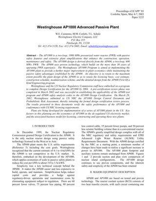
6. Figure 4 – AP1000 RCS and Passive Core Cooling System
Typical Plant AP600 AP1000
- Loss Flow Margin to ~ 1 - 5% ~16% ~19%
DNBR Limit
- Feedline Break oC (oF) >0 (>0) ~94 (~170) ~78 (~140)
Subcooling Margin
- SG Tube Rupture Operator actions Operator actions Operator actions
required in 10 min NOT required NOT required
- Small LOCA 3" LOCA < 8" LOCA < 8" LOCA
core uncovers NO core NO core
PCT ~1500oF uncovery uncovery
- Large LOCA PCT oC (oF) 1093 - 1204 913 1162
with uncertainty (2000 - 2200) (1676) (2124)
Table 2 - AP1000 Safety Margins
6
7. required. For AP1000 the normal water level in the
reactor coolant pipe, the PXS cools the reactor with ample IRWST was raised to provide adequate water inventory
margin to the peak clad temperature limit. without changing the structure.
IV.B. Safety Injection and Depressurization IV.D. Passive Containment Cooling System
The PXS uses three sources of water to maintain core The passive containment cooling system (PCS),
cooling through safety injection. These injection sources provides the safety-related ultimate heat sink for the plant.
include the core makeup tanks (CMTs), the accumulators, The PCS cools the containment following an accident so
and the in-containment refueling water storage tank that design pressure is not exceeded and pressure is rapidly
(IRWST). These injection sources are directly connected reduced. The steel containment vessel provides the heat
to two nozzles on the reactor vessel so that no injection transfer surface that removes heat from inside the
flow can be spilled in case of larger breaks. containment and transfers it to the atmosphere. Heat is
Long-term injection water is provided by gravity from removed from the containment vessel by the continuous,
the IRWST, which is located in the containment just above natural circulation of air. During an accident, air cooling is
the RCS loops. Normally, the IRWST is isolated from the supplemented by water evaporation. The water drains by
RCS by squib valves and check valves. This tank is gravity from a tank located on top of the containment
designed for atmospheric pressure. The RCS must be shield building.
depressurized before injection can occur. The RCS is The containment for AP1000 has the same diameter as
automatically controlled to reduce pressure to about 0.83 that for AP600. The height has been increased to provide
bar (12 psig), at which point the head of water in the additional free volume. This additional free volume, with a
IRWST overcomes the low RCS pressure and the pressure change of material for the vessel shell, provides increased
loss in the injection lines. The PXS provides margin to vessel design pressure from accident pressures
depressurization using the four stages of the automatic over AP600.
depressurization system (ADS) to permit a relatively slow, Analysis shows that during severe accidents the
controlled RCS pressure reduction. AP1000 containment is likely to remain intact and to not be
To maintain similar margins for accidents requiring bypassed. As a result, the plants have a significantly
safety injection, a few lines in the PXS were made larger reduced frequency of release of large amounts of
for AP1000. In addition, the CMTs were enlarged to radioactivity following core damage in an accident. The
provide adequate margin without requiring redesign of PCS cooling capability is very reliable with its 3 way
adjacent piping and structure. redundant (and diverse) water drain valves. In addition,
even with failure of water drain, air-only cooling is capable
IV.C. Passive Residual Heat Removal of maintaining the containment below the predicted failure
pressure. Other contributing factors include improved
The PXS includes one passive residual heat removal containment isolation and reduced potential containment
heat exchanger (PRHR HX). The PRHR HX is connected bypass sequences including steam generator tube ruptures
through inlet ad outlet lines to RCS loop 1. The PRHR HX (SGTR). This enhanced containment performance supports
protects the plant against transients that upset the normal the technical basis for simplification of offsite emergency
steam generator feedwater and steam systems. It satisfies planning.
the safety criteria for loss of feedwater, feedwater line
breaks, and steam line breaks. V. PROBABILISTIC RISK ASSESSMENT
For AP1000, the PRHR HX horizontal tube portions
were made slightly longer and a few tubes were added to PRA has been used interactively as a part of the design
the existing AP600 PRHR HX tube sheet. PRHR piping process since the beginning of the AP600 program in 1985.
was made larger. These modifications resulted in a 100 Seven major PRA quantifications have been performed on
percent capacity system without affecting surrounding the AP600. One major quantification has been performed
piping and layout design. on the AP1000. During each of these quantifications, the
The IRWST provides the heat sink for the PRHR HX. PRA results were reviewed for potential modifications.
The IRWST water absorbs decay heat for more than one Many design and operation changes have been made based
hour before the water begins to boil. Once boiling starts, on these PRA insights, especially during the earlier AP600
steam passes to the containment. The steam condenses on quantifications.
the steel containment vessel and, after collection, drains by As a result, the AP1000 PRA results show very low
gravity back into the IRWST. The PRHR HX and the core melt and large release frequencies, that are
passive containment cooling system provide indefinite significantly below those of operating plants and well
decay heat removal capability with no operator action below the NRC safety goals. The following shows the core
7
8. melt frequency (CMF) and large release frequency (LRF) • Reduced field manpower
per reactor year. The AP1000 frequencies include • Increased factory work (better quality control)
shutdown events and external events. Shutdown events • Reduction in site congestion
have typically not been quantified for operating plants.
Westinghouse has developed an extensive, detailed 3D
Operating NRC AP1000 computer model of the AP600 nuclear reactor plant. This
CMF ~1 E -4 1 E -4 4.2 E -7 / yr model was developed over eight years, using input from a
LRF ~1 E -5 1 E -6 3.7 E -8 / yr number of design participants from a variety of countries.
Westinghouse also led the effort by Morrison-Knudsen
A major safety advantage of passive plants versus (now a part of the Washington Group) to develop a
conventional PWRs is that long-term accident mitigation is construction schedule using Primavera for AP600 over the
maintained without operator action and without reliance on same period as the 3D-model development. MK used its
offsite or onsite AC power sources. The passive safety construction experience and a detailed knowledge of the
systems provide long-term core cooling and decay heat plant to create a detailed schedule for construction of the
removal without the need for operator actions and without entire plant. This schedule was “logic” driven and included
reliance on active safety-related systems. For limiting activities with industry standard durations. It is based upon
design basis accidents, the core coolant inventory in the a 50 hour, 5 day week and resulted in a 36 month duration
containment for recirculation cooling and boration of the from start of basemat concrete pour to the beginning of fuel
core is sufficient to last for at least 30 days, even if load.
inventory is lost at the design basis containment leak rate. More recently, the 3D plant model was linked to the
There is no difference between AP600 and AP1000 in this construction schedule so that the construction of the plant
regard. PRA sensitivity studies illustrate this improvement. could be viewed as a function of time (4D), Reference 4.
The following frequencies show the CMF for at-power These evaluations have demonstrated the benefit of
internal events with and without operator action: reviewing these schedules with construction specialists
using the visualization capabilities of a 4D-plant model.
Operating AP1000 This initial evaluation of the first portion of the AP600
CMF with operator action ~4 E -5 2.4 E -7 / yr construction schedule showed that the 36 month
without operation action ~2 E -3 1.8 E -5 / yr construction schedule could be reduced by at least 4
months. This study also increased the confidence of
Severe accident phenomenon have been address with potential investors concerning the viability of the schedule
AP1000 design features. The highly redundant and diverse and the plant’s ultimate cost.
ADS prevents high pressure core melt sequences which can The latest technique being utilized to improve the
challenge the containment through direct containment construction schedule is the use of immersive virtual
heating and steam explosions. Core concrete interactions environment techniques (Reference 6). This technique
are prevented by invessel retention of core melt debris. provides another step improvement in the quality of the
Hydrogen ignitors and passive autocatylitic recombiners construction visulation capabilities.
prevent hydrogen explosions. The simplifications resulting from the AP600 design is
estimated to be worth 20 to 30% in capital cost as
VI. COST AND CONSTRUCTION SCHEDULE compared to current evolutionary PWRs. A detailed cost
buildup was developed for the AP600 based on its detailed
The AP600/AP1000 plant costs and construction design information and direct quotes in 1900 commodity
schedules benefit directly from the great simplifications catagories for over 25,000 specific items including
provided by the design. In addition, modular construction components, bulk commodity and other materials, labor,
techniques have been adopted. Three types of modules are indirect and owner’s costs (Reference 5). A plant
employed; structural, mechanical, and piping. The availability of 93% was used in the cost calculations; with
approach was design the plant from the beginning to the design simplifications, margins, and lessons learned, the
maximize the use of modules. These modules are rail AP600/AP1000 plants are expected to exceed this
shippable and would be built in factories and then shipped availability since current operating plants are exceeding
to the plant. At the plant these modules would be this value. Staffing will be reduced for the AP600/AP1000
assembled into larger modules in parallel construction plants due the major simplifications incorporated into their
areas and then lifted into the plant as needed. The designs.
AP600/AP1000 plants uses over 270 modules. The use of The calculated operating costs for the AP600 is
modules provides several benefits, including: estimated to be 4.1 to 4.6¢/kWh. The AP1000 with its
small cost increase and large power increase, results in a
• Reduced construction schedule
8
9. cost per kWh of about 3.0 to 3.5¢.kWh for a twin unit Power 2010 is to support industry initiatives to eliminate
plant. barriers to the deployment of a series of advanced nuclear
plants in the U.S. by the year 2010. The initiative
VII. LICENSING encourages investment in projects that can improve the
economic competitiveness of new nuclear power plants.
In June 1992, AP600 safety analysis and probabilistic The DOE is supporting a program that will effectively
risk assessment reports were submitted to the NRC. The shorten the time between plant contract and power
Commission documented its acceptance of the AP600 operation.
safety systems in the Final Design Approval on September The required lead time for an advanced nuclear plant
3, 1998. This milestone provides a high certainty for the such as AP1000 has been estimated to be approximately 5-
licensability of the AP600 in international markets. In 6 years between the plant order and its commercial
December 1999, the NRC issued the Design Certification operation. This includes approximately 3 to 4 years for
for AP600 as Appendix C of 10CFR Part 52. This makes construction, with the remaining 2 years being required for
the AP600 the only licensed passive safety system nuclear the power company to order long lead items, prepare the
power plant in the world. site and perform startup operations. The Early Site Permit
Westinghouse and the US Nuclear Regulatory (ESP) and Combined Operating License (COL) are part of
Commission staff have embarked on a program to complete the U.S. licensing process established under 10 CFR Part
Design Certification for the AP1000 by 2004. A pre- 52 and would be completed prior to the initiation of site
certification review phase was completed in March 2002 activities.
and was successful in establishing the applicability of the Three US Power companies are currently engaged with
AP600 test program and AP600 safety analysis codes to the the US NRC to complete an ESP for three sites that could
AP1000 Design Certification. accommodate an advanced nuclear plant like AP1000. The
On March 28, 2002, Westinghouse submitted to US ESP licensing process is a significant milestone in the
NRC an application for Final Design Approval and Design realization of new nuclear build in the US. It has been
Certification of the AP1000 standard plant. The projected that the US power companies will receive ESPs
application includes the AP1000 Design Control Document by 2005 thereby allowing the completion of COL and
(Standard Safety Analysis Report and Inspections, Tests, initiation of new plant construction activities.
Analysis and Acceptance Criteria (ITAAC) and Demonstration of the COL licensing process is an
Probabilistic Risk Assessment (References 1 and 2). The important next step in the realization of the Nuclear Power
NRC formally docketed the application on June 25, 2002 2010 initiative. The Westinghouse AP1000 is well-
signifying its acceptance as a complete safety case. positioned to be the reference plant in COL applications.
Because of the few design changes from AP600, Westinghouse is now working with power companies,
approximately 80 percent of the AP600 Standard Safety architect engineers, and international partners, to plan the
Analysis Report remains unchanged for AP1000. next steps in the deployment of a series of AP1000
For those areas that do change - for example, the safety standard plants in the US under the Nuclear Power 2010
analysis in Chapter 15 - Westinghouse uses the same initiative.
process as for the AP600 to show that the worst-case
scenarios remain within limits for the AP1000. IX. CONCLUSIONS
Westinghouse does not plan to open any new policy issues
by using a different licensing approach for the AP1000 The AP600 is a simple, licensed, mature design, using
from that used for the AP600. proven components in an innovative and elegant approach
The NRC has reviewed the DCD and PRA documents. to safety. The successful evolutionary step from the AP600
They have issued their requests for additional information to the AP1000, with minimum changes, makes the AP1000
by September 30, 2002. Westinghouse provided responses a nuclear plant with a cost per kWh in the range of
to the NRC requests by December 2, 2002. The NRC is electricity prices today. The changes represent a very
now reviewing our responses. Because of the pre- modest increase in the overall plant capital cost. This
certification review and the discussions with the staff slight increase, when divided by the large increase in power
during their review and request writing, Westinghouse output, gives significantly lower electricity cost in the range
believes that the AP1000 Design Certification will proceed of 3.0 to 3.5¢/kWh. The Westinghouse AP1000 represents
in an efficient manner. a nuclear power plant that is economical in the U.S.
deregulated electrical power industry that is ready for
VIII. AP1000 DEPLOYMENT deployment in the near term.
The US Department of Energy is now implementing
the “Nuclear Power 2010” initiative. The goal of Nuclear
9
10. NOMENCLATURE 2. AP1000 Probabilistic Risk Assessment, Revision 0,
March 2002.
ADS - Automatic Depressurization System
ALWR - United States Advanced Light Water Reactor
CMF - Core melt frequency 3. Advanced Light Water Reactor Utility Requirements
CMT - Core Makeup Tank Document, Volume III, ALWR Passive Plant, Revision
I&C - Instrumentation and control 7, 12/95
IRWST - In-Containment Refueling Water Storage Tank
LRF - Large activity release frequency 4. Winters, J.W., “AP1000 Construction Schedule”, Proc.
LOCA - Loss of coolant accident of ICONE 9, paper 9553, April 2001
PCS - Passive Containment Cooling System
PRHR HX - Passive Residual Heat Removal Heat 5. Winters, J.W. and Corletti, M.M., “AP1000
Exchanger Construction and Operating Costs”, Proc. of ICONE 9,
PRA - Probabilistic Risk Assessment paper 9552, April 2001
SGTR - Steam generator tube rupture accident
6. Whisker, V.E, “Using Immersive Virtual Environments
REFERENCES to Develop and Visualize Construction Schedules for
Advanced Nuclear Power Plants”, Proc. of ICAPP ’03,
1. AP1000 Design Control Document, Revision 2, May paper 3271, May 2003
2002.
10