SlideShare ist ein Scribd-Unternehmen logo
1 von 33
Downloaden Sie, um offline zu lesen
Simple Stress and Strain 
Lecturer; 
Dr. Dawood S. Atrushi
Content 
¢ Stress 
¢ Strain (Deformation) 
¢ Stress-Strain relationship 
¢ Hook’s law 
¢ Poisson’s ration 
¢ Thermal or Temperature stress and 
strain 
Wednesday, 2 Strenght of Materials I - DAT October 22, 14
STRESS 
Chapter Chapter 2 2 Stress Stress and and Strain 
Strain 
External and internal forces in a structural member 
2.0 INTRODUCTION 
In the first Chapter we discuss the equations of statics, and how to determine the ground 
reaction for any structure. The method can also be used to determine the internal loads carried 
by the members or parts of a body. We now need to define how these internal loads are 
distributed and carried by the material and the deformation they create. 
2.1 STRESS (SI&4th p. 22-23, 3rd p. 22-23) 
Consider an element of continuous (no voids) and cohesive (no cracks, breaks and defects) 
material subjected to a number of externally applied loads as shown in Fig. 2.1a). It is 
supposed that the member is in equilibrium. 
2.0 INTRODUCTION 
In the first Chapter we discuss the equations of statics, and how to determine the ground 
reaction for any structure. The method can also be used to determine the internal loads carried 
by the members or parts of a body. We now need to define how these internal loads are 
distributed ¢ Consider and carried by the material an element and the deformation of they continuous 
create. 
2.1 STRESS and (SI&cohesive 4th p. 22-23, 3rd p. 22-material 23) 
subjected to a 
Consider number an element of continuous of externally (no voids) and cohesive (no cracks, breaks material subjected to a number of externally applied applied loads as shown loads. 
and defects) 
in Fig. 2.1a). It is 
supposed that the member is in equilibrium. 
Free Body Diagram 
Free Body Diagram 
'F 
n 
'Fn 
'F 
'Ft 
F4 
F4 
F3 F5 
'Fn 
F3 F5 
Cross section: A 'A 
Cross section: A 'A 
F1 
F2 
t 
t 
F1 
F2 
n 
F1 
F2 
(a) (b) 
(a) (b) 
Fig. 2.1 External and internal forces in a structural member 
'Ft 
F2 
F1 
Fig. 2.1 External and internal forces in a structural member 
Wednesday, 3 Strenght of Materials I - DAT October 22, 14 
If we now cut this body, the applied forces can be thought of as being distributed over the cut 
area A as in Fig. 2.1b). Now if we look at infinitesimal regions 'A, we assume the resultant 
If we now cut this body, the applied forces can be thought of as being distributed over the cut 
area A as in Fig. 2.1b). Now if we look at infinitesimal regions 'A, we assume the resultant
Definition of Stress 
In the previous figures; 
l ΔA infinitesimal regions 
l ΔF distributed/resultant force on ΔA 
l ΔA is extremely small, ΔF is uniform 
l Entire area A is subject to an infinite number of 
forces, each one acts over a small area ΔA. 
Stress is the intensity of the internal 
force on a specific plane passing 
through a point. 
Wednesday, 4 Strenght of Materials I - DAT October 22, 14
look at the whole sectioned area, we can say number of forces, we Stress can define expression 
where each one (of magnitude stress. 
Definition: Stress is the intensity of the ¢ Mathematically, passing stress through can be 
a point. 
Mathematically, expressed as; 
stress can be expressed as 
lim F 
A ' 
A 
' 
V   
' o0 
Dividing the magnitude of internal force 'F by let ¢ If we let ΔA approach zero, we obtain the 
stress at a point. 
'A approach zero, we obtain the stress at body, which depends on the position that important concepts that we introduced in mechanics 5 Strenght of Materials I - DAT Wednesday, October 22, 14 
Normal and Shear Stress
and carried by the material and the deformation they create. 
STRESS (SI&4th p. 22-23, 3rd p. 22-23) 
Normal and Shear Stress 
an element of continuous (no voids) and cohesive (no cracks, breaks and defects) 
subjected to a number of externally applied loads as shown in Fig. 2.1a). It is 
that the member is in equilibrium. 
Normal Stress, σ 
¢ Now let’s resolve the 
force ΔF in normal and 
tangential direction of 
the acting area. The 
intensity of the force or 
force per unit area 
acting normally to 
section A is called 
Normal Stress 
'F 
'Fn 
'Ft 
F4 
Cross section: A 'A 
F1 
Wednesday, 6 Strenght of Materials I - DAT October 22, 14 
F2 
F3 F5 
Free Body Diagram 
F1 
F2 
t 
n 
(a) (b) 
Fig. 2.1 External and internal forces in a structural member 
cut this body, the applied forces can be thought of as being distributed over the cut
we need to consider both magnitude and direction Now let’s resolve the force 'F in normal and tangential 2.1b). The intensity of the force or force per unit Normal Stress, V (sigma), and it is expressed as: 
¢ Normal stress, σ (sigma) is expressed 
as: 
F 
' 
lim n 
A ' 
V 
  ' o0 
A 
If this stress “pulls” on the area it is referred as “pushes” on the area it is called Compressive Stress The intensity or force per unit area acting tangentially it is expressed as: 
¢ If this stress “pulls” on the area it is 
referred as Tensile Stress and defined 
as Positive. 
¢ If it “pushes” on the area it is called 
Compressive Stress Negative. 
' 
F 
and defined as 
lim t 
A ' 
W 
  ' o0 
A 
7 Strenght of Materials I - DAT Wednesday, October 22, 14 
Average Normal Stress (SI&4th p. 24-31, 3rd p. 27-
Now let’s resolve the force 'F in normal and 2.1b). The intensity of the force or force per unit Normal Stress, V (sigma), and it is expressed as: 
F 
' 
lim n 
A ' 
V 
  A 
If this stress “pulls” on the area it is referred “pushes” on the area it is called Compressive Stress The intensity or force per unit area acting tangentially it is expressed as: 
Shear Stress, τ 
' o0 
¢ The intensity or force per unit area 
acting tangentially to A is called Shear 
Stress, τ (tau), and it is expressed 
as: 
F 
' 
lim t 
A ' 
W 
  ' o0 
A 
Average Normal Stress (SI&4th p. 24-31, 3rd p. To begin, we only look at beams that carry tensile and slender. Such beams can then be assumed Wednesday, 8 Strenght of Materials I - DAT October 22, 14
“pushes” on the area it is called Compressive Stress The intensity or force per unit area acting tangentially it is expressed as: 
Average Normal Stress 
F 
' 
lim t 
A ' 
W 
  Average Normal Stress (SI&4th p. 24-31, 3rd p. 27-To begin, we only look at beams that carry tensile and slender. Such beams can then be assumed to simplified to: 
¢ Let us look at beams ' o0 
that A 
carry tensile or 
compressive loads and which are long 
and slender. Such beams can then be 
assumed to carry a constant stress, and 
the Equation can be simplified to: 
V   F A 
We call this either Average Normal Stress or Uniform Units of Stress 
The units in the SI system is the Newton per square In engineering, Pa seems too small, so we usually Kilo Pascal KPa (=Pau103) ¢ We call this either Average Normal 
Stress or Uniform Uniaxial Stress. 
Wednesday, 9 Strenght of Materials I - DAT October 22, 14
mechanical analysis of deformable solids 
force system 
distributed along a 
continuous surface ≡ Mechanics of materials of structures: 
Mechanics of materials of structures: 
1. Stress analysis → whether or not internal forces 
(stresses) due to external STATICS: STRENGTH OF MATERIALS: 
(stresses) due to external loading cause a) Statics b) Strength of materials 
STATICS: STRENGTH OF MATERIALS: 
Force system distributed 
along a continuous surface 
force system 
distributed along a 
continuous surface 
Wednesday, 10 Strenght of Materials I - DAT October 22, 14
• The loaded perpendicular • The the • The resultant of the internal forces for an axially 
loaded member is normal to a section cut 
perpendicular to the member axis. 
• The force intensity on that section is defined as 
the normal stress. 
• A uniform distribution of stress in a section 
infers that the line of action for the resultant the internal forces passes through the centroid 
of the section. 
• • A uniform distribution of stress is only 
possible if the concentrated loads on the end 
sections of two-force members are applied at 
the section centroids. This is referred to as 
centric loading. 
• If a two-force member is eccentrically loaded, 
then the resultant of the The Civil and Planning Faculty stress of Engineering distribution Engineering Education – State University in of • The normal stress 
at a particular 
' 
F 
point may not be 
equal to the 
average stress but 
the resultant of the 
stress distribution 
must satisfy 
V V 
P V aveA dF V dA 
P 
Wednesday, 11 Strenght of Materials I - DAT October 22, 14 
The equal stress • The indeterminate, alone. 
Internal forces for an 
axially loaded member 
• The normal stress at a particular point may not be 
equal to the average stress but the resultant of the 
stress distribution must satisfy 
    ³   ³ 
A 
A 
A 
ave 
A 
  
' 
  
' o 
0 
lim 
• The detailed distribution of stress is statically 
indeterminate, i.e., can not be found from statics 
alone.
Measurement of mechanical (strength) properties 
Uniaxial Compressive 
Test 
Measurement of mechanical (strength) properties 
Uniaxial compressive test of a concrete block: 
http://www.muszakiak.com/diagnosztika-es-anyagvizsgalat/beton-szilardsagi-vizsgalatok.html 
http://metrumkft.hu/termekek/betonszilardsagvizsgalo 
F 
F 
Wednesday, 12 Strenght of Materials I - DAT October 22, 14 
http://www.muszakiak.com/diagnosztika-es-anyagvizsgalat/beton-szilardsagi-vizsgalatok.html 
F 
F
Units of Stress 
¢ The units in the SI system is the 
Newton per square meter or Pascal, 
i.e. : Pa = N/m2. 
¢ In engineering, Pa seems too small, so 
we usually use: 
Wednesday, 13 Strenght of Materials I - DAT October 22, 14 
Stress (ı) 
material is subjected to an external force, a resisting force is set up within the component. 
internal resistance force per unit area acting on a material or intensity of the forces distributed 
given section is called the stress at a point. 
It uses original cross section area of the specimen and also known as engineering stress conventional stress. 
Therefore, P 
A 
T  
P is expressed in Newton (N) and A, original area, in square meters (m2), the stress ǔ will expresses in N/ m2. This unit is called Pascal (Pa). 
As Pascal is a small quantity, in practice, multiples of this unit is used. 
1 kPa = 103 Pa = 103 N/ m2 (kPa = Kilo Pascal) 
1 MPa = 106 Pa = 106 N/ m2 = 1 N/mm2 (MPa = Mega Pascal) 
1 GPa = 109 Pa = 109 N/ m2 (GPa = Giga Pascal) 
take an example: A rod 10 mm q10 mm cross-section is carrying an axial tensile load this rod the tensile stress developed is given by 
3 
10 10 10 P kN q 
N
Example 1 
An 80 kg lamp is 
supported by a 
single electrical 
copper cable of 
diameter d = 3.15 
mm. What is the 
stress carried by 
the cable. 
A d 0.00315 
  u  m 
F 784 
100 6 
     V 
a a 
80kg 
F 
F 
Section 
a-a 
A 
d 
FBD 
Wednesday, 14 Strenght of Materials I - DAT October 22, 14 
Stress 
the SI system is the Newton per square meter or Pascal, i.e. : Pa = N/m2. 
engineering, Pa seems too small, so we usually use: 
Pascal KPa (=Pau103) e.g. 20,000Pa=20kPa 
Mega Pascal MPa (=Pau106) e.g. 20,000,000Pa=20MPa 
Pascal GPa (=Pau109) e.g. 20,000,000,000Pa=20GPa 
2.1: An 80 kg lamp is supported by a single electrical 
of diameter d = 3.15 mm. What is the stress carried 
determine the stress in the wire/cable as Eq. (2.4), we need 
sectional area A of the cable and the applied internal 
6 2 
2 2 
7.793 10 
4 
S S 
4 
u 
    
F   mg   80u9.8   784N 
. MPa 
A . 
7 793 10 
6   
u 
Stress (SI4th p. 48-49, 3rd p. 51-52) 
Example 2.1, we may concern whether or not 80kg would be too heavy, or say 
stress would be too high for the wire/cable, from the safety point of view. Indeed, 
of most important indicators of structural strength. When the stress (intensity of
Kilo Pascal KPa (=Pau103) e.g. 20,000Pa=Mega Pascal MPa (=Pau106) e.g. 20,000,000Pa=Giga Pascal GPa (=Pau109) e.g. 20,000,000,000Pa=Example 2.1: An 80 kg lamp is supported by a single electrical 
copper cable of diameter d = 3.15 mm. What is the stress carried 
by the cable. 
To determine the stress in the wire/cable as Eq. (2.4), we need 
the area A of the cable and the applied internal 
force Pascal MPa (=Pau106) e.g. 20,000,000Pa=Giga Pascal GPa (=Pau109) e.g. 20,000,000,000Pa=Example 2.1: An 80 kg lamp is supported by a single electrical 
copper cable of diameter d = 3.15 mm. What is the stress carried 
by the cable. 
To determine the stress in the wire/cable as Eq. (2.4), we need 
the cross sectional area A of the cable and the applied internal 
force F: 
Allowable Stress (SI4th p. 48-49, 3rd p. 51-52) 
From Example 2.1, we may concern whether or not 80kg 100.6MPa stress would be too high for the wire/cable, from the stress is one of most important indicators of structural strength. Mega In engineering, Pa seems too small, so we usually use: 
Allowable Stress (SI4th p. 48-49, 3rd p. 51-52) 
From Example 2.1, we may concern whether or not 80kg 100.6MPa stress would be too high for the wire/cable, from Kilo Pascal KPa (=Pau103) e.g. 20,000Pa=Solution 
Mega Pascal MPa (=Pau106) e.g. 20,000,000Pa=Example Giga 1 
Pascal GPa (=Pau109) e.g. 20,000,000,000Pa=Example 2.1: An 80 kg lamp is supported by a single electrical 
copper cable The cross of diameter sectional d = 3.15 area mm. A What of the 
is the stress carried 
¢ by the cable. 
To determine cable the and stress the in applied the wire/internal 
cable as Eq. (2.4), we need 
the cross force sectional F: 
area A of the cable and the applied internal 
force F: 
A d   u  m 
6 2 
2 2 
7.793 10 
0.00315 
2 2 
0.00315 
2 2 
A d 0.00315 
4 
  u  m 
S S 
    
S S 
4 
u 
4 
4 
S 
u 
  
u 
    
F   mg   80u9.8   784N 
  7.793 u 10 
 m 
7.793 10 
4 
4 
F   mg   80u9.8   784N 
F 784 
100 6 
F 784 
100 6 
so . MPa 
     V 
6 2 
so . MPa 
     V 
F A 7 . 
793 784 
10 
100 6 
6   
u 
6 2 
so . MPa 
     V 
A . 
6   
7 793 10 
6   
u 
A . 
7 793 u 
10 
Allowable Stress (SI4th p. 48-49, 3rd p. 51-52) 
From 15 Example 2.1, Strenght we may of Materials concern I - DAT whether Wednesday, or October not 22, 80kg 14 
would 100.6MPa would be too high for the wire/cable, from the safety stress is one of most important indicators of structural strength. When
Review of Static 
Example 2 
• 7KHVWUXFWXUHLVGHVLJQHG 
WRVXSSRUWDN1 ORDG 
• 7KHVWUXFWXUHFRQVLVWVRID 
ERRPDQGURGMRLQHGE 
SLQV]HURPRPHQW 
FRQQHFWLRQV
DWWKH 
MXQFWLRQVDQGVXSSRUWV 
• 3HUIRUPDVWDWLFDQDOVLV 
WRGHWHUPLQHWKHLQWHUQDO 
IRUFHLQHDFKVWUXFWXUDO 
PHPEHUDQGWKHUHDFWLRQ 
IRUFHVDWWKHVXSSRUWV 
Wednesday, 16 Strenght of Materials I - DAT October 22, 14 
The Civil and Planning Engineering Education Department 
Faculty of Engineering – State University of Yogyakarta
Deformation 
¢ Whenever a force is applied to a body, 
its shape and size will change. These 
changes are referred as deformations. 
¢ Positive (elongation) or negative 
(contraction) deformation; 
2.2 DEFORMATION (SI4th p. 67-68, 3rd p. 70) 
Whenever a force is applied to a body, its shape and size will change. These changes referred as deformations. These deformations can be thought of being either positive 
(elongation) or negative (contraction) in sign as shown in Fig. 2.2. 
DEFORMATION (SI4th p. 67-68, 3rd p. 70) 
Whenever a force is applied to a body, its shape and size will change. These changes are 
referred as deformations. These deformations can be thought of being either positive 
elongation) or negative (contraction) in sign as shown in Fig. 2.2. 
F F 
F 
F F 
(+) () 
(+) () 
Original length 
Deformation 
(elongation) 
F Deformation 
Deformation 
(contraction) 
(contraction) 
Original length 
Deformation 
(elongation) 
Original length 
Fig. 2.2 Deformation due to applied axial forces 
Original length 
Fig. 2.2 Deformation due to applied axial forces 
Wednesday, 17 Strenght of Materials I - DAT October 22, 14 
It is however very hard to make a relative comparison between bodies or structures of different 
however very hard to make a relative comparison between bodies or structures of different
¢ It is however very hard to make a 
relative comparison between bodies 
or structures of different size and 
length as their individual deformations 
will be different. This requires the 
development of the concept of Strain, 
which relates the body’s deformation 
to its initial length. 
Wednesday, 18 Strenght of Materials I - DAT October 22, 14
F F 
(+) () 
Original length 
Deformation 
(elongation) 
F F 
Deformation 
(contraction) 
Deformation 
(contraction) 
Original length 
Original length 
Strain 
Deformation 
(elongation) 
Normal Strain 
¢ The elongation (+ve) or contraction 
(−ve) of a body per unit length is 
termed Strain. 
Original length 
Fig. 2.2 Deformation due to applied axial forces 
It is however very hard to make a relative comparison between bodies or structures of different 
size and length as their individual deformations will be different. This requires the development 
of the concept of Strain, which relates the body’s deformation to its initial length. 
2.3 STRAIN (SI p.68-69; 4th p. 67-69; 3rd p.71-72) 
Normal Strain 
The elongation (+ve) or contraction (ve) of a body per unit length is termed Strain. 
n 
A 'S B A’ 
A 'S B A’ 
B’ 
F1 
'S’ 
B’ 
'S’ 
F2 
(a) Before deformed (b) After deformed 
F3 
(a) Before deformed (b) After deformed 
Fig. 2.3 Generalized deformation due to applied forces 
Wednesday, 19 Strenght of Materials I - DAT October 22, 14 
F3 
F2 
F1 
n 
Fig. 2.3 Generalized deformation due to applied forces 
Let’s take the arbitrarily shaped body in Fig. 2.3 as an example. Consider the infinitesimal 
line segment AB that is contained within the undeformed body as shown in Fig. 2.3(a). The 
Let’s take the arbitrarily shaped body in Fig. 2.3 as an example. Consider the infinitesimal
(a) Before deformed Fig. 2.3 Generalized deformation due Let’s take the arbitrarily shaped body in Fig. 2.3 as an line segment AB that is contained within the undeformed line AB lies along the n-axis and has an original length ¢ After deformation, the generalized 
and B are strain displaced mathematically to A’ and B’ can and be 
in general the line The change expressed in length as; 
of the line is therefore 'S-'S’. We strain mathematically as 
'  
' 
lim S' S 
B A ' 
H 
  
(BoA along n) o 
S 
Average Normal Strain 
If the stress in the body is everywhere constant, in other the material (e.g. uniform uniaxial tension or compression) be computed 20 by 
Strenght of Materials I - DAT Wednesday, October 22, 14 
L  
L
and B are displaced to A’ and B’ and in general the The change in length of the line is therefore 'S-'S’. strain Average mathematically Normal as 
Strain 
'  
' 
lim S' S 
B A ' 
If the H 
stress   
in the body (Bis oeverywhere 
A along n) ¢ o 
S 
constant, in other words, the 
Average deformation Normal Strain 
is uniform in the material 
If the stress (e.g. in uniform the body uniaxial is everywhere tension or 
constant, in other the material compression), (e.g. uniform the uniaxial strain ε tension can be 
or compression) be computed computed by 
by; 
L 
 
Deformed Original ' 
  L 
i.e. the change in length of the body over its original L L 
H   
L 
Original 
Wednesday, 21 Strenght of Materials I - DAT October 22, 14
Unit of Strain 
¢ The normal strain is a dimensionless quantity 
since it is a ratio of two lengths, but it is common in 
practice to state it in terms of a ratio of length 
units. i.e. meters per meter (m/m) 
¢ Usually, for most engineering applications ε is very 
small, so measurements of strain are in 
micrometers per meter (μm/m) or (μ/m). 
¢ Sometimes for experiment work, strain is 
expressed as a percent, e.g. 0.001m/m = 0.1%. A 
normal strain of 480μm for a one-meter length is 
said: ε= 480×10-6 = 480(μm/m) = 0.0480% = 480μ 
(micros) = 480μs (micro strain) 
Wednesday, 22 Strenght of Materials I - DAT October 22, 14
Example 3 
¢ If it is measured that the a cable was 
elongated by 1.35 mm due to the 
weight of the light, what would its 
strain be? 
Wednesday, 23 Strenght of Materials I - DAT October 22, 14
Stress-Strain Relationship 
Material Test and Stress-Strain Diagram 
¢ The material strength depends on its 
ability to sustain a load without undue 
deformation or failure. 
¢ The property is inherent in the 
material itself and must be determined 
by experiment. 
¢ The tests are performed in universal 
test machine. 
Wednesday, 24 Strenght of Materials I - DAT October 22, 14
2.4 STRESS-STRAIN RELATIONSHIP, HOOKE'S LAW (SI4th p.83-85-95) 
Material Test and Stress-Strain Diagram 
The material strength depends on its ability to sustain a load without undue deformation failure. The property is inherent in the material itself and must be determined by experiment. 
One of the most important tests to perform in this regard is the tension or compression. so, a bunch of standard specimen is made. The test is performed in universal test machine. 
Shown in Fig. 2.4 is the specimen and test result of Stress-Strain Diagram. 
2.4 STRESS-STRAIN RELATIONSHIP, HOOKE'S LAW (SI4th p.83-93; p.85-95) 
Material Test Material and Stress-Strain The material strength depends test Diagram 
on its  
ability to sustain a load without undue deformation failure. The property is inherent in the material itself and must be determined by experiment. 
One of the most Stress-important Strain tests to perform Diagram 
in this regard is the tension or compression. To so, a bunch of standard specimen is made. The test is performed test machine. 
Shown in Fig. 2.4 is the specimen and test result of Stress-Strain F 
Standard 
Specimen Yield stress 
F 
V 
V 
Elastic Yielding Hardening VY 
VY 
Ultimate 
stress Vu 
Fracture 
stress Vf 
Plastic behavior 
Elastic 
behavior 
ProportionalVpl 
limit 
Fig. 2.4 Material test and Stress-Strain Diagram 
Wednesday, 25 Strenght of Materials I - DAT October 22, 14 
H 
Elastic Yielding Hardening Necking 
Standard 
Specimen Yield stress 
Ultimate 
stress Vu 
Fracture 
stress Vf 
Plastic behavior 
Elastic 
behavior 
ProportionalVpl 
limit 
Fig. 2.4 Material test and Stress-Strain Diagram 
F 
F 
H 
The Stress-Strain diagram consists of 4 stages during the whole process, elastic, yielding, 
hardening and necking stages respectively. From yielding stage, some permanent plastic 
deformation occurs. About 90% of engineering problems only concern the elastic deformation 
The Stress-Strain diagram consists of 4 stages during the whole process, elastic, yielding, 
hardening and necking stages respectively. From yielding stage, some permanent
Hooke’s Law 
¢ The stress-strain linear relationship was 
discovered by Robert Hook in 1676 and is 
known as Hooke's law. 
¢ It is mathematically represented by; 
V   EH where E is terms as the Modulus of Elasticity For l E most is Modulus of engineering of Elasticity or metal Young's 
Modulus with units of N/m2 or Pa (material, or 
GPa GPa) . For mild steel it is about 
2.5 200GPa~POISSON'S 210GPa. 
RATIO (SI4th Ed Definition 
Wednesday, 26 Strenght of Materials I - DAT October 22, 14
When the load P is applied to the bar it changes strain in axial direction and in lateral/radial direction axial Poisson’s Ratio 
¢ When a 
deformable body is 
stretched by a 
tensile force, not 
only does it 
elongate but it also 
contract laterally, 
i.e. it would 
contract in other 
two dimensions. 
v Lateral Strain 
H 
Wednesday, 27 Strenght of Materials I - DAT October 22, 14 
G 
L 
H   
In early 1800s, French scientist Poisson realized two strains is a constant. We called the constant Lateral 
Axial Strain 
H 
Axial 
      Original shape 
Defrormed shape 
F 
F 
r Gr 
L 
L+G 
(a) Fig. 2.5 Relationship of the axial The negative sign is used here since longitudinal contraction (negative strain), vice versa. So Poisson’s
direction of force and yet its sides expand laterally as in Fig. 2.5(b). 
When the load P is applied to the bar it changes the bar’s length by G and its radius by Gr 
G 
H   
¢ Likewise, a 
compressive 
force acting on a 
deformable body 
cause it to 
contract in the 
direction of force 
and yet its sides 
expand laterally 
r 
H 
Lateral 
v Lateral Strain 
      (2.11) 
L 
Gr 
Wednesday, 28 Strenght of Materials I - DAT October 22, 14 
. The 
strain in axial direction and in lateral/radial direction are respectively 
axial L 
r 
lateral 
G 
H   
In early 1800s, French scientist Poisson realized that within elastic range the ratio of these 
two strains is a constant. We called the constant as Poisson’s ratio by v (Nu) 
Axial 
Axial Strain 
H 
Original shape 
Defrormed shape 
F 
F 
r Gr 
L 
L+G 
Original shape 
Defrormed 
shape 
F 
F 
L – G 
r 
(a) (b) 
Fig. 2.5 Relationship of the axial strain with the lateral strain 
The negative sign is used here since longitudinal elongation (positive strain) cause lateral 
contraction (negative strain), vice versa. So Poisson’s ration is positive, i.e. vt0.
terms as the Modulus of Elasticity or Young's Modulus with units engineering metal material, GPa is used, e.g. mild steel is about 200GPa~POISSON'S RATIO (SI4th Ed p104-105; 3rd Ed p107-108) 
deformable body ¢ is When stretched the by load a tensile P is applied force, not to only the bar 
does it elongate laterally, i.e. it would it changes contract the in bar’s other length two dimensions by δ and 
as shown compressive force its radius acting by on δr. a The deformable strain in body axial 
cause it to force and yet its sides expand laterally as in Fig. 2.5(b). 
load P is applied to direction the and in lateral/radial direction 
direction and are in lateral/respectively; 
bar it changes the bar’s length by G and its radius radial direction are respectively 
G 
H   
axial L 
G 
r 
r 
H   
lateral 
1800s, French scientist Poisson realized that within elastic range the a constant. We called the constant as Poisson’s ratio by v (Nu) 
Wednesday, 29 Strenght of Materials I - DAT October 22, 14 
H 
Lateral 
Lateral Strain 
H
Likewise, a compressive force acting on a deformable direction of force and yet its sides expand laterally as in When the load P is applied to the bar it changes the bar’s strain in axial direction and in lateral/radial direction are G 
H axial   
¢ Within the elastic range, the ratio of 
these two strains is a constant, L 
and it 
is called Poisson’s ratio by v (Nu); 
v Lateral Strain 
H 
¢ Poisson’s ration is positive, i.e. v≥0. 
Wednesday, 30 Strenght of Materials I - DAT October 22, 14 
H lateral 
In early 1800s, French scientist Poisson realized that two strains is a constant. We called the constant as Poisson’s Lateral 
Axial Strain 
H 
Axial 
      Original shape 
Defrormed shape 
F 
F
Remarks 
¢ The lateral strain is caused only by 
axial force. No force or stress acts in 
lateral direction; 
¢ Lateral strain is the same in all lateral 
direction; 
¢ Usually 0 ≤ v ≤ 0.5 . For most linearly 
elastic material v=0.3; 
¢ Poisson’s ratio is a constant. Wednesday, 31 Strenght of Materials I - DAT October 22, 14
Strain in Lateral Direction 
¢ For bars subjected to a tensile stress 
σx, the strains in the y and z planes 
are: 
­ 
H 
°°° 
V 
H H 
® 
°°° 
H H 
¯ 
  
x 
E 
v v 
      
x 
y x 
V 
v v 
      
E 
V 
E 
x 
x 
z x 
2.6 THERMAL STRAIN (SI4th Ed p. 148-152; 3rd 32 Strenght of Materials I - DAT Wednesday, October 22, 14 
Thermal Deformation 
When the temperature of a body is changed, its overall

Weitere ähnliche Inhalte

Was ist angesagt?

Stress and strain- mechanics of solid
Stress and strain- mechanics of solidStress and strain- mechanics of solid
Stress and strain- mechanics of solidKaushal Patel
 
Strength of materials by A.Vinoth Jebaraj
Strength of materials by A.Vinoth JebarajStrength of materials by A.Vinoth Jebaraj
Strength of materials by A.Vinoth JebarajVinoth Jebaraj A
 
Lecture 2 principal stress and strain
Lecture 2 principal stress and strainLecture 2 principal stress and strain
Lecture 2 principal stress and strainDeepak Agarwal
 
Simple stresses and strain
Simple stresses and strainSimple stresses and strain
Simple stresses and strainTejashri Gulve
 
Mechanics Of Solids- Stress Transformation in 3D
Mechanics Of Solids- Stress Transformation in 3DMechanics Of Solids- Stress Transformation in 3D
Mechanics Of Solids- Stress Transformation in 3DShaheryar Ahmad
 
1 static failure theories ductile r1
1 static failure theories ductile r11 static failure theories ductile r1
1 static failure theories ductile r1Himanshu Keshri
 
Theories of Failures (STATIC LOADING)
Theories of Failures  (STATIC LOADING)Theories of Failures  (STATIC LOADING)
Theories of Failures (STATIC LOADING)Jawed Shaikh
 
Lec 2 stress strain diagram (lec 2)
Lec 2 stress strain diagram (lec 2)Lec 2 stress strain diagram (lec 2)
Lec 2 stress strain diagram (lec 2)Abdul Rehman Memon
 
6 Machine design theories of failure
6 Machine design theories of failure6 Machine design theories of failure
6 Machine design theories of failureDr.R. SELVAM
 
Theories of failure
Theories of failureTheories of failure
Theories of failureOnkarpowar3
 
Mechanics of materials
Mechanics of materialsMechanics of materials
Mechanics of materialsSelf-employed
 
A study on _ buckling
A study on _ bucklingA study on _ buckling
A study on _ bucklingKishan Sharma
 

Was ist angesagt? (20)

Stress and strain- mechanics of solid
Stress and strain- mechanics of solidStress and strain- mechanics of solid
Stress and strain- mechanics of solid
 
Strength of materials by A.Vinoth Jebaraj
Strength of materials by A.Vinoth JebarajStrength of materials by A.Vinoth Jebaraj
Strength of materials by A.Vinoth Jebaraj
 
Strength of materials
Strength of materialsStrength of materials
Strength of materials
 
Lecture 2 principal stress and strain
Lecture 2 principal stress and strainLecture 2 principal stress and strain
Lecture 2 principal stress and strain
 
Simple stresses and strain
Simple stresses and strainSimple stresses and strain
Simple stresses and strain
 
Stress concentration
Stress concentrationStress concentration
Stress concentration
 
Mechanics Of Solids- Stress Transformation in 3D
Mechanics Of Solids- Stress Transformation in 3DMechanics Of Solids- Stress Transformation in 3D
Mechanics Of Solids- Stress Transformation in 3D
 
Stress and strain
Stress and strainStress and strain
Stress and strain
 
1 static failure theories ductile r1
1 static failure theories ductile r11 static failure theories ductile r1
1 static failure theories ductile r1
 
Basics of strength of materials
Basics of strength of materialsBasics of strength of materials
Basics of strength of materials
 
Theories of Failures (STATIC LOADING)
Theories of Failures  (STATIC LOADING)Theories of Failures  (STATIC LOADING)
Theories of Failures (STATIC LOADING)
 
Torsion
TorsionTorsion
Torsion
 
Strain energy
Strain energyStrain energy
Strain energy
 
Lec 2 stress strain diagram (lec 2)
Lec 2 stress strain diagram (lec 2)Lec 2 stress strain diagram (lec 2)
Lec 2 stress strain diagram (lec 2)
 
6 Machine design theories of failure
6 Machine design theories of failure6 Machine design theories of failure
6 Machine design theories of failure
 
Fatigue Failure Slides
Fatigue Failure SlidesFatigue Failure Slides
Fatigue Failure Slides
 
Theories of failure
Theories of failureTheories of failure
Theories of failure
 
Mechanics of materials
Mechanics of materialsMechanics of materials
Mechanics of materials
 
A study on _ buckling
A study on _ bucklingA study on _ buckling
A study on _ buckling
 
Normal stress and strain
Normal stress and strainNormal stress and strain
Normal stress and strain
 

Ähnlich wie Simple Stress and Strain

MECHANICS OF MATERIALS Chapter 01.pdf SLIDES
MECHANICS OF MATERIALS  Chapter 01.pdf SLIDESMECHANICS OF MATERIALS  Chapter 01.pdf SLIDES
MECHANICS OF MATERIALS Chapter 01.pdf SLIDESSamraKhalid20
 
Chapter-1 Concept of Stress and Strain.pdf
Chapter-1 Concept of Stress and Strain.pdfChapter-1 Concept of Stress and Strain.pdf
Chapter-1 Concept of Stress and Strain.pdfBereketAdugna
 
Basic mechanical engineering (BMET-101/102) unit 5 part-1 simple stress and ...
Basic mechanical engineering (BMET-101/102) unit 5  part-1 simple stress and ...Basic mechanical engineering (BMET-101/102) unit 5  part-1 simple stress and ...
Basic mechanical engineering (BMET-101/102) unit 5 part-1 simple stress and ...Varun Pratap Singh
 
Unit I Stresses and strain PSG.pptx
Unit I Stresses and strain PSG.pptxUnit I Stresses and strain PSG.pptx
Unit I Stresses and strain PSG.pptxPriya Gajjal
 
Lec 1 som-1 introduction (14 me) lec 1
Lec 1 som-1 introduction (14 me) lec 1Lec 1 som-1 introduction (14 me) lec 1
Lec 1 som-1 introduction (14 me) lec 1Abdul Rehman Memon
 
A presentation on "Axial Stress" by Mushfiqul Arefin Khan Nafi
 A presentation on "Axial Stress" by Mushfiqul Arefin Khan Nafi A presentation on "Axial Stress" by Mushfiqul Arefin Khan Nafi
A presentation on "Axial Stress" by Mushfiqul Arefin Khan NafiMushfiqul Khan Nafi
 
Chapter1 ME slid show (2).pptx
Chapter1 ME slid show (2).pptxChapter1 ME slid show (2).pptx
Chapter1 ME slid show (2).pptxIsIskandar7
 
materials properties
materials propertiesmaterials properties
materials propertiesBilal Khan
 
Stress & Strain PPT.ppt
Stress & Strain PPT.pptStress & Strain PPT.ppt
Stress & Strain PPT.pptBodhiSeal1
 
Stress & Strain PPT.ppt
Stress & Strain PPT.pptStress & Strain PPT.ppt
Stress & Strain PPT.pptBodhiSeal1
 
Introduction to engineering basics
Introduction to engineering basicsIntroduction to engineering basics
Introduction to engineering basicsNirmith Mishra
 
Introduction to engineering basics
Introduction to engineering basicsIntroduction to engineering basics
Introduction to engineering basicsNirmith Mishra
 
Presentation on free body diagram 10.01.03.119
Presentation on free body diagram 10.01.03.119Presentation on free body diagram 10.01.03.119
Presentation on free body diagram 10.01.03.119Safa Rahman
 
Normal stress & Shear Stress
 Normal stress & Shear Stress Normal stress & Shear Stress
Normal stress & Shear StressMESHAL ALMUTAIRI
 
Aerostructure analysis WIKI project
Aerostructure analysis WIKI projectAerostructure analysis WIKI project
Aerostructure analysis WIKI projectMohammad Tawfik
 

Ähnlich wie Simple Stress and Strain (20)

MECHANICS OF MATERIALS Chapter 01.pdf SLIDES
MECHANICS OF MATERIALS  Chapter 01.pdf SLIDESMECHANICS OF MATERIALS  Chapter 01.pdf SLIDES
MECHANICS OF MATERIALS Chapter 01.pdf SLIDES
 
Chapter-1 Concept of Stress and Strain.pdf
Chapter-1 Concept of Stress and Strain.pdfChapter-1 Concept of Stress and Strain.pdf
Chapter-1 Concept of Stress and Strain.pdf
 
Unit 1- simple stress and strain
Unit 1- simple stress and strainUnit 1- simple stress and strain
Unit 1- simple stress and strain
 
Basic mechanical engineering (BMET-101/102) unit 5 part-1 simple stress and ...
Basic mechanical engineering (BMET-101/102) unit 5  part-1 simple stress and ...Basic mechanical engineering (BMET-101/102) unit 5  part-1 simple stress and ...
Basic mechanical engineering (BMET-101/102) unit 5 part-1 simple stress and ...
 
Unit I Stresses and strain PSG.pptx
Unit I Stresses and strain PSG.pptxUnit I Stresses and strain PSG.pptx
Unit I Stresses and strain PSG.pptx
 
Lec 1 som-1 introduction (14 me) lec 1
Lec 1 som-1 introduction (14 me) lec 1Lec 1 som-1 introduction (14 me) lec 1
Lec 1 som-1 introduction (14 me) lec 1
 
Simple Stress and strain
Simple  Stress and strainSimple  Stress and strain
Simple Stress and strain
 
Chap1
Chap1Chap1
Chap1
 
A presentation on "Axial Stress" by Mushfiqul Arefin Khan Nafi
 A presentation on "Axial Stress" by Mushfiqul Arefin Khan Nafi A presentation on "Axial Stress" by Mushfiqul Arefin Khan Nafi
A presentation on "Axial Stress" by Mushfiqul Arefin Khan Nafi
 
Chapter1 ME slid show (2).pptx
Chapter1 ME slid show (2).pptxChapter1 ME slid show (2).pptx
Chapter1 ME slid show (2).pptx
 
materials properties
materials propertiesmaterials properties
materials properties
 
LECTURE 1 W1 Intro Stress_SHH.ppt
LECTURE 1 W1 Intro Stress_SHH.pptLECTURE 1 W1 Intro Stress_SHH.ppt
LECTURE 1 W1 Intro Stress_SHH.ppt
 
Stress & Strain PPT.ppt
Stress & Strain PPT.pptStress & Strain PPT.ppt
Stress & Strain PPT.ppt
 
Stress & Strain PPT.ppt
Stress & Strain PPT.pptStress & Strain PPT.ppt
Stress & Strain PPT.ppt
 
Introduction to engineering basics
Introduction to engineering basicsIntroduction to engineering basics
Introduction to engineering basics
 
Introduction to engineering basics
Introduction to engineering basicsIntroduction to engineering basics
Introduction to engineering basics
 
Presentation on free body diagram 10.01.03.119
Presentation on free body diagram 10.01.03.119Presentation on free body diagram 10.01.03.119
Presentation on free body diagram 10.01.03.119
 
Normal stress & Shear Stress
 Normal stress & Shear Stress Normal stress & Shear Stress
Normal stress & Shear Stress
 
Mm210(2)
Mm210(2)Mm210(2)
Mm210(2)
 
Aerostructure analysis WIKI project
Aerostructure analysis WIKI projectAerostructure analysis WIKI project
Aerostructure analysis WIKI project
 

Mehr von Msheer Bargaray

Lesson 06, shearing stresses (Updated)
Lesson 06, shearing stresses (Updated)Lesson 06, shearing stresses (Updated)
Lesson 06, shearing stresses (Updated)Msheer Bargaray
 
Lesson 06, shearing stresses
Lesson 06, shearing stressesLesson 06, shearing stresses
Lesson 06, shearing stressesMsheer Bargaray
 
Lesson 05, bending and shearing stresses
Lesson 05, bending  and shearing stressesLesson 05, bending  and shearing stresses
Lesson 05, bending and shearing stressesMsheer Bargaray
 
Lesson 05,bending and shearing stresses
Lesson 05,bending and shearing stressesLesson 05,bending and shearing stresses
Lesson 05,bending and shearing stressesMsheer Bargaray
 
Lesson 04, shearing force and bending moment 01
Lesson 04, shearing force and bending moment 01Lesson 04, shearing force and bending moment 01
Lesson 04, shearing force and bending moment 01Msheer Bargaray
 
Lesson 03, simple stress and strain
Lesson 03, simple stress and strainLesson 03, simple stress and strain
Lesson 03, simple stress and strainMsheer Bargaray
 
Introduction to Strength of Materials
Introduction to Strength of MaterialsIntroduction to Strength of Materials
Introduction to Strength of MaterialsMsheer Bargaray
 

Mehr von Msheer Bargaray (11)

Mohr circle
Mohr circleMohr circle
Mohr circle
 
Lesson 07, torsion
Lesson 07, torsionLesson 07, torsion
Lesson 07, torsion
 
Lesson 06, shearing stresses (Updated)
Lesson 06, shearing stresses (Updated)Lesson 06, shearing stresses (Updated)
Lesson 06, shearing stresses (Updated)
 
Lesson 06, shearing stresses
Lesson 06, shearing stressesLesson 06, shearing stresses
Lesson 06, shearing stresses
 
Bending stress in beams
Bending stress in beamsBending stress in beams
Bending stress in beams
 
Lesson 05, bending and shearing stresses
Lesson 05, bending  and shearing stressesLesson 05, bending  and shearing stresses
Lesson 05, bending and shearing stresses
 
Lesson 05,bending and shearing stresses
Lesson 05,bending and shearing stressesLesson 05,bending and shearing stresses
Lesson 05,bending and shearing stresses
 
Lesson 04, shearing force and bending moment 01
Lesson 04, shearing force and bending moment 01Lesson 04, shearing force and bending moment 01
Lesson 04, shearing force and bending moment 01
 
Tutorial 2
Tutorial 2Tutorial 2
Tutorial 2
 
Lesson 03, simple stress and strain
Lesson 03, simple stress and strainLesson 03, simple stress and strain
Lesson 03, simple stress and strain
 
Introduction to Strength of Materials
Introduction to Strength of MaterialsIntroduction to Strength of Materials
Introduction to Strength of Materials
 

Kürzlich hochgeladen

MANUFACTURING PROCESS-II UNIT-2 LATHE MACHINE
MANUFACTURING PROCESS-II UNIT-2 LATHE MACHINEMANUFACTURING PROCESS-II UNIT-2 LATHE MACHINE
MANUFACTURING PROCESS-II UNIT-2 LATHE MACHINESIVASHANKAR N
 
Microscopic Analysis of Ceramic Materials.pptx
Microscopic Analysis of Ceramic Materials.pptxMicroscopic Analysis of Ceramic Materials.pptx
Microscopic Analysis of Ceramic Materials.pptxpurnimasatapathy1234
 
Software Development Life Cycle By Team Orange (Dept. of Pharmacy)
Software Development Life Cycle By  Team Orange (Dept. of Pharmacy)Software Development Life Cycle By  Team Orange (Dept. of Pharmacy)
Software Development Life Cycle By Team Orange (Dept. of Pharmacy)Suman Mia
 
Call Girls Service Nashik Vaishnavi 7001305949 Independent Escort Service Nashik
Call Girls Service Nashik Vaishnavi 7001305949 Independent Escort Service NashikCall Girls Service Nashik Vaishnavi 7001305949 Independent Escort Service Nashik
Call Girls Service Nashik Vaishnavi 7001305949 Independent Escort Service NashikCall Girls in Nagpur High Profile
 
Call Girls Service Nagpur Tanvi Call 7001035870 Meet With Nagpur Escorts
Call Girls Service Nagpur Tanvi Call 7001035870 Meet With Nagpur EscortsCall Girls Service Nagpur Tanvi Call 7001035870 Meet With Nagpur Escorts
Call Girls Service Nagpur Tanvi Call 7001035870 Meet With Nagpur EscortsCall Girls in Nagpur High Profile
 
CCS335 _ Neural Networks and Deep Learning Laboratory_Lab Complete Record
CCS335 _ Neural Networks and Deep Learning Laboratory_Lab Complete RecordCCS335 _ Neural Networks and Deep Learning Laboratory_Lab Complete Record
CCS335 _ Neural Networks and Deep Learning Laboratory_Lab Complete RecordAsst.prof M.Gokilavani
 
247267395-1-Symmetric-and-distributed-shared-memory-architectures-ppt (1).ppt
247267395-1-Symmetric-and-distributed-shared-memory-architectures-ppt (1).ppt247267395-1-Symmetric-and-distributed-shared-memory-architectures-ppt (1).ppt
247267395-1-Symmetric-and-distributed-shared-memory-architectures-ppt (1).pptssuser5c9d4b1
 
Porous Ceramics seminar and technical writing
Porous Ceramics seminar and technical writingPorous Ceramics seminar and technical writing
Porous Ceramics seminar and technical writingrakeshbaidya232001
 
Sheet Pile Wall Design and Construction: A Practical Guide for Civil Engineer...
Sheet Pile Wall Design and Construction: A Practical Guide for Civil Engineer...Sheet Pile Wall Design and Construction: A Practical Guide for Civil Engineer...
Sheet Pile Wall Design and Construction: A Practical Guide for Civil Engineer...Dr.Costas Sachpazis
 
Call for Papers - African Journal of Biological Sciences, E-ISSN: 2663-2187, ...
Call for Papers - African Journal of Biological Sciences, E-ISSN: 2663-2187, ...Call for Papers - African Journal of Biological Sciences, E-ISSN: 2663-2187, ...
Call for Papers - African Journal of Biological Sciences, E-ISSN: 2663-2187, ...Christo Ananth
 
VIP Call Girls Service Hitech City Hyderabad Call +91-8250192130
VIP Call Girls Service Hitech City Hyderabad Call +91-8250192130VIP Call Girls Service Hitech City Hyderabad Call +91-8250192130
VIP Call Girls Service Hitech City Hyderabad Call +91-8250192130Suhani Kapoor
 
Call Girls in Nagpur Suman Call 7001035870 Meet With Nagpur Escorts
Call Girls in Nagpur Suman Call 7001035870 Meet With Nagpur EscortsCall Girls in Nagpur Suman Call 7001035870 Meet With Nagpur Escorts
Call Girls in Nagpur Suman Call 7001035870 Meet With Nagpur EscortsCall Girls in Nagpur High Profile
 
OSVC_Meta-Data based Simulation Automation to overcome Verification Challenge...
OSVC_Meta-Data based Simulation Automation to overcome Verification Challenge...OSVC_Meta-Data based Simulation Automation to overcome Verification Challenge...
OSVC_Meta-Data based Simulation Automation to overcome Verification Challenge...Soham Mondal
 
High Profile Call Girls Nagpur Isha Call 7001035870 Meet With Nagpur Escorts
High Profile Call Girls Nagpur Isha Call 7001035870 Meet With Nagpur EscortsHigh Profile Call Girls Nagpur Isha Call 7001035870 Meet With Nagpur Escorts
High Profile Call Girls Nagpur Isha Call 7001035870 Meet With Nagpur Escortsranjana rawat
 
College Call Girls Nashik Nehal 7001305949 Independent Escort Service Nashik
College Call Girls Nashik Nehal 7001305949 Independent Escort Service NashikCollege Call Girls Nashik Nehal 7001305949 Independent Escort Service Nashik
College Call Girls Nashik Nehal 7001305949 Independent Escort Service NashikCall Girls in Nagpur High Profile
 
MANUFACTURING PROCESS-II UNIT-5 NC MACHINE TOOLS
MANUFACTURING PROCESS-II UNIT-5 NC MACHINE TOOLSMANUFACTURING PROCESS-II UNIT-5 NC MACHINE TOOLS
MANUFACTURING PROCESS-II UNIT-5 NC MACHINE TOOLSSIVASHANKAR N
 
Extrusion Processes and Their Limitations
Extrusion Processes and Their LimitationsExtrusion Processes and Their Limitations
Extrusion Processes and Their Limitations120cr0395
 
VIP Call Girls Service Kondapur Hyderabad Call +91-8250192130
VIP Call Girls Service Kondapur Hyderabad Call +91-8250192130VIP Call Girls Service Kondapur Hyderabad Call +91-8250192130
VIP Call Girls Service Kondapur Hyderabad Call +91-8250192130Suhani Kapoor
 

Kürzlich hochgeladen (20)

MANUFACTURING PROCESS-II UNIT-2 LATHE MACHINE
MANUFACTURING PROCESS-II UNIT-2 LATHE MACHINEMANUFACTURING PROCESS-II UNIT-2 LATHE MACHINE
MANUFACTURING PROCESS-II UNIT-2 LATHE MACHINE
 
Microscopic Analysis of Ceramic Materials.pptx
Microscopic Analysis of Ceramic Materials.pptxMicroscopic Analysis of Ceramic Materials.pptx
Microscopic Analysis of Ceramic Materials.pptx
 
Software Development Life Cycle By Team Orange (Dept. of Pharmacy)
Software Development Life Cycle By  Team Orange (Dept. of Pharmacy)Software Development Life Cycle By  Team Orange (Dept. of Pharmacy)
Software Development Life Cycle By Team Orange (Dept. of Pharmacy)
 
Roadmap to Membership of RICS - Pathways and Routes
Roadmap to Membership of RICS - Pathways and RoutesRoadmap to Membership of RICS - Pathways and Routes
Roadmap to Membership of RICS - Pathways and Routes
 
Call Girls Service Nashik Vaishnavi 7001305949 Independent Escort Service Nashik
Call Girls Service Nashik Vaishnavi 7001305949 Independent Escort Service NashikCall Girls Service Nashik Vaishnavi 7001305949 Independent Escort Service Nashik
Call Girls Service Nashik Vaishnavi 7001305949 Independent Escort Service Nashik
 
Call Girls Service Nagpur Tanvi Call 7001035870 Meet With Nagpur Escorts
Call Girls Service Nagpur Tanvi Call 7001035870 Meet With Nagpur EscortsCall Girls Service Nagpur Tanvi Call 7001035870 Meet With Nagpur Escorts
Call Girls Service Nagpur Tanvi Call 7001035870 Meet With Nagpur Escorts
 
CCS335 _ Neural Networks and Deep Learning Laboratory_Lab Complete Record
CCS335 _ Neural Networks and Deep Learning Laboratory_Lab Complete RecordCCS335 _ Neural Networks and Deep Learning Laboratory_Lab Complete Record
CCS335 _ Neural Networks and Deep Learning Laboratory_Lab Complete Record
 
247267395-1-Symmetric-and-distributed-shared-memory-architectures-ppt (1).ppt
247267395-1-Symmetric-and-distributed-shared-memory-architectures-ppt (1).ppt247267395-1-Symmetric-and-distributed-shared-memory-architectures-ppt (1).ppt
247267395-1-Symmetric-and-distributed-shared-memory-architectures-ppt (1).ppt
 
Porous Ceramics seminar and technical writing
Porous Ceramics seminar and technical writingPorous Ceramics seminar and technical writing
Porous Ceramics seminar and technical writing
 
Sheet Pile Wall Design and Construction: A Practical Guide for Civil Engineer...
Sheet Pile Wall Design and Construction: A Practical Guide for Civil Engineer...Sheet Pile Wall Design and Construction: A Practical Guide for Civil Engineer...
Sheet Pile Wall Design and Construction: A Practical Guide for Civil Engineer...
 
Call for Papers - African Journal of Biological Sciences, E-ISSN: 2663-2187, ...
Call for Papers - African Journal of Biological Sciences, E-ISSN: 2663-2187, ...Call for Papers - African Journal of Biological Sciences, E-ISSN: 2663-2187, ...
Call for Papers - African Journal of Biological Sciences, E-ISSN: 2663-2187, ...
 
VIP Call Girls Service Hitech City Hyderabad Call +91-8250192130
VIP Call Girls Service Hitech City Hyderabad Call +91-8250192130VIP Call Girls Service Hitech City Hyderabad Call +91-8250192130
VIP Call Girls Service Hitech City Hyderabad Call +91-8250192130
 
Call Girls in Nagpur Suman Call 7001035870 Meet With Nagpur Escorts
Call Girls in Nagpur Suman Call 7001035870 Meet With Nagpur EscortsCall Girls in Nagpur Suman Call 7001035870 Meet With Nagpur Escorts
Call Girls in Nagpur Suman Call 7001035870 Meet With Nagpur Escorts
 
OSVC_Meta-Data based Simulation Automation to overcome Verification Challenge...
OSVC_Meta-Data based Simulation Automation to overcome Verification Challenge...OSVC_Meta-Data based Simulation Automation to overcome Verification Challenge...
OSVC_Meta-Data based Simulation Automation to overcome Verification Challenge...
 
High Profile Call Girls Nagpur Isha Call 7001035870 Meet With Nagpur Escorts
High Profile Call Girls Nagpur Isha Call 7001035870 Meet With Nagpur EscortsHigh Profile Call Girls Nagpur Isha Call 7001035870 Meet With Nagpur Escorts
High Profile Call Girls Nagpur Isha Call 7001035870 Meet With Nagpur Escorts
 
College Call Girls Nashik Nehal 7001305949 Independent Escort Service Nashik
College Call Girls Nashik Nehal 7001305949 Independent Escort Service NashikCollege Call Girls Nashik Nehal 7001305949 Independent Escort Service Nashik
College Call Girls Nashik Nehal 7001305949 Independent Escort Service Nashik
 
MANUFACTURING PROCESS-II UNIT-5 NC MACHINE TOOLS
MANUFACTURING PROCESS-II UNIT-5 NC MACHINE TOOLSMANUFACTURING PROCESS-II UNIT-5 NC MACHINE TOOLS
MANUFACTURING PROCESS-II UNIT-5 NC MACHINE TOOLS
 
Extrusion Processes and Their Limitations
Extrusion Processes and Their LimitationsExtrusion Processes and Their Limitations
Extrusion Processes and Their Limitations
 
VIP Call Girls Service Kondapur Hyderabad Call +91-8250192130
VIP Call Girls Service Kondapur Hyderabad Call +91-8250192130VIP Call Girls Service Kondapur Hyderabad Call +91-8250192130
VIP Call Girls Service Kondapur Hyderabad Call +91-8250192130
 
DJARUM4D - SLOT GACOR ONLINE | SLOT DEMO ONLINE
DJARUM4D - SLOT GACOR ONLINE | SLOT DEMO ONLINEDJARUM4D - SLOT GACOR ONLINE | SLOT DEMO ONLINE
DJARUM4D - SLOT GACOR ONLINE | SLOT DEMO ONLINE
 

Simple Stress and Strain

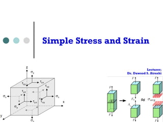
  • 1. Simple Stress and Strain Lecturer; Dr. Dawood S. Atrushi
  • 2. Content ¢ Stress ¢ Strain (Deformation) ¢ Stress-Strain relationship ¢ Hook’s law ¢ Poisson’s ration ¢ Thermal or Temperature stress and strain Wednesday, 2 Strenght of Materials I - DAT October 22, 14
  • 3. STRESS Chapter Chapter 2 2 Stress Stress and and Strain Strain External and internal forces in a structural member 2.0 INTRODUCTION In the first Chapter we discuss the equations of statics, and how to determine the ground reaction for any structure. The method can also be used to determine the internal loads carried by the members or parts of a body. We now need to define how these internal loads are distributed and carried by the material and the deformation they create. 2.1 STRESS (SI&4th p. 22-23, 3rd p. 22-23) Consider an element of continuous (no voids) and cohesive (no cracks, breaks and defects) material subjected to a number of externally applied loads as shown in Fig. 2.1a). It is supposed that the member is in equilibrium. 2.0 INTRODUCTION In the first Chapter we discuss the equations of statics, and how to determine the ground reaction for any structure. The method can also be used to determine the internal loads carried by the members or parts of a body. We now need to define how these internal loads are distributed ¢ Consider and carried by the material an element and the deformation of they continuous create. 2.1 STRESS and (SI&cohesive 4th p. 22-23, 3rd p. 22-material 23) subjected to a Consider number an element of continuous of externally (no voids) and cohesive (no cracks, breaks material subjected to a number of externally applied applied loads as shown loads. and defects) in Fig. 2.1a). It is supposed that the member is in equilibrium. Free Body Diagram Free Body Diagram 'F n 'Fn 'F 'Ft F4 F4 F3 F5 'Fn F3 F5 Cross section: A 'A Cross section: A 'A F1 F2 t t F1 F2 n F1 F2 (a) (b) (a) (b) Fig. 2.1 External and internal forces in a structural member 'Ft F2 F1 Fig. 2.1 External and internal forces in a structural member Wednesday, 3 Strenght of Materials I - DAT October 22, 14 If we now cut this body, the applied forces can be thought of as being distributed over the cut area A as in Fig. 2.1b). Now if we look at infinitesimal regions 'A, we assume the resultant If we now cut this body, the applied forces can be thought of as being distributed over the cut area A as in Fig. 2.1b). Now if we look at infinitesimal regions 'A, we assume the resultant
  • 4. Definition of Stress In the previous figures; l ΔA infinitesimal regions l ΔF distributed/resultant force on ΔA l ΔA is extremely small, ΔF is uniform l Entire area A is subject to an infinite number of forces, each one acts over a small area ΔA. Stress is the intensity of the internal force on a specific plane passing through a point. Wednesday, 4 Strenght of Materials I - DAT October 22, 14
  • 5. look at the whole sectioned area, we can say number of forces, we Stress can define expression where each one (of magnitude stress. Definition: Stress is the intensity of the ¢ Mathematically, passing stress through can be a point. Mathematically, expressed as; stress can be expressed as lim F A ' A ' V ' o0 Dividing the magnitude of internal force 'F by let ¢ If we let ΔA approach zero, we obtain the stress at a point. 'A approach zero, we obtain the stress at body, which depends on the position that important concepts that we introduced in mechanics 5 Strenght of Materials I - DAT Wednesday, October 22, 14 Normal and Shear Stress
  • 6. and carried by the material and the deformation they create. STRESS (SI&4th p. 22-23, 3rd p. 22-23) Normal and Shear Stress an element of continuous (no voids) and cohesive (no cracks, breaks and defects) subjected to a number of externally applied loads as shown in Fig. 2.1a). It is that the member is in equilibrium. Normal Stress, σ ¢ Now let’s resolve the force ΔF in normal and tangential direction of the acting area. The intensity of the force or force per unit area acting normally to section A is called Normal Stress 'F 'Fn 'Ft F4 Cross section: A 'A F1 Wednesday, 6 Strenght of Materials I - DAT October 22, 14 F2 F3 F5 Free Body Diagram F1 F2 t n (a) (b) Fig. 2.1 External and internal forces in a structural member cut this body, the applied forces can be thought of as being distributed over the cut
  • 7. we need to consider both magnitude and direction Now let’s resolve the force 'F in normal and tangential 2.1b). The intensity of the force or force per unit Normal Stress, V (sigma), and it is expressed as: ¢ Normal stress, σ (sigma) is expressed as: F ' lim n A ' V ' o0 A If this stress “pulls” on the area it is referred as “pushes” on the area it is called Compressive Stress The intensity or force per unit area acting tangentially it is expressed as: ¢ If this stress “pulls” on the area it is referred as Tensile Stress and defined as Positive. ¢ If it “pushes” on the area it is called Compressive Stress Negative. ' F and defined as lim t A ' W ' o0 A 7 Strenght of Materials I - DAT Wednesday, October 22, 14 Average Normal Stress (SI&4th p. 24-31, 3rd p. 27-
  • 8. Now let’s resolve the force 'F in normal and 2.1b). The intensity of the force or force per unit Normal Stress, V (sigma), and it is expressed as: F ' lim n A ' V A If this stress “pulls” on the area it is referred “pushes” on the area it is called Compressive Stress The intensity or force per unit area acting tangentially it is expressed as: Shear Stress, τ ' o0 ¢ The intensity or force per unit area acting tangentially to A is called Shear Stress, τ (tau), and it is expressed as: F ' lim t A ' W ' o0 A Average Normal Stress (SI&4th p. 24-31, 3rd p. To begin, we only look at beams that carry tensile and slender. Such beams can then be assumed Wednesday, 8 Strenght of Materials I - DAT October 22, 14
  • 9. “pushes” on the area it is called Compressive Stress The intensity or force per unit area acting tangentially it is expressed as: Average Normal Stress F ' lim t A ' W Average Normal Stress (SI&4th p. 24-31, 3rd p. 27-To begin, we only look at beams that carry tensile and slender. Such beams can then be assumed to simplified to: ¢ Let us look at beams ' o0 that A carry tensile or compressive loads and which are long and slender. Such beams can then be assumed to carry a constant stress, and the Equation can be simplified to: V F A We call this either Average Normal Stress or Uniform Units of Stress The units in the SI system is the Newton per square In engineering, Pa seems too small, so we usually Kilo Pascal KPa (=Pau103) ¢ We call this either Average Normal Stress or Uniform Uniaxial Stress. Wednesday, 9 Strenght of Materials I - DAT October 22, 14
  • 10. mechanical analysis of deformable solids force system distributed along a continuous surface ≡ Mechanics of materials of structures: Mechanics of materials of structures: 1. Stress analysis → whether or not internal forces 1. Stress analysis → whether or not internal forces (stresses) due to external STATICS: STRENGTH OF MATERIALS: (stresses) due to external loading cause a) Statics b) Strength of materials STATICS: STRENGTH OF MATERIALS: Force system distributed along a continuous surface force system distributed along a continuous surface Wednesday, 10 Strenght of Materials I - DAT October 22, 14
  • 11. • The loaded perpendicular • The the • The resultant of the internal forces for an axially loaded member is normal to a section cut perpendicular to the member axis. • The force intensity on that section is defined as the normal stress. • A uniform distribution of stress in a section infers that the line of action for the resultant the internal forces passes through the centroid of the section. • • A uniform distribution of stress is only possible if the concentrated loads on the end sections of two-force members are applied at the section centroids. This is referred to as centric loading. • If a two-force member is eccentrically loaded, then the resultant of the The Civil and Planning Faculty stress of Engineering distribution Engineering Education – State University in of • The normal stress at a particular ' F point may not be equal to the average stress but the resultant of the stress distribution must satisfy V V P V aveA dF V dA P Wednesday, 11 Strenght of Materials I - DAT October 22, 14 The equal stress • The indeterminate, alone. Internal forces for an axially loaded member • The normal stress at a particular point may not be equal to the average stress but the resultant of the stress distribution must satisfy ³ ³ A A A ave A ' ' o 0 lim • The detailed distribution of stress is statically indeterminate, i.e., can not be found from statics alone.
  • 12. Measurement of mechanical (strength) properties Uniaxial Compressive Test Measurement of mechanical (strength) properties Uniaxial compressive test of a concrete block: Uniaxial compressive test of a concrete block: http://www.muszakiak.com/diagnosztika-es-anyagvizsgalat/beton-szilardsagi-vizsgalatok.html http://metrumkft.hu/termekek/betonszilardsagvizsgalo F F Wednesday, 12 Strenght of Materials I - DAT October 22, 14 http://www.muszakiak.com/diagnosztika-es-anyagvizsgalat/beton-szilardsagi-vizsgalatok.html F F
  • 13. Units of Stress ¢ The units in the SI system is the Newton per square meter or Pascal, i.e. : Pa = N/m2. ¢ In engineering, Pa seems too small, so we usually use: Wednesday, 13 Strenght of Materials I - DAT October 22, 14 Stress (ı) material is subjected to an external force, a resisting force is set up within the component. internal resistance force per unit area acting on a material or intensity of the forces distributed given section is called the stress at a point. It uses original cross section area of the specimen and also known as engineering stress conventional stress. Therefore, P A T P is expressed in Newton (N) and A, original area, in square meters (m2), the stress ǔ will expresses in N/ m2. This unit is called Pascal (Pa). As Pascal is a small quantity, in practice, multiples of this unit is used. 1 kPa = 103 Pa = 103 N/ m2 (kPa = Kilo Pascal) 1 MPa = 106 Pa = 106 N/ m2 = 1 N/mm2 (MPa = Mega Pascal) 1 GPa = 109 Pa = 109 N/ m2 (GPa = Giga Pascal) take an example: A rod 10 mm q10 mm cross-section is carrying an axial tensile load this rod the tensile stress developed is given by 3 10 10 10 P kN q N
  • 14. Example 1 An 80 kg lamp is supported by a single electrical copper cable of diameter d = 3.15 mm. What is the stress carried by the cable. A d 0.00315 u m F 784 100 6 V a a 80kg F F Section a-a A d FBD Wednesday, 14 Strenght of Materials I - DAT October 22, 14 Stress the SI system is the Newton per square meter or Pascal, i.e. : Pa = N/m2. engineering, Pa seems too small, so we usually use: Pascal KPa (=Pau103) e.g. 20,000Pa=20kPa Mega Pascal MPa (=Pau106) e.g. 20,000,000Pa=20MPa Pascal GPa (=Pau109) e.g. 20,000,000,000Pa=20GPa 2.1: An 80 kg lamp is supported by a single electrical of diameter d = 3.15 mm. What is the stress carried determine the stress in the wire/cable as Eq. (2.4), we need sectional area A of the cable and the applied internal 6 2 2 2 7.793 10 4 S S 4 u F mg 80u9.8 784N . MPa A . 7 793 10 6 u Stress (SI4th p. 48-49, 3rd p. 51-52) Example 2.1, we may concern whether or not 80kg would be too heavy, or say stress would be too high for the wire/cable, from the safety point of view. Indeed, of most important indicators of structural strength. When the stress (intensity of
  • 15. Kilo Pascal KPa (=Pau103) e.g. 20,000Pa=Mega Pascal MPa (=Pau106) e.g. 20,000,000Pa=Giga Pascal GPa (=Pau109) e.g. 20,000,000,000Pa=Example 2.1: An 80 kg lamp is supported by a single electrical copper cable of diameter d = 3.15 mm. What is the stress carried by the cable. To determine the stress in the wire/cable as Eq. (2.4), we need the area A of the cable and the applied internal force Pascal MPa (=Pau106) e.g. 20,000,000Pa=Giga Pascal GPa (=Pau109) e.g. 20,000,000,000Pa=Example 2.1: An 80 kg lamp is supported by a single electrical copper cable of diameter d = 3.15 mm. What is the stress carried by the cable. To determine the stress in the wire/cable as Eq. (2.4), we need the cross sectional area A of the cable and the applied internal force F: Allowable Stress (SI4th p. 48-49, 3rd p. 51-52) From Example 2.1, we may concern whether or not 80kg 100.6MPa stress would be too high for the wire/cable, from the stress is one of most important indicators of structural strength. Mega In engineering, Pa seems too small, so we usually use: Allowable Stress (SI4th p. 48-49, 3rd p. 51-52) From Example 2.1, we may concern whether or not 80kg 100.6MPa stress would be too high for the wire/cable, from Kilo Pascal KPa (=Pau103) e.g. 20,000Pa=Solution Mega Pascal MPa (=Pau106) e.g. 20,000,000Pa=Example Giga 1 Pascal GPa (=Pau109) e.g. 20,000,000,000Pa=Example 2.1: An 80 kg lamp is supported by a single electrical copper cable The cross of diameter sectional d = 3.15 area mm. A What of the is the stress carried ¢ by the cable. To determine cable the and stress the in applied the wire/internal cable as Eq. (2.4), we need the cross force sectional F: area A of the cable and the applied internal force F: A d u m 6 2 2 2 7.793 10 0.00315 2 2 0.00315 2 2 A d 0.00315 4 u m S S S S 4 u 4 4 S u u F mg 80u9.8 784N 7.793 u 10 m 7.793 10 4 4 F mg 80u9.8 784N F mg 80u9.8 784N F 784 100 6 F 784 100 6 so . MPa V 6 2 so . MPa V F A 7 . 793 784 10 100 6 6 u 6 2 so . MPa V A . 6 7 793 10 6 u A . 7 793 u 10 Allowable Stress (SI4th p. 48-49, 3rd p. 51-52) From 15 Example 2.1, Strenght we may of Materials concern I - DAT whether Wednesday, or October not 22, 80kg 14 would 100.6MPa would be too high for the wire/cable, from the safety stress is one of most important indicators of structural strength. When
  • 16. Review of Static Example 2 • 7KHVWUXFWXUHLVGHVLJQHG WRVXSSRUWDN1 ORDG • 7KHVWUXFWXUHFRQVLVWVRID ERRPDQGURGMRLQHGE SLQV]HURPRPHQW FRQQHFWLRQV
  • 17. DWWKH MXQFWLRQVDQGVXSSRUWV • 3HUIRUPDVWDWLFDQDOVLV WRGHWHUPLQHWKHLQWHUQDO IRUFHLQHDFKVWUXFWXUDO PHPEHUDQGWKHUHDFWLRQ IRUFHVDWWKHVXSSRUWV Wednesday, 16 Strenght of Materials I - DAT October 22, 14 The Civil and Planning Engineering Education Department Faculty of Engineering – State University of Yogyakarta
  • 18. Deformation ¢ Whenever a force is applied to a body, its shape and size will change. These changes are referred as deformations. ¢ Positive (elongation) or negative (contraction) deformation; 2.2 DEFORMATION (SI4th p. 67-68, 3rd p. 70) Whenever a force is applied to a body, its shape and size will change. These changes referred as deformations. These deformations can be thought of being either positive (elongation) or negative (contraction) in sign as shown in Fig. 2.2. DEFORMATION (SI4th p. 67-68, 3rd p. 70) Whenever a force is applied to a body, its shape and size will change. These changes are referred as deformations. These deformations can be thought of being either positive elongation) or negative (contraction) in sign as shown in Fig. 2.2. F F F F F (+) () (+) () Original length Deformation (elongation) F Deformation Deformation (contraction) (contraction) Original length Deformation (elongation) Original length Fig. 2.2 Deformation due to applied axial forces Original length Fig. 2.2 Deformation due to applied axial forces Wednesday, 17 Strenght of Materials I - DAT October 22, 14 It is however very hard to make a relative comparison between bodies or structures of different however very hard to make a relative comparison between bodies or structures of different
  • 19. ¢ It is however very hard to make a relative comparison between bodies or structures of different size and length as their individual deformations will be different. This requires the development of the concept of Strain, which relates the body’s deformation to its initial length. Wednesday, 18 Strenght of Materials I - DAT October 22, 14
  • 20. F F (+) () Original length Deformation (elongation) F F Deformation (contraction) Deformation (contraction) Original length Original length Strain Deformation (elongation) Normal Strain ¢ The elongation (+ve) or contraction (−ve) of a body per unit length is termed Strain. Original length Fig. 2.2 Deformation due to applied axial forces Fig. 2.2 Deformation due to applied axial forces It is however very hard to make a relative comparison between bodies or structures of different size and length as their individual deformations will be different. This requires the development of the concept of Strain, which relates the body’s deformation to its initial length. 2.3 STRAIN (SI p.68-69; 4th p. 67-69; 3rd p.71-72) Normal Strain The elongation (+ve) or contraction (ve) of a body per unit length is termed Strain. It is however very hard to make a relative comparison between bodies or structures of different size and length as their individual deformations will be different. This requires the development of the concept of Strain, which relates the body’s deformation to its initial length. 2.3 STRAIN (SI p.68-69; 4th p. 67-69; 3rd p.71-72) Normal Strain The elongation (+ve) or contraction (ve) of a body per unit length is termed Strain. n A 'S B A’ A 'S B A’ B’ F1 'S’ B’ 'S’ F2 (a) Before deformed (b) After deformed F3 (a) Before deformed (b) After deformed Fig. 2.3 Generalized deformation due to applied forces Wednesday, 19 Strenght of Materials I - DAT October 22, 14 F3 F2 F1 n Fig. 2.3 Generalized deformation due to applied forces Let’s take the arbitrarily shaped body in Fig. 2.3 as an example. Consider the infinitesimal line segment AB that is contained within the undeformed body as shown in Fig. 2.3(a). The Let’s take the arbitrarily shaped body in Fig. 2.3 as an example. Consider the infinitesimal
  • 21. (a) Before deformed Fig. 2.3 Generalized deformation due Let’s take the arbitrarily shaped body in Fig. 2.3 as an line segment AB that is contained within the undeformed line AB lies along the n-axis and has an original length ¢ After deformation, the generalized and B are strain displaced mathematically to A’ and B’ can and be in general the line The change expressed in length as; of the line is therefore 'S-'S’. We strain mathematically as ' ' lim S' S B A ' H (BoA along n) o S Average Normal Strain If the stress in the body is everywhere constant, in other the material (e.g. uniform uniaxial tension or compression) be computed 20 by Strenght of Materials I - DAT Wednesday, October 22, 14 L L
  • 22. and B are displaced to A’ and B’ and in general the The change in length of the line is therefore 'S-'S’. strain Average mathematically Normal as Strain ' ' lim S' S B A ' If the H stress in the body (Bis oeverywhere A along n) ¢ o S constant, in other words, the Average deformation Normal Strain is uniform in the material If the stress (e.g. in uniform the body uniaxial is everywhere tension or constant, in other the material compression), (e.g. uniform the uniaxial strain ε tension can be or compression) be computed computed by by; L Deformed Original ' L i.e. the change in length of the body over its original L L H L Original Wednesday, 21 Strenght of Materials I - DAT October 22, 14
  • 23. Unit of Strain ¢ The normal strain is a dimensionless quantity since it is a ratio of two lengths, but it is common in practice to state it in terms of a ratio of length units. i.e. meters per meter (m/m) ¢ Usually, for most engineering applications ε is very small, so measurements of strain are in micrometers per meter (μm/m) or (μ/m). ¢ Sometimes for experiment work, strain is expressed as a percent, e.g. 0.001m/m = 0.1%. A normal strain of 480μm for a one-meter length is said: ε= 480×10-6 = 480(μm/m) = 0.0480% = 480μ (micros) = 480μs (micro strain) Wednesday, 22 Strenght of Materials I - DAT October 22, 14
  • 24. Example 3 ¢ If it is measured that the a cable was elongated by 1.35 mm due to the weight of the light, what would its strain be? Wednesday, 23 Strenght of Materials I - DAT October 22, 14
  • 25. Stress-Strain Relationship Material Test and Stress-Strain Diagram ¢ The material strength depends on its ability to sustain a load without undue deformation or failure. ¢ The property is inherent in the material itself and must be determined by experiment. ¢ The tests are performed in universal test machine. Wednesday, 24 Strenght of Materials I - DAT October 22, 14
  • 26. 2.4 STRESS-STRAIN RELATIONSHIP, HOOKE'S LAW (SI4th p.83-85-95) Material Test and Stress-Strain Diagram The material strength depends on its ability to sustain a load without undue deformation failure. The property is inherent in the material itself and must be determined by experiment. One of the most important tests to perform in this regard is the tension or compression. so, a bunch of standard specimen is made. The test is performed in universal test machine. Shown in Fig. 2.4 is the specimen and test result of Stress-Strain Diagram. 2.4 STRESS-STRAIN RELATIONSHIP, HOOKE'S LAW (SI4th p.83-93; p.85-95) Material Test Material and Stress-Strain The material strength depends test Diagram on its ability to sustain a load without undue deformation failure. The property is inherent in the material itself and must be determined by experiment. One of the most Stress-important Strain tests to perform Diagram in this regard is the tension or compression. To so, a bunch of standard specimen is made. The test is performed test machine. Shown in Fig. 2.4 is the specimen and test result of Stress-Strain F Standard Specimen Yield stress F V V Elastic Yielding Hardening VY VY Ultimate stress Vu Fracture stress Vf Plastic behavior Elastic behavior ProportionalVpl limit Fig. 2.4 Material test and Stress-Strain Diagram Wednesday, 25 Strenght of Materials I - DAT October 22, 14 H Elastic Yielding Hardening Necking Standard Specimen Yield stress Ultimate stress Vu Fracture stress Vf Plastic behavior Elastic behavior ProportionalVpl limit Fig. 2.4 Material test and Stress-Strain Diagram F F H The Stress-Strain diagram consists of 4 stages during the whole process, elastic, yielding, hardening and necking stages respectively. From yielding stage, some permanent plastic deformation occurs. About 90% of engineering problems only concern the elastic deformation The Stress-Strain diagram consists of 4 stages during the whole process, elastic, yielding, hardening and necking stages respectively. From yielding stage, some permanent
  • 27. Hooke’s Law ¢ The stress-strain linear relationship was discovered by Robert Hook in 1676 and is known as Hooke's law. ¢ It is mathematically represented by; V EH where E is terms as the Modulus of Elasticity For l E most is Modulus of engineering of Elasticity or metal Young's Modulus with units of N/m2 or Pa (material, or GPa GPa) . For mild steel it is about 2.5 200GPa~POISSON'S 210GPa. RATIO (SI4th Ed Definition Wednesday, 26 Strenght of Materials I - DAT October 22, 14
  • 28. When the load P is applied to the bar it changes strain in axial direction and in lateral/radial direction axial Poisson’s Ratio ¢ When a deformable body is stretched by a tensile force, not only does it elongate but it also contract laterally, i.e. it would contract in other two dimensions. v Lateral Strain H Wednesday, 27 Strenght of Materials I - DAT October 22, 14 G L H In early 1800s, French scientist Poisson realized two strains is a constant. We called the constant Lateral Axial Strain H Axial Original shape Defrormed shape F F r Gr L L+G (a) Fig. 2.5 Relationship of the axial The negative sign is used here since longitudinal contraction (negative strain), vice versa. So Poisson’s
  • 29. direction of force and yet its sides expand laterally as in Fig. 2.5(b). When the load P is applied to the bar it changes the bar’s length by G and its radius by Gr G H ¢ Likewise, a compressive force acting on a deformable body cause it to contract in the direction of force and yet its sides expand laterally r H Lateral v Lateral Strain (2.11) L Gr Wednesday, 28 Strenght of Materials I - DAT October 22, 14 . The strain in axial direction and in lateral/radial direction are respectively axial L r lateral G H In early 1800s, French scientist Poisson realized that within elastic range the ratio of these two strains is a constant. We called the constant as Poisson’s ratio by v (Nu) Axial Axial Strain H Original shape Defrormed shape F F r Gr L L+G Original shape Defrormed shape F F L – G r (a) (b) Fig. 2.5 Relationship of the axial strain with the lateral strain The negative sign is used here since longitudinal elongation (positive strain) cause lateral contraction (negative strain), vice versa. So Poisson’s ration is positive, i.e. vt0.
  • 30. terms as the Modulus of Elasticity or Young's Modulus with units engineering metal material, GPa is used, e.g. mild steel is about 200GPa~POISSON'S RATIO (SI4th Ed p104-105; 3rd Ed p107-108) deformable body ¢ is When stretched the by load a tensile P is applied force, not to only the bar does it elongate laterally, i.e. it would it changes contract the in bar’s other length two dimensions by δ and as shown compressive force its radius acting by on δr. a The deformable strain in body axial cause it to force and yet its sides expand laterally as in Fig. 2.5(b). load P is applied to direction the and in lateral/radial direction direction and are in lateral/respectively; bar it changes the bar’s length by G and its radius radial direction are respectively G H axial L G r r H lateral 1800s, French scientist Poisson realized that within elastic range the a constant. We called the constant as Poisson’s ratio by v (Nu) Wednesday, 29 Strenght of Materials I - DAT October 22, 14 H Lateral Lateral Strain H
  • 31. Likewise, a compressive force acting on a deformable direction of force and yet its sides expand laterally as in When the load P is applied to the bar it changes the bar’s strain in axial direction and in lateral/radial direction are G H axial ¢ Within the elastic range, the ratio of these two strains is a constant, L and it is called Poisson’s ratio by v (Nu); v Lateral Strain H ¢ Poisson’s ration is positive, i.e. v≥0. Wednesday, 30 Strenght of Materials I - DAT October 22, 14 H lateral In early 1800s, French scientist Poisson realized that two strains is a constant. We called the constant as Poisson’s Lateral Axial Strain H Axial Original shape Defrormed shape F F
  • 32. Remarks ¢ The lateral strain is caused only by axial force. No force or stress acts in lateral direction; ¢ Lateral strain is the same in all lateral direction; ¢ Usually 0 ≤ v ≤ 0.5 . For most linearly elastic material v=0.3; ¢ Poisson’s ratio is a constant. Wednesday, 31 Strenght of Materials I - DAT October 22, 14
  • 33. Strain in Lateral Direction ¢ For bars subjected to a tensile stress σx, the strains in the y and z planes are: ­ H °°° V H H ® °°° H H ¯ x E v v x y x V v v E V E x x z x 2.6 THERMAL STRAIN (SI4th Ed p. 148-152; 3rd 32 Strenght of Materials I - DAT Wednesday, October 22, 14 Thermal Deformation When the temperature of a body is changed, its overall
  • 34. Wednesday, 33 Strenght of Materials I - DAT October 22, 14