Catalog DLMM 2019-Metalized composite 2mm pitch connector that meets Mil-83513 requirements
•
0 gefällt mir•335 views

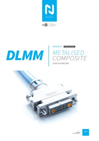
Metalized composite 2mm pitch connector that meets Mil-83513 requirements. Perfect fit for inside the box application with EMI protection need applications: UAV, Defense, Communication, Aerospace.

Empfohlen
Empfohlen
Weitere ähnliche Inhalte
Ähnlich wie Catalog DLMM 2019-Metalized composite 2mm pitch connector that meets Mil-83513 requirements
Ähnlich wie Catalog DLMM 2019-Metalized composite 2mm pitch connector that meets Mil-83513 requirements (20)
Kürzlich hochgeladen
Kürzlich hochgeladen (20)
Catalog DLMM 2019-Metalized composite 2mm pitch connector that meets Mil-83513 requirements
- 1. DLMM METALISED COMPOSITE MIL83513 LIGHT & SHIELDED SPECIFICATIONS C R E A T I V E I N T E R C O N N E C T S O L U T I O N S 2mm pitch _ HARSH ENVIRONMENT
- 2. INTRODUCTION Metalised composite 06 PRODUCT SPECS MIL-DTL-83513G performances 09 PRODUCT CONFIGURATION A: Straight PCB 14 B: 90°PCB 18 C: For cabling 20 D: Pre-wired 24 E: Backshell solution 26 Tooling 30 Who are we 32 WE HELP PEOPLE TO FOLLOW THEIR DREAMS AS AN ENGINEER YOU CAN MAKE HISTORY TOGETHER WE'LL FIND THE BEST SOLUTION 02 I DLMM CONNECTORS SUMMARY WE ARE NICOMATIC _ One of the leading international players in the interconnected solutions market, where innovation & creativity are essential. For us, innovation means being bold. OUR CORE VALUE
- 3. Composite shell, up to 50% weight saving compared to micro-d. No alteration of composite shell Board to board, board to wire, wire to wire, panel mount. A modular solution opti- mized for PCB and panel connection in weight- and-space constrained applications. Metalised body armor, MIL-DTL-83513G performances FROM THE IDEA TO THE FINISHED PRODUCT LIGHT WEIGHT ROBUST & EMI PROOF CORROSION RESISTANCE PCB & PANEL USE → LAUNCHED IN 2018 MOQ: 1. Online CAD models instant delivery EASY DESIGN 4,6...up to 32 positions. Mix, power, signal, coax. FLEXIBILITY Thru-hole type or SMT type SMT COMPLIANT Insertable contact, Awg 30 to 12, or pre-wired CABLING 3 weeks: stocked versions 8 weeks: other versions LEAD TIME Aerospace quality standard AS/EN9100 DLMM DELIVERS LIGHTWEIGHT AND EMI PROTECTION ← INTRODUCTION THE CONNECTOR FOR YOUR NEED FLEXIBILITY CORROSION RESISTANCE THINK ABOUT...
- 5. 04I APPLICATIONSI DMM CONNECTORS EMI PROTECTION HARSH ENVIRONMENTS DLMM CONNECTOR LET'S GO P12
- 6. I INTRODUCTIONI DLMM CONNECTORS06 Metalised composite Weight saving Large EMI protection Corrosion resistance PCB & Panel use Composite solution DLMM Today, Nicomatic can offer you the best of innovation on micro-modular connector mar- ket with the DLMM: a metalised compositeMicro-dtype connec- tor. DLMM is well adapted to flying and ground applications that need miniaturization, EMI protection and weight saving. We all know that every ounce of weight matters in soldier equipment or moving vehicles, especially airborne ones, whether electrical or fuel-powered, to consume less and provide more autonomy. Thanks to its Ultem composite shell, our DLMM is defini- tely lighter than an aluminium connector. It actually weighs down to 50% less than an equivalent micro-d connector. It makes as well the mechanical shell not alterable by corrosion. A copper underlayer gua- rantees high EMI protection tested under radio frequency interferences. It makes it a perfect fit for: ◆ shielded PCB connector needs, avoiding the cost of full equipment shielding ◆ for panel mount needs, to ensure shiel- ding continuity Finally the Nickel metallization acts as a strong body armor to ruggedize the DLMM and ensures salt spray resistance that could alter EMI protection. METALISED COMPOSITE▽ WEIGHT SAVING -50% NICKEL LAYER COPPER LAYER ULTEM™ SHELL 1 2 3 VSMICRO-D
- 7. I DLMM SOLUTIONI DLMM CONNECTORS 07 Other 2 rows shell arrangements are available in 8 weeks. DLMM WITH THESE STOCKED SHELLS ARE AVAILABLE IN 3 WEEKS ← Cu +Ni Size 10 Size 16 Size 22 Size 26 Size 32 1 2 LAYOUT EXAMPLESTOCKED SHELL
- 8. 08 I PRODUCT SPECSI DLMM CONNECTORS
- 9. I DLMM CONNECTORS HIGHEST REQUIREMENTS 09I PRODUCT SPECS PRODUCT SPECS CHALLENGE YOUR LIMITS TIPS ALL OUR ENGINEERS SUPPORT YOU We bring you concrete tips. Saving time, more gains, less stress. Consult our lab test reports which are available on our website ! → services / lab reports WORDS ARE GOOD RESULTS ARE BETTER MIL-DTL-83513G PERFORMANCES ACCORDING TO
- 10. 10 I PRODUCT SPECSI DLMM CONNECTORS Dielectric withstanding voltage sea level Performance Results Magnetic permeability High Frequency contacts performances Mating and unmating force Durability Contact engagement and separation forces Insulation resistance Please refer to the High Frequency (HF) contacts page Signal (LF) contacts: Contact resistance @ 3A: 7.63 mΩ max Power (HP) & Coax (HF) contacts: Contact resistance @ 3A: 1.17 mΩ max Signal (LF) & (HP) contacts: EIA 364-21C Insulation resistance: > 5 GΩ @ 500V Dielectric withstanding voltage high altitude (70 000 ft) EIA-364-20C (Between all adjacent contacts & between the shell and each peripheral contact) (Between all adjacent contacts & between the shell and each peripheral contact) EIA 364-21C EIA 364-06C ASTM A342/A342M EIA 364-13D EIA 364-37B MIL-DTL-83513G §4,5,16 & NICOMATIC requirements for HP & HF EIA 364-29C EIA-364-20C Signal (LF) contacts: Withstanding voltage: 600 VRMS Rated Voltage: 200 VRMS Power (HP) contacts: Withstanding voltage: 800 VRMS Rated Voltage: 267 VRM Signal (LF) contacts: Engagement Force: 1.7 N max Separation Force: 0.2 N min Power (HP) & Coax (HF) contacts: Engagement Force: 5 N max Separation Force: 0.5 N min Signal (LF) contacts: Mating Force: 2.781 N max Unmating Force: 0.2 N min Power (HP) & Coax (HF) contacts: Mating Force: 9.733 N max Unmating Force: 1 N min Signal (LF) contacts: Withstanding voltage: 150 VRMS Rated Voltage: 50 VRMS Power (HP) contacts: Withstanding voltage: 150 VRMS Rated Voltage: 50 VRM Contact resistance Relative magnetic permeability <: 2.0 µ Derating (Current carrying capacity) IEC 60512-5-2 Test 5b DMM Connector with only signal (LF) contacts: Max temperature elevation at 3A @ 25°C: 67°C Max temperature elevation at 2.5A @ 85°C: 28°C DMM Connector with only High Power (HP) contacts: Max temperature elevation at 20A @ 25°C: 61°C Max temperature elevation at 20A @ 85°C: 29°C Contact retention force for Signal (LF) contacts: Initial: > 19.74 After 3 replacements: > 6.83 N Contact retention force for Power (HP) & Coax (HF) contacts: Initial: > 22.27N After 5 replacements: > 22.27N Electrical features Mechanical features Results are the same @initial, After temperature cycling, humi- dity, vibration, shock tests and 500 cycles, After salt spray, After fluid immersion, @end Contact replacement DMM Connector with only signal (LF) contacts: 500 cycles min DMM Connector with signal (LF) and High Power (HP) contacts: 500 cycles min
- 11. I DLMM CONNECTORS 11I PRODUCT SPECS Tests performed are part of MIL-DTL-83513G. Features Standard Results Crimp tensile strength Thermal vacuum outgassing Vibration Total mass loss : TML < 1% of the original mass Max volatile condensable material: CVCM < 0.1% of the original mass AWG 28: > 13.4N / AWG 26: > 22.3N AWG 24: > 35.6N / AWG 22: > 53.4N AWG 20: > 142 N / AWG 18: > 200N EIA 364-08 20 EIA 364-28E TEST CONDITION III&IV EIA 364-32D EIA 364-31B - Method IV MIL-DTL-83513G §4,5,18 Insert retention MIL-DTL-83513G §4,5,19 Rentention: > 50 pounds per square inch (222N per sq.inch) Mechanical features Environmental features DMM Connector with signal (LF) and Power (HP) contacts: MIL-DTL-8313G Test Condition III: [147.1 m/s2 (15 gn) peak] Solvent 1: Isopropyl alcohol, Kerosene (Petroleum ether), Ethylbenzene. Solvent 2: Bioact EC-7R Solvent 3: Ethanolamine, 1-methoxy-2- propanol, Water. It is recommended to use the locking fixing hardware (screws) with the HP and mixed contacts with thread lockfluid Ten cycles, cycle duration: 24 hours (except steps 7a and 7b). Temperature cycling Humidity Fluid immersion Temperature cycling severity: -55°C / +125°C Withstanding voltage sea level after Humidity: 360 Vrms. Insulation resistance after Humidity: >1 GΩ A. Lubricating oil Aircraft turbine engines, synthetic base: 20 hours B. Coolant-dielectric fluid synthetic silicate ester base lubricant (coolanol 25): 1 hour +/- 1 minute. Salt spray (corrosion) 364-26B TEST CONDITION A ASTM E595 (ECSS-Q-ST-70-02C) MIL-STD-202, method 215 EIA 364-29C Duration: 96 hours @35°C / Salt solution concentration: 5% Bath solder T°: 250°C - 10 sResistance to soldering heat Marking performance AWG 16: > 240N / AWG 14: > 412.4N AWG 12: > 565N Results are the same @initial, After temperature cycling, humi- dity, vibration, shock tests and 500 cycles, After salt spray, After fluid immersion, @end TIPS
- 12. 12 I OUR PRODUCTS & P/NI DLMM CONNECTORS
- 13. 13I OUR PRODUCTS & P/N CONFIGURE YOUR SOLUTION BUILD YOUR PART NUMBER DLMM RANGE I DLMM CONNECTORS TIPS ALL OUR ENGINEERS SUPPORT YOU We bring you concrete tips. Save time, gain more value, with less stress.
- 14. 14 I PRODUCT SPECSI DLMM CONNECTORS Straight PCBDLMM Thru hole or SMT terminations PCB from 0.8 to 3.2 mm Racking or locked fixing hardware Mixed layout Free 3D & 2D drawings Put it together on our DLMM product page Feel free to use our builder to check the available configuration → nicomatic.com TIPS Flange & row DL22 Metalised Composite 2rows 1 Male 2 Female -yy number side FIRST 3300DMM Male 3mm 1300DMM Male 3mm 330045 Male 4.5mm 130045 Male 4.5mm 4300DMM Female 3mm 2300DMM Female 3mm 430045 Female 4.5mm 230045 Female 4.5mm zz- number side LAST Gender LF contact type Fixing High power & High frequency contacts Locked fixing Y Thru hole 3mm YL Thru hole 4.5mm D51# Jackpost up to 3.2mm T SMT Male only D55# Jackpost Rear panel 0.5 to 2mm D64# Socket up to 3.2mm D Used if no LF D65# Socket Rear panel 0.5 to 2mm Racked fixing D63# Guide pin High Power contacts ø if Signals (LF) contacts only High Frequency contacts nn Contact number LF contact nbr Part numbering DL222Y20D51 Female A
- 15. I DLMM CONNECTORS 15I STRAIGHT ON PCB PC= 7.2 FOR 2 ROWS REAR PANEL CUTOUT All dimensions are in mm 1.8 PCB LAYOUTS ▷ TRU HOLE ▷ LF CONTACTS SMT ▷ HP OR HF CONTACTS ▷ MIXED 6 12 04 24 16 40 32 14 06 26 18 16 08 28 20 18 10 30 22 20 12 36 28 32 24 22 14 38 30 34 26row = 2 B=Distance between fixings (mm) In term of dimension, a High power (HP) contact or a High frequency (HF) contact, correspond to 4 signal contacts (LF) LF contact number = Dimension table Contacts 01 to 08 positions 04 to 32 positionsLF HF&HP
- 16. → FIXING HARDWARE All fixing hardware is compatible with male and female connectors Rows Rows Code Code Reference Reference D51# D64# D63# D55## D65## 17267 16255 Jackpost Jackpost with rear panel Guide socket with rear panel M2.5 Nut Washer Guide pin Bulk kits for fixing hardware can be delivered on request. Guide socket Description Description Description Description Torque (Nm) Torque (Nm) #= PCB thickness (mm) #= PCB thickness (mm) View View View View #=Rear panel thickness (mm) → SCREW LOCKING FOR THE MOST SECURE CONNECTION → GUIDED FIXING FOR AN ACCURATE ALIGNMENT #=Rear panel thickness (mm) Locked mating Racked mating Ø Ø Ø Ø Ø A A B B C C D D L L L L L 0.8 to 1.6 0.8 to 1.6 0.8 to 1.6 0.8 to 1.6 0.8 to 1.6 1.6 to 3.2 1.6 to 3.2 0.5 0.5 0.4 →D51 →D55D →D64L →D65B →D63 PCB REAR PANEL PCB PCB PCB PCB REAR PANEL 0.4 0.4 1 1 1.5 1.5 2 2 1.6 to 3.2 1.6 to 3.2 1.6 to 3.2 0.80 ø2.70 0.50 ø5 2.0 4 → BULK ACCESSORIES This guidepin is compatible with all guided sockets 16 I PRODUCT SPECSI DLMM CONNECTORS TIPS 1.In case of thicker PCB, we can easily manufacture longer fixings. 2. If one connector is mounted with a jackpost fixing, its mating must be mounted with a jackscrew fixing. 3. If one connector is mounted with guide socket fixing, its mating must be mounted with guide pin. 4. Fixings are delivered mounted on the connector. 5. A controlled torque screw driver kit is available, please refer to the tooling page.
- 17. 18 I PRODUCT SPECSI DLMM CONNECTORS Flange & row DL22 Metalised Composite 2rows 1 Male 2 Female yy number side FIRST 3400DMM Male 3mm 1400DMM Male 3mm 4400DMM Female 3mm 2400DMM Female 3mm zz number side LAST Gender LF contact type Locked fixing Racked fixing V Thru hole 3mm VL Thru hole 4.5mm R SMT D Used if no LF D52# Jackpost up to 3.2mm D68# Socket 2 rows up to 3.2mm D74## Socket rear panel 0.5 to 2mm D56## Jackpost rear panel 0.5 to 2mm High Power contacts ø if Signals (LF) contacts only High Frequency contacts nn Contact number LF contact nbr High power & High frequency contactsFixing TIPS 90° PCB Thru hole or SMT terminations Compact Racking or locked fixing hardware Mixed layout Part numbering DL221V20D52 Male BFree 3D & 2D drawings Put it together on our DLMM product page Feel free to use our builder to check the available configuration → nicomatic.com DLMM REAR PANEL CUTOUT PCB LAYOUTS PC= 7.2 FOR 2 ROWS All dimensions are in mm ▷ HP OR HF CONTACTS▷ LF CONTACTS ▷ MIXED MALE MALE MALE FEMALE FEMALE FEMALE
- 18. I DLMM CONNECTORS 19I 90° ON PCB Dimension table 12 04 24 16 40 32 14 06 26 18 16 08 28 20 18 10 30 22 20 12 36 28 32 24 22 14 38 30 34 26row = 2 B=Distance between fixings (mm) In term of dimension, a High power (HP) contact or a High frequency (HF) contact, correspond to 4 signal contacts (LF) LF contact number = → FIXING HARDWARE All fixing hardware is compatible with male and female connectors RowsCode D56## Jackpost Jackpost with rear panel Description Torque (Nm)Row #= PCB thickness (mm) View#=Rear panel thickness (mm) Locked mating A B C D M M L L L L Ø Ø M M Ø Ø 1.6 to 2.4 1.6 to 2.4 2.4 to 3.2 2.4 to 3.2 2.4 to 3.2 2.4 to 3.2 0.8 to 1.6 0.8 to 1.6 0.8 to 1.6 0.8 to 1.6 1.6 to 2.4 1.6 to 2.4 0.5 0.4 0.4 1 1.5 2 D52# 2 2 → SCREWED LOCKING FOR THE MOST SECURE CONNECTION PCB PCB REAR PANEL →D52L →D56MA RowsCode D74## Guide socket Guide socket with rear panel Description Torque (Nm)Row #= PCB thickness (mm) View#=Rear panel thickness (mm) Racked mating A B C D 0.5 0.4 0.4 1 1.5 2 D68# 2 2 → GUIDED FIXING FOR AN ACCURATE ALIGNMENT PCB PCB REAR PANEL →D68 →D74MD Contacts 01 to 08 positions 04 to 32 positionsLF HF&HP
- 19. I OUR PRODUCTS & P/NI DLMM CONNECTORS Insertable/removable contacts Compatible w/ backpotting For cabling Flange & row 1 Male 2 Female yy number side FIRST zz number side LAST 1320SS 50Ω, RG178 3305 5A 3308 8A 3310 10A 3315 15A 3320 20A 1347ZZ 50Ω, UT47 1324SS 50Ω, RG214 1326SS 50Ω, RG316 DT RG174 1385ZZ 50Ω, UT85 RG405 1326SS-75 75Ω, RG179 2326SS 50Ω, RG316 DT RG174 2385ZZ 50Ω, UT85 RG405 2326SS-75 75Ω, RG179 2320SS 50Ω, RG178 4305 5A 4308 8A 4310 10A 4315 15A 4320 20A 2347ZZ 50Ω, UT47 2324SS 50Ω, RG214 Gender LF contact type Fixing Locked fixing S AWG 24-28 C AWG 22 D51# Jackpost up to 3.2mm nn Contact number E Used if no LF D55# Jackpost Rear panel 0.5 to 2mm D64# Socket up to 3.2mm D53 Jackscrew HEX D61 Jackscrew D65# Socket panel 0.5 to 2mm Racked fixing D63# Guide pin High Power contacts ø if Signals (LF) contacts only Shape Signal contacts (LF) High power (HP) & High frequency (HF) contacts MALE MALE FEMALE FEMALE High frequency contacts DL221SP20D53 Female Racking or locked fixing hardware Mixed layout Part numbering OTHER CONTACTS AVAILABLE Mini flex coax cable Double shielding coax cable please consult us INFO — Contacts are delivered together with the connector CFree 3D & 2D drawings Put it together on our DLMM product page Feel free to use our builder to check the available configuration → nicomatic.com TIPS DL22 Metalised Composite 2rows DLMM 20 P 2mm potting shape
- 20. I DLMM CONNECTORS 21I FOR CABLING REAR PANEL CUTOUT FRONT PANEL CUT PC= 7.2 FOR 2 ROWS All dimensions are in mm Dimension table 12 04 24 16 40 32 14 06 26 18 16 08 28 20 18 10 30 22 20 12 36 28 32 24 22 14 38 30 34 26row = 2 B=Distance between fixings (mm) In term of dimension, a High power (HP) contact or a High frequency (HF) contact, correspond to 4 signal contacts (LF) LF contact number = Contacts 01 to 08 positions 04 to 32 positionsLF HF&HP
- 21. I OUR PRODUCTS & P/NI DLMM CONNECTORS → FIXING HARDWARE All fixing hardware is compatible with male and female connectors RowsCode D51# D55# D76 B51M D53 D61 B53 DXX Jackpost Jackpost to be screwed in a panel Jackscrew for mono backshell Jackpost for mono backshell Jackscrew type ChC Jackscrew Jackpost with rear panel Description Torque (Nm)#=Front panel thickness (mm) View#=Rear panel thickness (mm) Locked mating Ø Ø A B C D L Up to 1.5 Min 1.5 1.5 to 3.2 0.5 0.4 0.3 1 1.5 2 These jackscrews are compatible with all the lock type jackposts No fixing. Also use in case of jackscrewed monobackshell as the fixing is delivered mounted on the backshell → SCREWED LOCKING FOR THE MOST SECURE CONNECTION HEX.2 FRONT PANEL REAR PANEL HEX.2 HEX.2 HEX.4 HEX.4 FRONT PANEL HEX.4 0.80 TIPS In case of a thicker PCB, we can easily manufacture a longer fixing. If one connector is mounted with guide socket fixing, its mating must be mounted with guide pin. 1 3 2 4 5If one connector is mounted with a jackpost fixing, its mating must be mounted with a jackscrew fixing. Fixings are delivered mounted on the connector. A controlled torque screwdriver kit is available, please refer to the tooling page. →D51 →D76 →D55D →B51M →D53 →D61 →B53 →DXX 22
- 22. I DLMM CONNECTORS 23I FOR CABLING RowsCode D64# D65# D77 D63# Guide socket Guide socket to be screwed in a panel Guide pin Guide socket with rear panel Description Torque (Nm) View#=Rear panel thickness (mm) Racked mating Ø Ø Ø A B C D L L Up to 1.5 Up to 1.5 Min 1.5 1.5 to 3.2 1.5 to 3.2 0.5 0.4 0.4 1 1.5 2 Reference Reference 17267 16255M2.5 Nut Washer Bulk kits for fixing hardware can be delivered on request. Description DescriptionOverview View → BULK ACCESSORIES This guide pin is compatible with all the guide socket #=Front panel thickness (mm) → GUIDED FIXING FOR AN ACCURATE ALIGNMENT ø2.702.500.80 0.50 ø5 FRONT PANEL REAR PANEL FRONT PANEL FRONT PANEL 4 →D64L →D77 →D65C →D63
- 23. I OUR PRODUCTS & P/NI DLMM CONNECTORS Pre-Wired Choose your length Backpotting option Metal braid and backshell option Twisted pairs?, different colors?, tinned striped termination? label? shrinkable tube? Braided sleeving? We are well-experienced SIGNAL WIRES: MIL-22759/11 (/18 for AWG22) HIGH POWER WIRES: MIL-22759/11 HIGH FREQUENCY COAXIAL CABLES: MIL-C-17 (RG type) BACK POTTING: STYCAST2651MM + Catalyst V9 METAL BRAID: A-A-A-59569 LENGTH: From 50mm to 5000mm, AVAILABILITY: Check arrangements, shape, fixing hardware OPTIONS Flange & row HDL22 Metalised Composite 2 rows 1 Male 2 Female Gender Fixing Serie 30 contacts number Serie 30 wire & color (HP only) Shielding Config. LengthSignal wire + color # H# AWG 28 P 2mm potting shape I# AWG 26 Q 2mm potting shape + potting HP HF L# AWG 20 M# AWG 18 N# AWG 16 O# AWG 14 P# AWG 12 A RG174 B RG178 C RG178 DT E RG179 DT F RG316 G RG316 DT H RG405 D RG179 J# AWG 24 K# AWG 22 Shape & potting LF contacts nbr nn Contact number -yy Number side FIRST M Mono backshell N Mono backshell +metal braid E If no Signals (LF) contacts R Back to back reversed Zz- Number side FIRST ø if Signals (LF) contacts only Z No F Fly lead B Back to back LLLLPlease refer to "DMM for cabling" fixing hardware page #WIRE COLOR Black Red Yellow Blue Brown Orange Green Violet Grey White 0 6 1 7 2 8 3 9 4 R 5 Rainbow repeated TIPS 3D & 2D drawings for free Please build it on our DMM product page Feel free to use our builder to check the available configuration → nicomatic.com TIPS Part numbering Pre-wired DLMM Female D DLMM 24
- 24. I OUR PRODUCTS & P/NI DLMM CONNECTORS Mono-block Backshell Metalised composite As a rear part of the DLMM they provide → Mechanical protection, thereby avoiding tension on the wires and the contact soldering/crimping 360° shielding against EMI/RFI (according to MIL-STD-1377) with a transfer impedance (Zt) under 5mOhm from 20kHz to 200MHz. Compatibility with Band-it type systems Weight saving → DLMM Type 2 2 rows -3 Jackscrew fixing Mounted on the backshell.* -1 Jackpost fixing B51M Mounted on the connector.* Row Fixing Delivered with Distance between the fixings -L Only signal (LF) -M At least one serie 30 contact (HF or HP) * Please refer to "DLMM for cabling" fixing hardware page 1 Mounted on a male DLMM 2 Mounted on a female DLMM - xx Distance between the fixings -P Mounted on a 2mm potting shape -F Flat band -C Coiled band ø No Connector layout Connector gender Connector shape XX>18 Part numbering DLMM-M Metalised Composite 2rows 7 2.5B=XX Example with B53 Please consult our 3D & 2D drawings Dimension table 24 16 40 32 26 18 28 20 18 10 30 22 20 12 36 28 32 24 22 14 38 30 34 26row = 2 B=Distance between fixings (mm) In term of dimension, a High power (HP) contact or a High frequency (HF) contact, correspond to 4 signal contacts (LF) LF contact number = CHECK OUR TOOLS & ACCESSORIES →NEXT PAGE P.74 26
- 25. 27I DLMM CONNECTORS EXTRA PROTECTION I BACKSHELL
- 26. I OUR PRODUCTS & P/NI DLMM CONNECTORS → ACCESSORIES → TOOLING PLEASE CONSULT OUR DLMM WEBSITE PAGE TO GET A QUOTE PLEASE CONSULT OUR DLMM WEBSITE PAGE TO GET A QUOTE FLAT BAND TOOL FOR MOUNTING/ DISMOUNTING OF MONO BACKSHELL COILED BAND BANDING TOOL KIT Reference _ 17205 Reference _ C17596 Reference _ 17206 Reference _ C17472 28
- 27. 29I DLMM CONNECTORS Please check Our youtube channel Video instructions available ! I BACKSHELL
- 28. I OUR PRODUCTS & P/NI DLMM CONNECTORS ToolingDLMMThe right tool for the right component High reliability → TORQUE CONTROL SCREW DRIVER Reference Reference 18035 18036 C18599 18042 18091 18040 PresetScrewdriver 0.3NM (Blue) PresetScrewdriver 0.4NM (Red) Slot head tip with clearance Internal hex Z tip Slot head tip Description Description ViewOverview Package: Two screwdrivers and 3 bolt tips packaged in box Using this tooling will ensure the quality and precision of all your designs NOTES 30
- 29. 31I DLMM CONNECTORS Please consult on our website crimping instruction ICLF01 Please consult on our website crimping instruction IC30HP02 & IC30HP04. Please consult on our website crimping instruction IC30HF01 & IC30HF02. Reference Reference Reference Reference Reference MH800 16459 C13172 13171 13712 13242 13170 C12935 12368 13858 C14680 MH800C12929 C16460 C13847 K1131 C16462 C14925 C12238 C14770 C12237 Description Description Description Description DescriptionView View View View View → SIGNAL(LF) CONTACT CRIMPING TOOL → HIGH POWER CONTACT(HP) CRIMPING TOOL → SIGNAL(LF) CONTACT INSERTION/EXTRACTION TOOL → HP & HF CONTACT EXTRACTION TOOL CENTRAL CONTACT SLEEVE → HIGH FREQUENCY (HF) CRIMPING TOOL Crimping Hand tool DANIELS MH800 Crimping Hand tool DANIELS AF8 Body driver + Cover cap Extraction tool for High power (HP) & High Fequency (HF) contacts "S" contacts insertion tip "C" contacts insertion tip Male contacts extraction tip Female contacts extraction tip Package: Bolt + driver + tips Crimping Hand tool DANIELS HX3 Dies Hex. 3,25 / 4 Crimping Hand tool DANIELS MH800 Positioner K1692 for signals (LF) contacts Positioner for High Power (HP) contacts Dies Hex. 1,9 / 2,4 / 2,8 Positioner K1692 for High Frequency contacts (HF) Package: Hand tool MH800 + Positioner Package: Hand tool AF8 + Positioner Package: Hand tool HX3 + Dies C13847 Package: Hand tool HX3 + Dies C14680 Package: Hand tool MH800 + Positioner TIPS TIPS TIPS Contact is delivered with an external clip which allows it to be manually inserted into the cavity without tooling.TIPS I TOOLING
- 30. 32 I WHO WE AREI DMM CONNECTORS WHO WE ARE ? WE ARE DREAMERS _ One of leading international players in the interconnect solutions market, where innovation & creativity are core values. For us, innovation means being bold.
- 31. I DMM CONNECTORS 33 HUMAN & TECHNOLOGIC QUALITY WITHOUT COMPROMISE BUSINESS ETHICS WE CARE ABOUT PROGRESS We like to believe that we help users with personal development. Simply because "impossible" is not in our vocabulary. It reflects the high quality products and services of the brand. High standards: excellence cannot be achieved by making concessions. Environmental impacts, healthcare & well-being at work, conflicts minerals declarations, climate impact are a reality. Every day we're challenging ourselves to provide added value to our customers, and we do our best to provide an exceptional and motivating work environment to our team. We honour our promises, they are not just words. Showcasing the know-how of our internal expertise throughout the world. We're working for the world of tomorrow. And you? I WHO WE ARE
- 32. DON’T LET ANYONE TELLYOU THAT YOU CAN’T DO IT BECOME THE BEST VERSION OF YOURSELF
- 33. C R E A T I V E I N T E R C O N N E C T S O L U T I O N S DON’T LET ANYONE TELLYOU THAT YOU CAN’T DO IT BECOME THE BEST VERSION OF YOURSELF
- 34. INNOVATION IS MADE OF A MILLION SECONDS BUT ONLY REVEALED IN ONE C R E A T I V E I N T E R C O N N E C T S O L U T I O N S
- 35. I DLMM CONNECTORS 37 Date of issue: January 2019 Catalogue reference : C.1.0DLMM_EN_XXXX NICOMATIC maintains a policy of ongoing development and improvement. It therefore reserves the right to change design, dimensions and specifications without notice. All information stated inside this catalogue is not contractual and subject to change. (eg. standard connector configurations). Copyright 2019 by NICOMATIC (all rights reserved). I NOTHING IS IMPOSSIBLE
- 36. HEADQUARTER FRANCE T:+33 (0)4 50 36 13 85 france@nicomatic.com MEMBER OF Gifas - Eden Aerospace cluster WEBSITE nicomatic.com CAREER COME & JOIN US ◆ Improving technology ◆ Diversity & gender equality ◆ We promote initiative & responsibility READY TO JOIN OUR TEAM? recruitment@nicomatic.com SUBSIDIARIES UNITED STATES T:+1 21 54 44 95 80 usa@nicomatic.com CHINA T:+86 (0)22 23 85 88 36 china@nicomatic.com INDIA T: +91 80 421 315 74 india@nicomatic.com UNITED KINGDOM T: +44 (0) 11 83 80 10 33 uk@nicomatic.com GERMANY T: +49 (0)33 203 878 801 germany@nicomatic.com TURKEY T: +90 (0) 312 504 37 29 turkey@nicomatic.com SOUTH KOREA T: +82 (0)2 553 6822 korea@nicomatic.com JAPAN T: +81 (0)80 2138 0909 japan@nicomatic.com SINGAPORE T: +65 62 62 12 80 singapore@nicomatic.com CANADA T: +41 (0) 438 885 3395 canada@nicomatic.com TAIWAN T: +886 (0)2 2311 2667 taiwan@nicomatic.com