"I see eyes in my soup": How Delivery Hero implemented the safety system for ...
Jawaban soal-latihan1mekanika
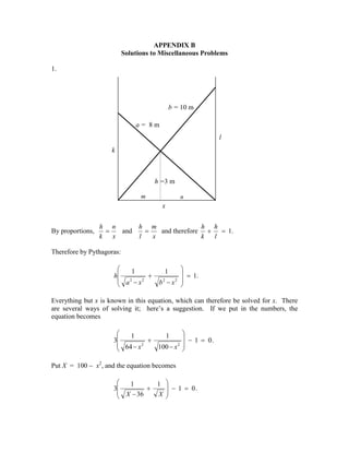
1. APPENDIX B
Solutions to Miscellaneous Problems
1.
b = 10 m
a= 8m
l
k
h =3 m
m
n
x
By proportions,
h n
h m
h h
=
and
=
and therefore +
= 1.
l
x
l
k x
k
Therefore by Pythagoras:
1
h
+
a2 − x2
= 1.
2
2
b −x
1
Everything but x is known in this equation, which can therefore be solved for x. There
are several ways of solving it; here’s a suggestion. If we put in the numbers, the
equation becomes
1
1
3
+
64 − x 2
100 − x 2
− 1 = 0.
Put X = 100 − x2, and the equation becomes
1
1
− 1 = 0.
3
+
X − 36
X
2. This can be written f ( X ) = 3( A + B ) − 1 = 0 , where A and B are obvious functions of
X. Differentiation with respect to X gives f ' ( X ) = − 3 ( A3 + B 3 ) and Newton-Raphson
2
iteration (X = X − f/f') soon gives X, from which it is then found that x = 6.326 182 m.
2.
α
l0
T
ml0sinα.Ω2
*
*
mg
Ω
In the corotating frame the bob is in equilibrium under the action of three forces – its
weight, the tension in the string and the centrifugal force. (If you don’t like rotating
reference frames and centrifugal force, it will be easy for you to do it “properly”.)
Resolve the forces perpendicular to the string: ml0 sin α.Ω 2 . cos α = mg sin α , and the
problem is finished.
3. (a) Raising or lowering the board doesn’t apply any torques to the system, so the
angular momentum L is conserved. That is,
L = ml 2 sin 2 θ . ω is constant.
We also have that
(1)
g = l cos θ . ω.
(2)
i. Eliminate ω from these equations. This gives:
l 3 sin 3 θ tan θ =
which is constant.
L2 ,
gm 2
(3)
3. ii. Eliminate l from equations (1) and (2). This gives:
mg 2 ,
ω cot θ =
L
3
2
(4)
which is constant.
iii. Eliminate θ from equations (1) and (2). This gives:
L
ω3 ωl 2 − = g 2 .
m
(5)
(Check the dimensions of all the equations.) Then we can get L/m from equation (1) and
hence
(
)
ω3 ωl 2 − Ω l02 sin 2 α = g 2 ,
which is constant.
(b) i.
3
l 3 sin 3 θ tan θ = l0 sin 3 α tan α = 0.023 675 m 3 .
Although we are asked to plot θ vertically versus l horizontally, it is easier, when
working out numerical values, to calculate l as a function of θ. That is,
l =
0.287 142 .
sin θ 3 tan θ
(The number in the numerator is the cube root of 0.023675.)
90
80
Semivertical angle, degrees
70
60
50
40
30
20
10
0
0
0.1
0.2
0.3
0.4
0.5
0.6
0.7
Length of string, metres
0.8
0.9
1
4. For l = 40 cm = 0.4 m, the semivertical angle is given by
sin 3 θ tan θ = 0.369 923.
θ = 45o 31'.
The solution to this is
(See section 1.4 of Celestial Mechanics if you need to know how to solve the equation
f(x) = 0.)
ω3 cot 2 θ = Ω 3 cot 2 α .
(b) ii.
With the given data, this is ω3 = 199.385 tan 2 θ .
12
Angular speed, rad s-1
10
8
6
4
2
0
0
(
10
20
30
40
50
Semivertical angle, degrees
)
(
60
)
70
(b) iii.
2
ω3 ωl 2 − Ω l02 sin 2 α = Ω 3 Ωl02 − Ω l02 sin 2 α = Ω 4l0 cos 2 α .
That is,
ω3 (ωl 2 − a ) = g 2 , where, with the given initial data,
a = 0.48168 m2 s−1 and g2 = 96.04 m2 s−4 .
5. Although we are asked to plot ω vertically versus l horizontally, it is easier, when
working out numerical values, to calculate l as a function of ω. That is,
l
2
g2
a
= 4 + .
ω
ω
20
18
Angular speed, rad s -1
16
14
12
10
8
6
4
2
0
0
0.1
0.2
0.3
0.4
0.5
0.6
0.7
Length of string, metres
0.8
0.9
1
To solve the above equation for ω might be slightly easier with the substitution of u for
1/ω:
g 2u 4 + au − l 2 = 0 .
With l = 0.6 m, this gives u = 0.226121 rad−1 s, and hence ω = 4.422 rad s−1. As in part
(b) i, it is necessary to know how to solve the equation f(x) = 0. See section 1.4 of
Celestial Mechanics if you need to know how.
6. 4. There are no horizontal forces, because the table is smooth. Therefore the centre of
mass of the rod falls vertically.
l
θ mg
y
N
x
From energy considerations
1
2
&
my 2 +
(
1 1
2 3
)
&
ml 2 θ 2 + mgy = constant .
(1)
&
&
But y = l cos θ and therefore y = − l sin θ.θ .
â
&
(3 sin 2 θ + 1)l θ2 + 6 g cos θ = C .
(2)
&
Initially θ = θ = 0, ∴ C = 6 g .
â
6 g (1 − cos θ) .
&
θ2 =
l (3 sin 2 θ + 1)
(3)
&
&
&
&
Also, since y 2 = l 2 sin 2 θ θ2 and x 2 = l 2 cos 2 θ θ2 ,
we obtain
&
y2 =
6 gl sin 2 θ(1 − cos θ)
3 sin 2 θ + 1
(4)
7. and
&
x2 =
6 gl cos 2 θ(1 − cos θ)
.
3 sin 2 θ + 1
(5)
&
&
&
Of course θ and y increase monotonically with θ; but x starts and finishes at zero, and
must go through a maximum. With c = cos θ, equation (5) can be written
&
x2 =
6 glc (1 − c) ,
4 − 3c 2
(6)
&
&
and by differentiating x 2 with respect to c, we see that x 2 is greatest at an angle θ given
by
3c 3 − 12c + 8 = 0 ,
(7)
the solution of which is θ = 37 o 50' .
&
If the length of the rod is 1 m (l = 0.5 m) and x = 1 m s−1, equation (6) becomes
26.4c 2 − 29.4c + 4 = 0,
and the two solutions are
(8)
θ = 17 o 15' and 80o 52' .
The reader who has done all the problems so far will be aware of the importance of being
able instantly to solve the equation f(x) = 0. If you have not already done so, you should
write a computer or calculator program that enables you to do this instantly and at a
moment’s notice. See section 1.4 of Celestial Mechanics if you need to know how.
If you want to find the normal reaction N of the table on the lower end of the rod, you
y
could maybe start with the vertical equation of motion m&& = N − mg . Differentiate
&y
&
equation (4): 2 y&& = whatever, and the use equation (4) again for y . This looks like
rather heavy and uninteresting algebra to me, so I shan’t pursue it. There may be a better
way...
8. 5. In the figure below I have marked in red the forces on the rod, namely its weight mg
and the horizontal and vertical components X and Y of the reaction of the hinge on the
rod. I have also marked, in green, the transverse and radial components of the
θ
acceleration of the centre of mass. The transverse component is l&& and the radial
&2.
component is the centripetal acceleration lθ
&
l θ2
l
Y
mg
l&&
θ
θ
*
X
From consideration of the moment of the force mg about the lower end of the rod, it is
evident that the angular acceleration is
&& = 3 g sin θ ,
θ
4l
(1)
& &
&
and by writing && as θ dθ /dθ and integrating (with initial conditions θ = θ = 0 ), or from
θ
energy considerations, we obtain the angular speed:
3 g (1 − cos θ) .
&
θ2 =
2l
(2)
The horizontal and vertical equations of motion are:
&
X = ml (&& cos θ − θ 2 sin θ)
θ
and
(3)
&
mg − Y = ml (&& sin θ + θ2 cos θ).
θ
(4)
(As ever, check the dimensions - and count the dots!)
9. &
After substitution for && and θ2 we find
θ
X = 3 mg sin θ (3 cos θ − 2)
4
Y = 1 mg (1 − 3 cos θ ) 2 .
4
and
(5)
(6)
The results follow immediately.
6. Call the length of the rod 2l. Initially the height above the table of its centre of mass
is l cos 40ο, and its gravitational potential energy is mg l cos 40ο. When it hits the table
at angular speed ω, its kinetic energy is 1 Iω2 = 1 ( 4 ml 2 )ω2 = 2 ml 2 ω2 . Therefore,
2
2 3
3
ω =
3g cos 40O
= 4.746 rad s −1 = 271.9 deg s −1 .
2l
To find the time taken, you can use equation 9.2.10:
t =
I 900
dθ
∫400 E − V (θ) .
2
(7)
Here, I = 4 ml 2 , E = mgl cos 40 o , V (θ) = mgl cos θ and therefore
3
t=
2l
3g
∫
90
dθ
40
o
.
(8)
cos 40 − cos θ
The magnitude of the quantity before the integral sign is 0.184428 s. To find the value of
the integral requires either that you be an expert in elliptic integrals or (more likely and
more useful) that you know how to integrate numerically (see Celestial Mechanics 1.2.)
I make the value of the integral 2.187314, so that the time taken is 0.4034 seconds.
When integrating, note that the value of the integrand is infinite at the lower limit. How
to deal with this difficulty is dealt with in Celestial Mechanics 1.2. It cannot be glossed
over.
10. 7. Here is the diagram. The forces are the weight mg of the rod, and the force of the
table on the rod. However, I have resolved the latter into two components – the normal
reaction N of the table on the rod, and the frictional force F, which may be either to the
left or the right, depending on whether rod is tending to slip towards the right or the left.
The magnitude of F is less than µN as long as the rod is not jus about the slip. When the
rod is just about to slip, F = µN, µ being the coefficient of limiting static friction.
N
mg
θ
F
Just as in Problem 5, the equations of motion, as long as the rod does not slip, are
F = 3 mg sin θ (3 cos θ − 2)
4
(1)
and
N = 1 mg (1 − 3 cos θ ) 2 .
4
(2)
â
3 sin θ (3 cos θ − 2) .
F
=
N
(1 − 3 cos θ) 2
(3)
The figure below shows F/N as a function of θ. One sees that, as the rod falls over, F/N
increases, and, as soon as it attains a value of µ, the rod will slip. We see, however, that
F/N reaches a maximum value, and by calculus we can determine that it reaches a
maximum value of 15 10 / 128 = 0.3706 when θ = cos −1 ( 1 ) = 35o 05'. If µ < 0.3706,
9
the bottom of the rod will slip before θ = 35o 05'. If, however, µ > 0.3706, the rod will
not have slipped by the time θ = 35o 05' , and it is safe for a while as F/N starts to
decrease. When θ reaches cos −1 ( 2 ) = 48o 11' , the frictional force changes sign and
3
thereafter acts to the left. (The frictional force of the table on the rod acts to the left; the
frictional force of the rod on the table acts to the right.) We know by now (since the rod
survived slipping before θ = 35o 05' , that the magnitude of F/N can be at least as large
11. 0.2
0
F/N
-0.2
-0.4
-0.6
-0.8
-1
0
5
10
15
20
25
30
θ, degrees
35
40
45
50
55
as 0.3706, and it doesn’t reach this until θ = 51o 15'. Therefore, if the rod hasn’t slipped
by θ = 35o 05' , it won’t slip before θ = 51o 15'. But after that it is in danger again of
slipping. F/N becomes infinite (N = 0) when θ = cos −1 ( 1 ) = 70 o 31' , so it will certainly
3
slip (to the right) before then.
If µ = 0.25, the rod will slip to the left when
3 sin θ (3 cos θ − 2)
1
= , or θ = 19 o 39' .
2
(1 − 3 cos θ)
4
If µ = 0.75, the rod will slip to the right when
3 sin θ (3 cos θ − 2)
3
= − , or θ = 53o 07' .
2
(1 − 3 cos θ)
4
Again, it is very necessary that you prepare for yourself a program that will instantly
solve the equation f(x) = 0.
12. 8.
N2
P
&
lθ 2
C
l
l&&
θ
mg
N1
θ
O
Let the length of the ladder be 2l. By geometry, the distance OC remains equal to l
throughout the motion; therefore C describes a circle of radius l, centre O. I have
marked in, in green, the radial and transverse components of the acceleration of C,
&
&
namely lθ 2 and l&& . The angular speed of the ladder is θ and the linear speed of the
θ
&
centre of mass C is lθ . I have also marked, in red the three forces acting on the ladder,
namely its weight and the reactions of the floor and the wall on the ladder.
&
The angular speed θ can be obtained from energy considerations. That is, the loss of
potential energy in going from angle α to the vertical to angle θ is equal to the gain in
translational and kinetic energies:
mgl (cos α − cos θ) =
â
1
2
&
m(lθ) 2 +
3g
&
θ2 =
(cos α − cos θ) .
2l
1
2
&
( 1 ml 2 )θ 2 .
2
(1)
The angular acceleration && can be obtained by considering that the total moment of all
θ
forces about P is mgl sin θ , and the rotational inertia is 4 ml 2 :
3
mgl sin θ =
4
3
ml 2&& .
θ
13. The vertical and horizontal equations of motion are:
&
N 2 = m(l&& cos θ − lθ2 sin θ)
θ
&
mg − N1 = m(l&& sin θ + lθ2 cos θ) ,
θ
and
(3)
(4)
although we need only the first of these, because we wish to find out when N2 = 0.
&
On substitution for && and θ2 we find that
θ
N2 =
mg sin θ(3 cos θ − 2 cos α)
(5)
N1 =
and
3
4
1
4
mg (1 − 6 cos α cos θ + 9 cos 2 θ) .
(6)
We need only the first of these to see that N2 becomes zero (and hence the upper end
loses contact with the wall) cos θ = 2 cos α .
3
9.
θ
N2
&
bθ 2
O
C
mg
b&&
θ
N1
14. It will, I think, be agreed that the point O remains fixed in space as long as the
semicylinder remains in contact with wall and floor. Therefore the centre of mass C
moves in a circle around O. We’ll call the radius of the circle, which is the distance
between O and C, b, which, for a semicylinder, equals 4a/(3π) (see Chapter 1), where a is
the radius of the semicylinder. I have marked, in red, the three forces on the
semicylinder, and also, in green, the radial and transverse components of the acceleration.
&
The angular speed θ can be obtained from energy considerations. The gain in kinetic
&
&
energy in going from rest to an angular speed θ is 1 (mk 2 )θ 2 , and the gain in potential
2
energy when the centre of mass drops through a vertical distance b sin θ is mgb sin θ .
Here k is the radius of gyration about O, which, for a semicylinder, is given by
k 2 = 1 a2 .
2
[I have left b and k as they are in the equations, so that the analysis could easily be
adapted, if needed, for a hollow semicylinder, or a solid hemisphere, or a hollow
hemisphere. From Chapters 1 and 2 we recall:
Solid semicylinder:
4a
b=
3π
Hollow semicylinder:
b=
2a
π
k 2 = a2
Solid hemisphere:
b=
3a
8
k2 =
2
5
a2
Hollow hemisphere:
b= a
k =
2
3
2
1
2
k =
2
2
1
2
a
a
2
32
b2
=
2
k
9π 2
b2
4
= 2
2
k
π
45
b2
=
2
k
128
b2 3
=
]
k2 8
On equating the gain in kinetic energy to the loss in potential energy, we obtain
2bg
&
θ 2 = 2 sin θ .
k
(1)
The angular acceleration && can be obtained from applying τ = I&& about O:
θ
θ
mgb cos θ = mk 2&& ,
θ
from which
&& = bg cos θ .
θ
k2
The horizontal and vertical equations of motion are
(2)
15. &
N 2 = mb(θ2 cos θ + && sin θ)
θ
and
(3)
&
N1 − mg = mb(θ2 sin θ − && cos θ) .
θ
(4)
We don’t really need equation (4), because we are trying to determine when N2 = 0.
On substitution from equations (1) and (2), equation (3) becomes
N1 =
6mb 2 g
sin θ cos θ .
a2
(5)
This is zero when θ = 0o (which was the initial condition) or when θ = 90o, at which
point contact with the wall is lost, which it was required to show.
At this instant, the rotational velocity is
2bg
counterclockwise.
k2
and the linear velocity of C is b
2bg
horizontally to the right.
k2
The rotational kinetic energy is
1
2
Iω2 , where ω =
2bg
, and I is the rotational inertia
k2
about the centre of mass, which is m(k 2 − b 2 ) .
â
K rot =
The translational kinetic energy is
â
1
2
K tr =
mbg (k 2 − b 2 ) .
k2
mv 2 , where v =
2bg
.
k2
mb 3 g
.
k2
The sum of these is mbg , which is just equal to the loss of the original potential energy,
which serves as a check on the correctness of our algebra.
There are now no horizontal forces, so the horizontal component of the velocity of C
remains constant. The semicylinder continues to rotate, however, until the rotational
kinetic energy is converted to potential energy and C rises to its maximum height. If the
base then makes an angle φ with the vertical, the gain in potential energy is mbg sin
φ, and equating this to the rotational kinetic energy gives
16. sin φ = 1 − b 2 /k 2 .
This gives the following results:
Solid semicylinder:
φ = 39o 46'
Hollow semicylinder:
φ = 36o 30'
Solid hemisphere:
φ = 40o 25'
Hollow hemisphere:
φ = 38o 41'
R
10.
λ
P
*
mg
α
It is well known that if α > tan −1 µ the particle will slide down the plane unless helped by
an extra force. I have drawn the three forces acting on the particle. Its weight mg. The
reaction R of the plane on the particle; if the particle is in limiting static equilibrium, this
reaction will make an angle λ (“the angle of friction”) with the plane such that tan λ = µ.
It therefore makes an angle α − θ with the vertical. Finally, the additional force P
needed; we do not initially know the direction of this force.
When three (or more) coplanar forces are in equilibrium and are drawn head-to-tail, they
form a closed triangle (polygon). I draw the triangle of forces below.
17. P
R
mg
α−λ
It will be clear from the triangle that P is least when the angle between P and R is 90o:
P
R
mg
α−λ
The least value of P is therefore mg (sin α cos λ − cos α sin λ ) . But tan λ = µ and
µ
1
and cos λ =
.
therefore sin λ =
1+ µ 2
1+ µ 2
â
Pmin =
mg (sin α − µ cos α ) .
1− µ2
18. 11.
&& = && /a
θ s
m, a
I = mk 2
s
&&
x
&&
s
mg
&&
x
M
x
As the cylinder rolls down the plane, the wedge, because its base is smooth, will slide
towards the left. Since there are no external horizontal forces on the system, the centre of
mass of the system will not move horizontally (or, rather, it won’t accelerate
horizontally.)
As usual, we draw a large diagram, using a ruler , and we mark in the forces in red and
the accelerations in green, after which we’ll apply F = ma to the cylinder, or to the
wedge, or to the system as a whole, in two directions. It should be easy and
straightforward.
I have drawn the linear acceleration && of the cylinder down the slope, and its angular
s
&& . I have drawn the linear acceleration && of the wedge, which is also
acceleration θ
x
shared with the cylinder. I have drawn the gravitational force mg on the cylinder. There
is one more force on the cylinder, namely the reaction of the wedge on the cylinder. But
I’m not sure in which direction to draw it. Is it normal to the plane? That would mean
there is no frictional force between the cylinder and the plane. Is that correct
(remembering that both the cylinder and the wedge are accelerating? Of course I could
calculate the moment of the force mg about the point of contact of the cylinder with the
plane, and then I wouldn’t need to concern myself with any forces at that point of contact.
But then that point of contact is not fixed. Oh, dear, I’m getting rather muddled and
unsure of myself.
This problem, in fact, is ideally suited to a lagrangian rather than a newtonian treatment,
and that is what we shall do. Lagrange proudly asserted that it was not necessary to draw
any diagrams in mechanics, because it could all be done analytically. We are not quite
so talented a Lagrange, however, so we still need a large diagram drawn with a ruler.
19. But, instead of marking in the forces and accelerations in red and green, we mark in the
velocities in blue.
& &
θ = s /a
m, a
I = mk 2
s
&
x
&
s
mg
&
x
M
x
No frictional or other nonconservative forces do any work, so we can use Lagrange’s
∂V
d ∂T ∂T
− = −
equations of motion for a conservative holonomic system;
∂q ∂q
∂q .
dt &
&
The speed of the wedge is x and the speed of the centre of mass of the cylinder is
&
&
&&
&
s 2 + x 2 − 2 sx cos α , and the angular speed of the cylinder is s /a .
The kinetic energy of the system is
2
&
&
&&
T = 1 m( s 2 + x 2 − 2 sx cos α ) +
2
or
T =
1
2
1
2
&
s
&
(mka 2 ) + 1 Mx 2 ,
2
a
k2
&
&&
&
m1 + 2 s 2 − msx cos α + 1 (m + M ) x 2 ,
2
a
and the potential energy is
V = constant − mgs sin α .
Application of Lagrange’s equation to the coordinate x gives us
20. m&& cos α = (m + M ) &&
s
x
and application of Lagrange’s equation to the coordinate s gives us
k2
1 + 2 && = && cos α + g sin α .
s
x
a
Elimination of && from these two equations gives us
s
&& =
x
mg sin α cos α
.
k2
2
(m + M )1 + 2 − m cos α
a
s&
You can also easily find an expression for & is you wish.
If the wedge had been fixed and immovable, and not free to slide on a smooth table, you
would easily have been able to obtain & by newtonian methods. If you put M = ∞ in the
s&
expression for & for the smooth table, do you get the same as you do for the immovable
s&
wedge? (You should do.)
Now that you have found && , you can also find & and && . You therefore now know the
x
s&
θ
magnitude and direction of the velocity of the centre of mass of the cylinder. From this
you should be able to find the net force and torque on the cylinder, and from these, you
should be able to find the magnitude and direction of the reaction of the wedge on the
cylinder. I have not pursued this. If anyone succeeds in doing so, and would like his/her
solution poster here, with acknowledgment, let me know.
21. x
12.
V0
y
α
ψ
s
F
N
*
mg
α
There is no acceleration normal to the plane, and therefore N = mg cos α . The frictional
force F acts along the tangent to the path and is equal to µN, or µmg cos α, where µ is the
22. coefficient of moving friction. We are told to ignore the difference between the
coefficients of moving and limiting static friction. Since the particle was originally at
rest in limiting static friction, we must have µ = tan α. Therefore F = mgsin α . The
tangential equation of motion is
m&& = − F + whatever the component of mg is in the tangential direction in the sloping
s
plane.
The component of mg down the plane would be (look at the left hand drawing) mg sin
α, and so its tangential component (look at the right hand drawing) is mg sin α sin ψ . So
we have, for the tangential equation of motion,
m&& = − mg sin α + mg sin α sin ψ ,
s
or
& = − g sin α (1 − sin ψ ).
s&
We are seeking a relation between V and ψ, so, in the now familiar fashion, we write
dV
V
for && , so the tangential equation of motion is
s
ds
V
dV
= − g sin α (1 − sin ψ ).
ds
(1)
We also need the equation of motion normal to the trajectory. The component of mg in
that direction is mg sin α cos ψ , and so the normal equation of motion is
mV 2
= mg sin α cos ψ .
ρ
Here ρ is the radius of curvature of the path, which is the reciprocal of the curvature
ds / dψ . The normal equation of motion is therefore
V2
dψ
= g sin α cos ψ .
ds
(2)
Divide equation (1) by equation (2) to eliminate s and thus get a desired differential
equation between V and ψ:
1 dV
(1 − sin ψ ) .
= −
V dψ
cos ψ
(3)
This is easily integrated; a convenient (not the only) way is to multiply top and bottom by
1 + sin ψ. In any case we soon arrive at
23. ln V = − ln(1 + sin ψ ) + constant ,
(4)
and with the initial condition V = V0 when ψ = 0, this becomes
V =
V0
.
1 + sin ψ
(5)
In the limit, as ψ → 90ο, V → 1 V0 . The particle is then moving at constant velocity
2
and is in equilibrium under the forces acting upon it just when it was initially at rest.
13. M1 = mass of complete sphere of radius a.
M2 = mass of missing inner sphere of radius xa.
M = mass of given hollow sphere.
M = M 2 − M 1 and M 2 /M 1 = x 3 ,
We have
M1 =
M
Mx 3 .
and M 2 =
1− x3
1− x3
Also
I =
Hence
I = 2 Ma 2 ×
5
If x = 0, I =
show that I →
14.
2
5
2
5
M 1a 2 − 2 M 2 x 2 a 2 =
5
2
5
a 2 ( M 1 − M 2 x 2 ).
1 − x5 .
1 − x3
Ma 2 , as expected. If x → 1, you may have to use de l’Hôpital’s rule to
2
3
Ma 2 , as expected.
M1 = mass of mantle.
M2 = mass of core
M = mass of entire planet.
We have M = M 1 + M 2 and
M2
and therefore
x3
= M × 3
x + s (1 − x 3 )
M1
s (1 − x 3 ) ,
=
and therefore
M2
x3
and
s (1 − x 3 )
.
M1 = M × 3
x + s (1 − x 3 )
24. I = I core + I mantle =
Also
2
5
2
M 2 x 2 a 2 + 5 M 1a 2 ×
1 − x5 ,
1 − x3
where I have made use of the result from the previous problem. On substitution of the
expressions for M1 and M2, we quickly obtain
s + (1 − s ) x 5 .
I = Ma ×
s + (1 − s ) x 3
2
5
2
(1)
A hollow planet would correspond to 1/s = 0. Divide top and bottom by s and it is
immediately seen that the expression for a hollow planet would be identical to the
expression obtained for the previous problem.
1
0.8
0.9
0.6
0.4
0.8
Moment of inertia
0.7
s = 0.2
0.6
0.5
0.4
0.3
0.2
0.1
0
0
0.1
0.2
0.3
0.4
0.5
0.6
Core size
0.7
0.8
0.9
1
Note that both x = 0 and x = 1 correspond to a uniform sphere, so that in either case,
I = 2 Ma 2 ; for all other cases, the moment of inertia is less than 2 Ma 2 .
5
5
The core size for minimum moment of inertia is easily found by differentiation of the
above expression for I, and the required expression follows after some algebra. For s =
0.6, the equation becomes 9 − 15 x 2 − 4 x 5 = 0, of which the only positive real root is
x = 0.736 382, which corresponds to a moment of inertia of 0.90376 % 2 Ma 2 . Note
5
that. for s = 0.6, the moment of inertia, expressed in units of
2
5
Ma 2 , varies very little as
25. the core size goes from 0 to 1, so that measurement of the moment of inertia places very
little restriction on the possible core size.
The inverse of equation (1) is
(1 − s ) x 5 − I (1 − s ) x 3 + (1 − I ) s = 0 ,
(2)
where I is expressed in units of 2 Ma 2 . For I = 0.911, there are two positive real roots
5
(look at the graph); they are x = 0.64753 and 0.81523. For I = 0.929, the roots are
0.55589 and 0.87863. Thus the core size could be anything between 0.55589 and
0.64753 or between 0.81523 and 0.87863 a rather large range of uncertainty. Even if I
were known exactly (which does not happen in science), there would be two solutions for
x.
15. This is just a matter of geometry. If, when you make a small angular displacement,
you raise the centre of mass of the brick the equilibrium is stable. For, while the brick is
in its vertical position, it is evidently at a potential minimum, and you have to do work to
raise the centre of mass. If, on the other hand, your action in making a small angular
displacement results in a lowering of the centre of mass, the equilibrium is unstable.
When the brick is in its vertical position, the height h0 of its centre of mass above the
base of the semicylinder is just
h0 = R + l .
When it is displaced from the vertical by an angle θ, the point of contact between brick
and semicylinder is displaced by a distance Rθ, and, by inspection of the drawing, the
new height h is
h = R cos θ + Rθ sin θ + l cos θ .
â
h − h0 = Rθ sin θ − ( R + l )(1 − cos θ) .
If you Maclaurin expand this as far as θ2, you arrive at
h − h0 ≈
1
2
( R − l )θ 2 .
This is positive, and therefore the equilibrium is stable, if l < R , or 2l < 2R , i.e. if the
length of the brick is less than the diameter of the semicylinder.
27. 16. As in the previous question, it is just a matter of geometry. If rolling the Thing
results in raising its centre of mass, the equilibrium is stable. Initially, the height of the
centre of mass is h0 = b + l.
l
φ
a
b
θ
After rolling, the dashed line, which joins the centres and is of length a + b, makes an
angle θ with the vertical. The short line joining the centre of mass of the Thing to the
centre of curvature of its bottom is of length l − a and it makes an angle θ + φ with the
vertical. The height of the centre of mass is therefore now
h = (a + b) cos θ + (l − a ) cos(θ + φ) .
The centre of mass has therefore rise through a height
h − h0 = (a + b) cos θ + (l − a) cos(θ + φ) − b − l .
Also, the two angles are related by aφ = bθ, so that
28. h − h0 = (a + b) cos θ + (l − a) cos[{1 + (b /a )}θ] − b − l .
Maclaurin expand the cosines to θ2 and you should get
h − h0 = − 1 θ 2 [a + b + (l − a )(1 + b /a ) 2 ] .
2
For stability this must be positive, and hence
1
1
1
>
+ .
a
b
l
If a = b, this becomes l < 1 a .
2
For a hollow semicylinder, l = (1 − 2 /π) a = 0.363a.
â Stable
For a hollow hemisphere, l = 0.5a.
â Borderline stable
For a solid semicylinder,
l = [1 − 4 /(3π)] a = 0.576a.
â Unstable
For a solid hemisphere,
l =
â Unstable
5
8
a = 0.625a.
17. We need to find the height h of the centre of mass above the level of the pegs as a
function of θ . See drawing on next page.
Angles:
BAC = 45o − θ
ΑΒΧ = 45o + θ
Distances:
AB = 2ac
AC = 2ac cos (45o − θ)
EF = 2ac cos (45o − θ) cos (45o + θ) = ac cos 2θ
DC = a 2
DF = a 2 cos θ
h = DF − EF = a ( 2 cos θ − c cos 2θ)
h0 = height of centre of mass above pegs when θ = 0o = a ( 2 − c)
y =
h
=
h0
2 cos θ − c cos 2θ
2 −c
dy/dθ will show that maxima and minima of y ( and of the potential energy), and hence
equilibria, occur for θ = 0o and for cos θ = 1 /(c 8 ) , which is possible only if c > 1 / 8 .
29. A second differentiation will show which extrema are maxima and which are minima. In
particular the second derivative at θ = 0o is zero for c = 1 / 8 . I draw graphs of y : θ for
several c below.
If c = 1 , θ = 45o .
2
θ
D
h
A
*
E
F
B
*
C
31. There are three forces acting on the hemisphere: Its weight mg. The reaction N of the
wall, which is perpendicular to the wall since the wall is smooth. The reaction R of the
floor, which acts at an angle λ to the floor, where µ = tan λ. Three forces in equilibrium
must act through a point; therefore all three forces act through the point P. It is thus clear
that
OP aµ 8µ
.
= 3 =
sin θ =
OC 8 a
3
3
3
If µ = 1 , θ = 41o 48'. If µ = 8 , θ = 90 o . If µ > 8 , the hemisphere can rest in any
4
position, the equilibrium not being limiting static equilibrium.
19.
C
aθ
P
mg
θ
When the rod makes an angle θ to the horizontal, the distance from its centre of mass C
2
to the point of contact P is aθ. The moment of inertia about P is 1 ml 2 + m(al ) . The
3
torque about P is mgaθ cos θ. The equation of motion is
m( 1 l 2 + a 2θ 2 ) && = − mgaθ cos θ .
θ
3
To first order in θ, cos θ ≈ 1 and a 2 θ 2 << 1 l 2 . Therefore, to first order, the equation of
3
motion is
l && = − gaθ
θ
1 2
3
32. P=
and so the period is
2πl .
3ga
20.
O
θ
3
8
x
a
C
a
b
mg
φ
A
I have drawn only one force. I am going to consider the rotational equation of motion
about A, so I shan’t be concerned with the force at A. The equation of motion about A is
I && = − mgx ,
φ
where I is the moment of inertia about A. The moments of inertia about O, C and A,
respectively:
2
5
ma 2 ,
2
5
3
ma 2 − m( 8 a ) ,
2
2
5
3
ma 2 − m( 8 a ) + mb 2 ,
2
where I have made good use of the parallel axes theorem. The distance b is given by the
cosine rule to triangle OCA, and hence we find, after a little algebra, for the moment of
inertia about A:
I = ma 2 ( 7 − 3 cos θ) .
5
4
We also need
33. x=
3a sin θ ,
8
and hence we obtain for the equation of motion
a(56 − 30 cos θ) && = − 15 g sin θ .
φ
For small angles, this becomes
26 a && = − 15 g θ .
φ
From the sine rule we have
sin φ
sin(θ + φ)
=
,
3
a
8a
3
and replacing the sines by the angles, for small angles, we find that φ ≈ 5 θ . Thus the
equation of motion becomes
26 a && = − 25 g θ
θ
and so the period is
P = 2π
26a .
25 g
The (second) moment of inertia with respect to the centre (see chapter 2.19 of
chapter 2) is
a
I centre = 4π ρ0 ∫ (r 4 − r 5 / a)dr =
0
2
15
π ρ0 a 5 .
The moment of inertia with respect to an axis through the centre is 2/3 of this:
I axis =
â
4
45
πρ 0 a 5 .
I axis =
4
15
Ma 2 .
34. 22.
N1
*
N1 = mg cos(α − θ)
F1 = µN1
F1
T
mg
N 2 = mg cos(α + θ)
T + F2
*
α−θ
α+θ
F2 = µN 2
N2
mg
Left-hand particle:
T = mg [µ cos( α − θ) + sin( α − θ)] .
Right-hand particle:
T = mg [sin( α + θ) − µ cos( α + θ)] .
â
µ[cos( α − θ) + cos( α + θ)] = sin( α + θ) − sin( α − θ),
and, by the “sum and difference” trigonometrical formulae, we obtain
2µ cos α cos θ = 2 cos α sin θ,
from which
23.
tan θ = µ.
T + δT
µδN
δN
T
δθ
35. Consider a portion of the rope between θ and δθ. There are four forces on this portion.
The tension T at θ. The tension T + δT at θ + δθ (δT is negative). The normal
reaction δN of the cylinder on the rope. The frictional force µδN of the cylinder on the
rope. Note that the rope is about to slip downwards, so the friction force is upwards as
shown.
δN = (2T + δT ) sin( 1 θ)
2
We have
and
(T + δT ) cos( 1 δθ) + µ δN = T cos( 1 δθ) .
2
2
To first order, these become
δN = T δθ
and
δT = − µ δN .
â
δT = − µT δθ
F = Mg e − µα .
and hence by integration
24
2ax
*
X'-axis
θ
2a(x + y − 1)
C*
*
H
2ay
Y '-axis
36. . Area of square
Area of rectangle
Area of triangle
Area of trapezoid
=
=
=
=
4a 2
4a 2 (1 − x )
2a 2 ( x + y − 1)
2a 2 (1 − x + y )
The weight of the cube is 8a3ρsg, and it acts downward through C, the centre of
mass. The hydrostatic upthrust is 4a3(1 − x + y)ρg and it acts upward through the
centre of buoyancy H. Here ρ is the density of the fluid, and ρs is the density of
the wood. We evidently must find the X'- coordinate of C and of H. Let’s first of
all find the X- and Y- coordinates (see the next figure).
The X- and Y- coordinates of C are trivial and quite easy respectively:
XC = a
YC = a(1 − 2 x)
You are going to have to work quite hard at it to find the X- and Y- coordinates of
H, the centre of buoyancy, which is the centroid of the trapezoid. “After some
algebra” you should find
XH =
2(1 − x + 2 y )a
3(1 − x + y )
YH =
2(2 − 4 x + 2 y + 2 x 2 − 2 xy − y 2 )a
3(1 − x + y )
X-axis
C*
Y-axis
*H
37. To find the X '- coordinates of C and of H, we use the usual formulas for rotation
of axes, being sure to get it the right way round:
X ' cos θ
=
Y ' sin θ
− sin θ X
,
cos θ Y
tan θ = x + y − 1.
together with
Take moments about the axle (origin):
8a 3ρsgX 'C = 4a 3ρg (1 − x + y ).
After a little more algebra, you should eventually arrive at
s =
3 − 7 x + 2 y + 6 x 2 − 3 y 2 − 2 x 3 + y 3 + 3xy 2 .
3(2 − 3x − y + 2 x 2 + 2 xy )
25.
φ
b
F
a
θ
N
Mg
38. Let the radii of the cylinder and sphere be a and b respectively, and the mass of the
sphere be M. The angles θ and φ are related by aθ = bφ. I have drawn the three forces
on the sphere, namely its weight, the normal reaction of the cylinder on the sphere, and
the frictional force on the sphere. The transverse acceleration of the centre of the sphere
&
is (a + b)&& and the centripetal acceleration is (a + b)θ 2 . The equations of motion are:
θ
Mg sin θ − F = M (a + b)&&
θ
and
(1)
&
Mg cos θ − N = M (a + b)θ 2 .
(2)
The angular acceleration of the sphere about its centre is && + && = (1 + a / b)&& , and its
θ φ
θ
2
rotational inertia is 2Mb /5. The torque that is causing this angular acceleration is Fb,
and therefore the rotational equation of motion is
Fb =
2
5
Mb 2 (1 + a / b)&& .
θ
(3)
Elimination of F between equations (1) and (3) yields
&& =
θ
5g
sin θ .
7(a + b)
(4)
& &
&
Write && as θ dθ /dθ in the usual way and integrate with initial conditions θ = θ = 0 , or
θ
from energy considerations:
&
θ2 =
10 g
(1 − cos θ) .
7(a + b)
(5)
&
θ
Substitute for && and θ2 into equation (2) to obtain
N = Mg (17 cos θ − 10) .
(6)
This is zero, and the sphere leaves the cylinder, when cos θ = 10/17, θ = 53o 58' .
39. 26.
12 cm
•
θ
9 cm
Surface density = σ g cm−2
Original sandwich:
Mass = 54σ g
x-coordinate of centre of mass = 3 cm
y-coordinate of centre of mass = 4 cm
Bite:
Mass =
1
2
π32 σ =14.137 166 94σ g
Distance of centre of mass from hypotenuse =
x-coordinate of centre of mass = 4.5 −
4
4
= 1.273 239 545 cm
×3 =
3π
π
4
16
= 3.481 408 364 cm
sin θ = 4.5 −
π
5π
40. y-coordinate of centre of mass = 6 −
4
12
cos θ = 6 −
π
5π
= 5.236 056 273 cm
Remainder:
Mass = (54 − 14.137 166 94)σ = 39.862 833 06σ g
x-coordinate of centre of mass = x
y-coordinate of centre of mass = y
Moments:
39.862 833 06 x + 14.137 166 94 × 3.481 408 364 = 54 × 3.
x = 2.829 270 780 cm
39.862 833 06 y + 14.137 166 94 × 5.236 056 273 = 53 × 4.
y = 3.561 638 436 cm
This point is very close to the edge of the bite. The centre of the bite is at (4.5, 6), and its
radius is 3. Its equation is therefore
( x − 4.5) 2 + ( y − 6) 2 = 9, or x 2 + y 2 − 9 x − 12 y + 47.25 = 0.
The line x = 2.829 270 780 cuts the circle where y 2 − 12 y + 29.791 336 13 = 0 . The
lower of the two points of intersection is at y = 3.508 280 941 cm. The centre of mass is
slightly higher than this and is therefore just inside the bite.
27.
δF
θ
T
T
41. m δθ .
When the band is
2π
spinning at angular speed ω and its radius is r, the centrifugal force on that portion is
mrω2 δθ .
δF =
(I leave it to the philosophers and the schoolteachers to debate as to
2π
whether there “really” is “such thing” as centrifugal force – I want to get this problem
done, and I’m referring to a co-rotating frame.) The y-component of this force is
mrω2 cos θ δθ .
Also, the tension in the band when its radius is r is T = 2πk(r − a).
2π
Consider a portion of the band within the angle δθ. Its mass is
Consider the equilibrium of half of the band. The y-component of the centrifugal force
mrω2 + π
mrω2
2
on it is
cos θ dθ =
. The opposing force is 2T = 4πk(r − a). Equating
2
π
2π ∫− π
4π 2 k ( r − a ) .
these gives ω2 =
mr
28.
Let the distance AB be l and the distance AC be c. Let the mass of the rod be m.
P
A
F
x
C
B
δx
δf
Consider an elemental portion δx of the rod at P at a distance x from A. Its weight is
m δx .
When the rod is about to move, it will experience a frictional force
l
µmg δx ,
which will be in the direction shown if P is to the left of C, and in the
δf =
l
opposite direction if P is to the right of C. When the rod is just about to move (but has not
yet done so) it is still in equilibrium. Consider the moment about A of the frictional
forces on the rod. The clockwise moment of the frictional forces on AC must equal the
counterclockwise moment of the frictional forces on CB. Thus
42. µmg
l
∫
c
0
x dx =
µmg
l
∫
l
c
x dx .
c = l / 2.
â
The net force on the rod is
µmg
l
and this is zero, and therefore
F −
F =
∫
c
0
dx +
µmg
l
µmg ( 2c − l )
=
l
(
l
∫ dx ,
c
)
2 − 1 µmg .
29. The cone slips when tan θ > µ.
It tips when C (the centre of mass) is to the left of M.
The distance OC is h/4. (See Chapter 1, section 1.7). Therefore it tips when tan θ > 4a / h.
Thus it slips if µ < 4a / h and it tips if µ > 4a / h .
C
•
O
M
θ
43. 30.
2a
K
x
λ
A
When the block is just about to tip, the reaction of the table on the block acts at A and it
is directed towards the point K, because, when three coplanar forces are in equilibrium
they must act through a single point. The angle λ is given by tan λ = a/x. However, by
the usual laws of friction, the block will slip as soon as tan λ = µ. Thus the block will
slip if µ < a/x, and it will tip if µ > a/x. Expressed otherwise, it will slip if x < a/µ and
it will tip if x > a/µ. The greatest possible value of x is 2a; therefore the block will
inevitably slip if µ < ½.
31.
τ
R
θ
mg
2ka
θ
When or if the cylinder is just about to tip, it is about to lose contact with the left hand
peg. The only forces on the cylinder are the torque, the weight, and the reaction R of the
right hand peg on the cylinder, which must be vertical and equal to mg. But the greatest
possible angle that the reaction R can make with the surface of the cylinder is the angle of
44. friction λ given by tan λ = µ. From geometry, we see that sin θ = k, or
tan θ = k / 1 − k 2 . Thus the cylinder will slip before it tips if µ < k / 1 − k 2 and it
will tip before it slips if µ > k / 1 − k 2 .
If the cylinder tips (which it will do if µ > k / 1 − k 2 ), the clockwise torque τ at that
moment will equal the counterclockwise torque of the couple (R and mg), which is mgka.
Thus the torque when the cylinder tips is
τ = mgak .
TIP:
(1)
τ
N1
θ
mg
N2
µN2
2ka
µN1
When or if the cylinder is just about to slip, the forces are as shown above, in which I
have resolved the reactions of the pegs on the cylinder into a normal reaction (towards
the axis of the cylinder) and a frictional force, which, when slipping is about to occur, is
equal to µ times the normal reaction. The equilibrium conditions are
µ( N1 + N 2 ) cos θ + ( N1 − N 2 ) sin θ = 0 ,
µ( N1 − N 2 ) sin θ − ( N1 + N 2 ) cos θ + mg = 0
and
µ ( N1 + N 2 ) a = τ .
We can find N1 + N2 by eliminating N1 − N2 from the first two equations, and then,
writing 1 − k 2 for cos θ, we find that, when slipping is about to occur,
45. τ = mga ×
SLIP
µ
1
.
×
2
1+ µ
1 − k2
(2)
I have drawn below the functions
τ
τ
= k (tip) and
=
mga
mga
µ
1
×
(slip)
2
1+µ
1 − k2
for k = 0.1, 0.3, 0.5, 1 / 2 and 0.9. The horizontal lines are the tip functions, and the
curves are the slip functions. As long as µ < k / 1 − k 2 the cylinder will slip. As soon
as µ > k / 1 − k 2 the cylinder will tip.
1.2
k
1
0.9
torque/(mga)
0.8
1/√2
0.6
0.5
0.4
0.3
0.2
0.1
0
0
0.5
1
1.5
µ
2
2.5
3
46. 32.
•
mv2/R
mg
h
N2
N1
F1
F2
2d
We’ll leave to the philosophers the question as to whether centrifugal force “really
exists”, and we’ll work in a co-rotating reference frame, so that the car, when referred to
that frame, is in static equilibrium under the six forces shown. Clearly, N1 and N2 = mg
and F1 + F2 = mv2/R.
The car slips when F1 + F2 = µ(N1 + N2); that is, when v = µgR .
The car tips when mv 2 h / R = mgd ; that is, when v =
dgR / h .
That is, it will slip or tip according as to whether µ < d/h or > d/h.
For example suppose d = 60 cm, h = 80 cm, g = 9.8 m s−2, R = 30 m, µ = 0.8.
In that case, d/h = 0.75, so it will tip at v = 14.8 m s−1 = 53.5 km hr−1.
But if it rains, reducing µ to 0.7, it will slip at v = 14.3 m s−1 = 51.6 km hr−1 .