SlideShare ist ein Scribd-Unternehmen logo
1 von 11
Downloaden Sie, um offline zu lesen
RECEIVER SIDE COMPONENTS DESCRIPTION USING MATLAB (SAMPLE ASSIGNMENT)
For any Help with Receiver Side Components Description Assignment
upload your Homework Assignment by clicking at “Submit Your
Assignment “ button or you can email it to
info@matlabassignmentexperts.com .To talk to our Online Receiver Side
components description Project Tutors you can call at +1 5208371215 or
use our Live Chat option.
Manchester Receiver
This sample assignment shows how to use the HDL Verifier to design, test, and verify a VHDL Manchester Receiver
model with clock recovery capabilities.
Background on Manchester Encoding
Transmission of digital data frequently requires some form of modulation to overcome limits in a physical signal
channel. One technique used for modulating digital data is Manchester Encoding. This technique has the following
useful characteristics:
 The transmit clock signal can be easily extracted from the received data.
 The encoded signal never produces frequency components near DC, regardless of the data, which is useful for
transmission over channels that require AC coupling.
 The encoding circuit is very simple and stateless.
On the negative side, Manchester coding requires substantial bandwidth (above the Shannon limit), which tends to
limit its usefulness in wireless applications. However, for connected applications such as short haul Optical fiber and
Ethernet, it is frequently a good solution.
The following sections discuss:
 The Encoding
 The Receiver
 Decoding with Inphase and Quadrature Convolution
The Encoding
Manchester Encoding involves a transmitter that encodes clock and data signals in a synchronous bit stream, such
that each bit represents a signal transition. The following table shows how each bit setting is defined for an encoding:
Transitions in the Manchester Encoding occur at the center and beginning of each bit. The transition at the center is
defined by the bit value, while the transition at the beginning is dependent on the value of the previous bit. Consider
the following diagram:
As the preceding Manchester encoded signals shows:
 The value of 1 for the first bit forces a high-to-low transition at the center of that bit.
 The value of 0 for the second bit forces a low-to-high transition at the center of that bit and, because the first bit
transitioned from high-to-low, no transition occurs at the start of that bit.
 The value of 0 for the third bit forces a low-to-high transition at the center of that bit and because the second bit
transitioned from low-to-high, a high-to-low transition occurs at the start of that bit.
 The value of 1 for the fourth bit forces a high-to-low transition at the center of that bit and, because the third bit
transitioned from low-to-high, no transition occurs at the start of that bit.
 The value of 0 for the fifth bit forces a low-to-high transition at the center of that bit and, because the fourth bit
transitioned from high-to-low, no transition occurs at the start of that bit.
The Receiver
A device that receives the encoded bit stream is responsible for decoding the bit stream by separating the clock and
data information. In most cases, the receiver must retrieve the original data stream by using only the encoded signal.
This simplifies the communications channel, but means the receiver must overcome the following:
 Differences between the clock used to encode the signal and the clock in the receiver (see the figure below).
 The two clocks can be close in frequency, but small frequency errors occur.
 The phase between the clocks will be arbitrary.
The Manchester Receiver example validates the computations performed by a Manchester Receiver device that is
modeled in VHDL and simulated in ModelSim. Numerous approaches are available for implementing a Manchester
receiver. This example uses a Delay Lock Loop (DLL) that requires the receiver to use a clock that is very close in
frequency to the transmit clock. This results in a simple clock recovery circuit that has a limited frequency lock range.
The receiver over-samples the received data stream at 16 times the data rate. Thus, the receive clock must have a
nominal period of 1/16th the data period. To compensate for minor differences between the transmitting and receiving
clocks or drifts in the channel delay, the receiver adjusts its data period by up to one clock cycle (+/-) per data period.
Thus, the receiver can use 15, 16 or 17 clock cycles to recover the data encoded from the incoming sampled signal.
For example, if the receiver clock is slightly faster then the transmitter clock (frequency error), the receive cycle
occasionally needs to add an extra clock cycle to compensate.
Large sudden phase errors, such as those that occur at startup time, require multiple data periods to acquire a good
lock on the signal. By limiting the maximum phase correction to 1/16th of the total data period, the receiver can be
slow to correct large phase errors.
Decoding with Inphase and Quadrature Convolution
Decoding a received Manchester signal can occur in several ways, but the approach taken in this example is to
consider Manchester Encoding as a digital phase modulation with two symbols: +180 and -180 degrees. By
convolving the incoming signal with a reference inphase (I) and quadrature (Q) waveform at the modulation
frequency, it is possible to extract the data and retrieve information about any phase errors in the received waveform.
After one data cycle, the receiver computes two values (referred to as Isum and Qsum in the VHDL code), which are
measurements of the I/Q convolution value. The receiver then decodes the values to predict:
 The original transmitted data value for the cycle
 An estimate of the phase error between the incoming signal and the receiver's data period
A critical aspect of this design is the interpretation of the I/Q convolution values. At the end of a data receive cycle,
the receiver translates the I/Q values into an estimate of the transmitted data and phase error. One way to present
this information is to show these interpretations as plots versus measured I/Q values.
Data is considered invalid if the measured I and Q are completely ambiguous about the encoded data value.
In a similar way, you can generate an I/Q mapping of the phase correction value in plot format. Such a plot gives a
visual representation of the decoding block. In practice, the details of this mapping have strong impact on the stability
and performance of the Manchester receiver.
In the ideal case where the receiver is perfectly locked to the incoming waveform, the receive cycle is 16 cycles long
and the measured I/Q convolution values are fairly easy to interpret. However, data cycles that are 15 or 17 cycles
long create some bias in the measurement of the IQ convolution. It is possible to customize the I/Q measurement
during these cycles, but that would increase the size and complexity of the receiver. Instead, the data acquisition
cycle is extended or shortened with no change in decoding the resulting values. However, this decoder bias can
create problems with dithering or reduced noise immunity.
VHDL Implementation of a Manchester Receiver
The focus of this example is a VHDL implementation of a Manchester Receiver. Decoding a Manchester encoded
signal presents several challenges, the most prominent of which is clock recovery. The clock is embedded in the
received signal and must be extracted to reproduce the original data stream. The figure below shows the example
design, which is divided into three main sections of VHDL code:
IQ convolver: Samples the received signal and computes the convolution for the inphase (I) and quadrature (Q)
waveforms. For each waveform, the computation is implemented as the sum of XOR operations on the sample and
decoded waveform received from the state counter.
Decoder: Models a combinatorial circuit that interprets the results of the I/Q convolver.
State counter: Generates the I/Q waveforms that are convolved with received signals, taking into account phase
errors (lags and leads), as necessary. The phase of the I/Q generator is adjusted to match the incoming Manchester
encoded waveform. To accomplish the necessary adjustment, at the beginning of a new cycle, the state counter
checks an adjustment value, adj, and then changes the period of the next I/Q cycle. This adjustment value is limited
to adding or removing a single clock period from the 16 periods that are nominally used for an I/Q waveform.
The following timing diagram shows an inphase waveform, quadrature waveform, and the convolved results with no
phase error, data lags, and data leads.
MATLAB Models of VHDL Components
The example includes three MATLAB functions that test the VHDL model. A MATLAB function maps to each of the
three VHDL components:
I/Q convolver: Verifies that the VHDL I/Q convolver code computes expected output for a randomly generated
stream of samples. The MATLAB function verifies this by computing the convolution for the inphase and quadrature
waveforms (I_wf and Q_wf). The computation is implemented as an XOR and accumulation of the binary signals.
Decoder: Displays a plot of the I/Q mapping generated by the decoder for visual verification.
State counter: Generates the inphase and quadrature waveforms. During test benching, this MATLAB function has
complete control of signals applied during the simulation, including clock generation, resets, and so on.
Running the Example
Starting the MATLAB Server
The example starts the MATLAB server, hdldaemon, such that it uses TCP socket communication with a socket port
number identified as available by the operating system.
hdldaemon('socket',0) % Activate MATLAB server to accept foreign VHDL calls
HDLDaemon socket server is running on port 4040 with 0 connections
The example then calls hdldaemon with the 'status' option to get the assigned port number and store it in portnum for
future reference.
dstat = hdldaemon('status');
portnum = dstat.ipc_id;
HDLDaemon socket server is running on port 4040 with 0 connections
Both the server and client parts of an application link must use the same port number. Thus, at some point, the
example program needs to forward the portnum over to ModelSim.
Testing the Decoder
The first component of the Manchester Receiver model to be tested is the decoder. The script creates 2 plots of the
transfer function of this entity. This test is simply a visualization of the decoder behavior. The example script:
1. Sets a testisdone flag to 0 and displays informational messages.
global testisdone;
testisdone = 0;
2. Sets the project directory to a directory that has write access and is suitable for holding a ModelSim project.
projectdir = pwd;
3. Changes the format of the project directory and decoder VHDL file specifications to the UNIX format, which
ModelSim and Tcl use, by replacing backslashes () with forward slashes (/).
unixprojectdir = ['"' strrep(projectdir,'','/') '"'];
unixsrcfile = ['"' ...
strrep(fullfile(matlabroot,'toolbox','edalink','extensions','modelsim',...
'modelsimdemos','vhdl','manchester','decoder.vhd'),'','/') ...
'"'];
4. Defines a sequence of Tcl commands to be executed in the context of ModelSim.
tclcmd = { ['cd ' unixprojectdir ],...
'vlib work',...
['vcom -performdefaultbinding ' unixsrcfile],...
'vsimmatlab work.decoder',...
['matlabtb decoder -mfunc manchester_decoder -socket ',num2str(portnum)],...
'run 3000',...
'quit -f'};
The previous list defines each command:
 Changes to the writable project directory.
 Adjusts the placement of the ModelSim window so it does not obscure the MATLAB window.
 Creates the project library work if it does not already exist.
 Compiles the VHDL file. The example script specifies the 'performdefaultbinding' option to enable default bindings in
the event that they have been disabled in the modelsim.ini file.
 Loads an instance of the VHDL entity decoder for MATLAB test benching with the vsimmatlab command. This
command is an HDL Verifier extension to the ModelSim command set.
 Initiates a MATLAB test benching session for the loaded instance of entity decoder with the matlabtb command. This
command is an extension to the ModelSim command set. The command in the example specifies the entity instance,
the MATLAB function that is to test the entity (manchester_decoder.m), and TCP socket communication with socket
port portnum. For a link to be established between ModelSim and MATLAB, the value of portnum must match the
socket port that was specified when the MATLAB server (hdldaemon) was started.
 Runs the ModelSim simulation for 3000 iterations of the current resolution limit. By default, the simulation runs for
3000 nanoseconds. Quits ModelSim without asking for confirmation.
5. Starts ModelSim for use with the HDL Verifier with a call to vsim.
vsim('startupfile','decoder.do','tclstart',tclcmd);
This command starts ModelSim with a Tcl command script that executes some general-purpose startup commands
and then the user-defined commands specified with the 'tclstart' property. The 'startfile' property causes vsim to write
the entire startup Tcl command script to decoder.do for future reference or use.
6. Displays informational messages and waits for (manchester_decoder.m) to run to completion.
disp('Waiting for testing of ''decoder.vhd'' to complete');
disp('(flag from manchester_decoder.m indicates completion)');
while testisdone == 0,
pause(0.501);
end
disp('MATLAB test of decoder.vhd is complete!');
disp('Check the generated plot for results.');
Waiting for testing of 'decoder.vhd' to complete
(flag from manchester_decoder.m indicates completion)
done
MATLAB test of decoder.vhd is complete!
Check the generated plot for results.
Testing the I/Q Convolver
Similarly for the I/Q convolver. The example script:
1. Sets a testisdone flag to 0 and displays informational messages.
testisdone = 0;
2. Sets the project directory to a directory that has write access and is suitable for holding a ModelSim project.
projectdir = pwd;
3. Changes the format of the project directory and decoder VHDL file specifications to the UNIX format, which
ModelSim and Tcl use, by replacing backslashes () with forward slashes (/).
unixprojectdir = ['"' strrep(projectdir,'','/') '"'];
unixsrcfile = ['"' ...
strrep(fullfile(matlabroot,'toolbox','edalink','extensions','modelsim',...
'modelsimdemos','vhdl','manchester','iqconv.vhd'),'','/') ...
'"'];
4. Defines a sequence of Tcl commands to be executed in the context of ModelSim.
tclcmd = { ['cd ' unixprojectdir ],...
'vlib work',...
['vcom -performdefaultbinding ' unixsrcfile],...
'vsimmatlab work.iqconv',...
'force /iqconv/clk 1 0, 0 5 ns -repeat 10 ns ',...
'force /iqconv/enable 1',...
'force /iqconv/reset 1',...
'run 100',...
['matlabtb iqconv -rising /iqconv/clk -mfunc manchester_iqconv -socket ',num2str(portnum)],...
'run 1000',...
'quit -f'};
The following list defines each command:
 Changes to the writable project directory.
 Adjusts the placement of the ModelSim window so it does not obscure the MATLAB window.
 Creates the project library work if it does not already exist.
 Compiles the VHDL file. The example script specifies the -performdefaultbinding option to enable default bindings in
the event that they have been disabled in the modelsim.ini file.
 Loads an instance of the VHDL entity iqconv for MATLAB test benching with the vsimmatlab command. This
command is an HDL Verifier extension to the ModelSim command set.
 Applies the ModelSim force command to drive the entity's clk, enable, and reset signals, which get passed on to the
test bench as oport data. The first force command specifies that clk is to be set to 1 at time equals 0, to 0 after 5
nanoseconds, and repeat the high-to-low cycle every 10 nanoseconds. The second and third force commands set the
enable and reset signals to 1.
 Runs the ModelSim simulation for 100 iterations of the current limit. By default, the simulation runs for 100
nanoseconds. This accounts for the startup phase.
 Initiates a MATLAB test benching session for the loaded instance of entity iqconv with the matlabtb command. This
command is an extension to the ModelSim command set. The command in the example specifies the entity instance
iqconv, the event that triggers an invocation of the MATLAB function, the MATLAB function that is to test the entity
(manchester_iqconv.m), and TCP socket communication with socket port portnum. The -rising option specifies that
the MATLAB function be called when clk experiences a rising edge. For a link to be established between ModelSim
and MATLAB, the value specified with -socket must match the socket port that was specified when the MATLAB
server (hdldaemon) was started.
 Runs the ModelSim simulation for 1000 iterations of the current resolution limit. By default, the simulation runs for
1000 nanoseconds.
 Quits ModelSim without asking for confirmation.
5. Starts ModelSim for use with the HDL Verifier with a call to vsim.
vsim('startupfile','iqconv.do','tclstart',tclcmd);
This command starts ModelSim with a Tcl command script that executes some general-purpose startup commands
and then the user-defined commands specified with the 'tclstart' property. The 'startfile' property causes vsim to write
the entire startup Tcl command script to iqconv.do for future reference or use.
6. Displays informational messages and waits for (manchester_iqconv.m) to run to completion.
disp('Waiting for testing of ''iqconv.vhd'' to complete');
disp('(flag from manchester_iqconv.m indicates completion)');
while testisdone == 0,
pause(0.501);
end
disp('Test of iqconv.vhd complete (If it failed, there would be an error message printed above)!');
Waiting for testing of 'iqconv.vhd' to complete
(flag from manchester_iqconv.m indicates completion)
Test of iqconv.vhd complete (If it failed, there would be an error message printed above)!
Testing the State Counter
Now we test the State Counter (statecnt.vhd). The script will create checks isum and qsum outputs for a randomly
generated stream of data samples and sets the testisdone flag to 0 and displays informational messages.
testisdone = 0;
projectdir = pwd;
unixprojectdir = ['"' strrep(projectdir,'','/') '"'];
unixsrcfile = ['"' ...
strrep(fullfile(matlabroot,'toolbox','edalink','extensions','modelsim','modelsimdemos',...
'vhdl','manchester','statecnt.vhd'),'','/') ...
'"'];
tclcmd = { ['cd ' unixprojectdir ],...
'vlib work',...
['vcom -performdefaultbinding ' unixsrcfile],...
'vsimmatlab -t 1ns work.statecnt ',...
'force /statecnt/clk 1 0, 0 5 ns -repeat 10 ns ',...
['matlabtb statecnt -mfunc manchester_statecnt -socket ',num2str(portnum)],...
'run 30000',...
'quit -f'};
The following list defines each TCL command in the tclcmd:
 Changes to the writable project directory.
 Adjusts the placement of the ModelSim window so it does not obscure the MATLAB window.
 Creates the project library work if it does not already exist.
 Compiles the VHDL file. The example script specifies the -performdefaultbinding option to enable default bindings in
the event that they have been disabled in the modelsim.ini file. Loads an instance of the VHDL entity statecnt for
MATLAB test benching with the vsimmatlab command. This command is an HDL Verifier extension to the ModelSim
command set. The -t option specifies a ModelSim simulator time resolution of 1 nanosecond (the default). Applies the
ModelSim force command to drive the entity's clk signal, which gets passed on to the test bench as oport data. The
force command specifies that clk is to be set to 1 at time equals 0, to 0 after 5 nanoseconds, and repeat the high-to-
low cycle every 10 nanoseconds.
 Initiates a MATLAB test benching session for the loaded instance of entity statecnt with the matlabtb command. This
command is an extension to the ModelSim command set. The command in the example specifies the entity instance
statecnt, the MATLAB function that is to test the entity ( manchester_statecnt.m), and TCP socket communication
with socket port portnum. For a link to be established between ModelSim and MATLAB, the value specified with -
socket must match the socket port that was specified when the MATLAB server (hdldaemon) was started.
 Runs the ModelSim simulation for 30000 iterations of the current resolution limit. By default, the simulation runs for
30000 nanoseconds.
 Quits ModelSim without asking for confirmation.
vsim('startupfile','statecnt.do','tclstart',tclcmd);
disp('Waiting for testing of ''statecnt.vhd'' to complete');
disp('(flag from manchester_statecnt.m indicates completion)');
while testisdone == 0,
pause(0.501);
end
disp('MATLAB test of statecnt.vhd is complete!');
disp('Check the generated plot for results.');
Waiting for testing of 'statecnt.vhd' to complete
(flag from manchester_statecnt.m indicates completion)
MATLAB test of statecnt.vhd is complete!
Check the generated plot for results.
Kill hdldaemon
hdldaemon('KILL');
HDLDaemon server was shutdown
Test of statecnt.vhd complete (Examine plot produced). This concludes the manchester tutorial example.

Weitere ähnliche Inhalte

Mehr von Matlab Assignment Experts

Mehr von Matlab Assignment Experts (20)

Matlab Homework Help
Matlab Homework HelpMatlab Homework Help
Matlab Homework Help
 
MATLAB Assignment Help
MATLAB Assignment HelpMATLAB Assignment Help
MATLAB Assignment Help
 
Matlab Homework Help
Matlab Homework HelpMatlab Homework Help
Matlab Homework Help
 
Matlab Assignment Help
Matlab Assignment HelpMatlab Assignment Help
Matlab Assignment Help
 
Computer vision (Matlab)
Computer vision (Matlab)Computer vision (Matlab)
Computer vision (Matlab)
 
Online Matlab Assignment Help
Online Matlab Assignment HelpOnline Matlab Assignment Help
Online Matlab Assignment Help
 
Modelling & Simulation Assignment Help
Modelling & Simulation Assignment HelpModelling & Simulation Assignment Help
Modelling & Simulation Assignment Help
 
Mechanical Assignment Help
Mechanical Assignment HelpMechanical Assignment Help
Mechanical Assignment Help
 
CURVE FITING ASSIGNMENT HELP
CURVE FITING ASSIGNMENT HELPCURVE FITING ASSIGNMENT HELP
CURVE FITING ASSIGNMENT HELP
 
Design and Manufacturing Homework Help
Design and Manufacturing Homework HelpDesign and Manufacturing Homework Help
Design and Manufacturing Homework Help
 
Digital Image Processing Assignment Help
Digital Image Processing Assignment HelpDigital Image Processing Assignment Help
Digital Image Processing Assignment Help
 
Signals and Systems Assignment Help
Signals and Systems Assignment HelpSignals and Systems Assignment Help
Signals and Systems Assignment Help
 
Signal Processing Assignment Help
Signal Processing Assignment HelpSignal Processing Assignment Help
Signal Processing Assignment Help
 
Control Systems Assignment Help
Control Systems Assignment HelpControl Systems Assignment Help
Control Systems Assignment Help
 
Control System Assignment Help
Control System Assignment HelpControl System Assignment Help
Control System Assignment Help
 
Numerical Computation
Numerical ComputationNumerical Computation
Numerical Computation
 
Continuous and Discrete
Continuous and DiscreteContinuous and Discrete
Continuous and Discrete
 
Convolution and Fourier Transforms
Convolution and Fourier TransformsConvolution and Fourier Transforms
Convolution and Fourier Transforms
 
Online Signals and Systems Assignment Help
Online Signals and Systems Assignment HelpOnline Signals and Systems Assignment Help
Online Signals and Systems Assignment Help
 
Imaging Data Acquisition Assignment Help
Imaging Data Acquisition Assignment HelpImaging Data Acquisition Assignment Help
Imaging Data Acquisition Assignment Help
 

Kürzlich hochgeladen

Making communications land - Are they received and understood as intended? we...
Making communications land - Are they received and understood as intended? we...Making communications land - Are they received and understood as intended? we...
Making communications land - Are they received and understood as intended? we...Association for Project Management
 
Application orientated numerical on hev.ppt
Application orientated numerical on hev.pptApplication orientated numerical on hev.ppt
Application orientated numerical on hev.pptRamjanShidvankar
 
Unit-IV- Pharma. Marketing Channels.pptx
Unit-IV- Pharma. Marketing Channels.pptxUnit-IV- Pharma. Marketing Channels.pptx
Unit-IV- Pharma. Marketing Channels.pptxVishalSingh1417
 
Grant Readiness 101 TechSoup and Remy Consulting
Grant Readiness 101 TechSoup and Remy ConsultingGrant Readiness 101 TechSoup and Remy Consulting
Grant Readiness 101 TechSoup and Remy ConsultingTechSoup
 
Explore beautiful and ugly buildings. Mathematics helps us create beautiful d...
Explore beautiful and ugly buildings. Mathematics helps us create beautiful d...Explore beautiful and ugly buildings. Mathematics helps us create beautiful d...
Explore beautiful and ugly buildings. Mathematics helps us create beautiful d...christianmathematics
 
This PowerPoint helps students to consider the concept of infinity.
This PowerPoint helps students to consider the concept of infinity.This PowerPoint helps students to consider the concept of infinity.
This PowerPoint helps students to consider the concept of infinity.christianmathematics
 
ICT role in 21st century education and it's challenges.
ICT role in 21st century education and it's challenges.ICT role in 21st century education and it's challenges.
ICT role in 21st century education and it's challenges.MaryamAhmad92
 
Introduction to Nonprofit Accounting: The Basics
Introduction to Nonprofit Accounting: The BasicsIntroduction to Nonprofit Accounting: The Basics
Introduction to Nonprofit Accounting: The BasicsTechSoup
 
Seal of Good Local Governance (SGLG) 2024Final.pptx
Seal of Good Local Governance (SGLG) 2024Final.pptxSeal of Good Local Governance (SGLG) 2024Final.pptx
Seal of Good Local Governance (SGLG) 2024Final.pptxnegromaestrong
 
Food safety_Challenges food safety laboratories_.pdf
Food safety_Challenges food safety laboratories_.pdfFood safety_Challenges food safety laboratories_.pdf
Food safety_Challenges food safety laboratories_.pdfSherif Taha
 
ICT Role in 21st Century Education & its Challenges.pptx
ICT Role in 21st Century Education & its Challenges.pptxICT Role in 21st Century Education & its Challenges.pptx
ICT Role in 21st Century Education & its Challenges.pptxAreebaZafar22
 
1029 - Danh muc Sach Giao Khoa 10 . pdf
1029 -  Danh muc Sach Giao Khoa 10 . pdf1029 -  Danh muc Sach Giao Khoa 10 . pdf
1029 - Danh muc Sach Giao Khoa 10 . pdfQucHHunhnh
 
microwave assisted reaction. General introduction
microwave assisted reaction. General introductionmicrowave assisted reaction. General introduction
microwave assisted reaction. General introductionMaksud Ahmed
 
Kodo Millet PPT made by Ghanshyam bairwa college of Agriculture kumher bhara...
Kodo Millet  PPT made by Ghanshyam bairwa college of Agriculture kumher bhara...Kodo Millet  PPT made by Ghanshyam bairwa college of Agriculture kumher bhara...
Kodo Millet PPT made by Ghanshyam bairwa college of Agriculture kumher bhara...pradhanghanshyam7136
 
psychiatric nursing HISTORY COLLECTION .docx
psychiatric  nursing HISTORY  COLLECTION  .docxpsychiatric  nursing HISTORY  COLLECTION  .docx
psychiatric nursing HISTORY COLLECTION .docxPoojaSen20
 
How to Create and Manage Wizard in Odoo 17
How to Create and Manage Wizard in Odoo 17How to Create and Manage Wizard in Odoo 17
How to Create and Manage Wizard in Odoo 17Celine George
 
How to Give a Domain for a Field in Odoo 17
How to Give a Domain for a Field in Odoo 17How to Give a Domain for a Field in Odoo 17
How to Give a Domain for a Field in Odoo 17Celine George
 
Mixin Classes in Odoo 17 How to Extend Models Using Mixin Classes
Mixin Classes in Odoo 17  How to Extend Models Using Mixin ClassesMixin Classes in Odoo 17  How to Extend Models Using Mixin Classes
Mixin Classes in Odoo 17 How to Extend Models Using Mixin ClassesCeline George
 
Spellings Wk 3 English CAPS CARES Please Practise
Spellings Wk 3 English CAPS CARES Please PractiseSpellings Wk 3 English CAPS CARES Please Practise
Spellings Wk 3 English CAPS CARES Please PractiseAnaAcapella
 

Kürzlich hochgeladen (20)

Making communications land - Are they received and understood as intended? we...
Making communications land - Are they received and understood as intended? we...Making communications land - Are they received and understood as intended? we...
Making communications land - Are they received and understood as intended? we...
 
Application orientated numerical on hev.ppt
Application orientated numerical on hev.pptApplication orientated numerical on hev.ppt
Application orientated numerical on hev.ppt
 
Unit-IV- Pharma. Marketing Channels.pptx
Unit-IV- Pharma. Marketing Channels.pptxUnit-IV- Pharma. Marketing Channels.pptx
Unit-IV- Pharma. Marketing Channels.pptx
 
Grant Readiness 101 TechSoup and Remy Consulting
Grant Readiness 101 TechSoup and Remy ConsultingGrant Readiness 101 TechSoup and Remy Consulting
Grant Readiness 101 TechSoup and Remy Consulting
 
Explore beautiful and ugly buildings. Mathematics helps us create beautiful d...
Explore beautiful and ugly buildings. Mathematics helps us create beautiful d...Explore beautiful and ugly buildings. Mathematics helps us create beautiful d...
Explore beautiful and ugly buildings. Mathematics helps us create beautiful d...
 
This PowerPoint helps students to consider the concept of infinity.
This PowerPoint helps students to consider the concept of infinity.This PowerPoint helps students to consider the concept of infinity.
This PowerPoint helps students to consider the concept of infinity.
 
ICT role in 21st century education and it's challenges.
ICT role in 21st century education and it's challenges.ICT role in 21st century education and it's challenges.
ICT role in 21st century education and it's challenges.
 
Introduction to Nonprofit Accounting: The Basics
Introduction to Nonprofit Accounting: The BasicsIntroduction to Nonprofit Accounting: The Basics
Introduction to Nonprofit Accounting: The Basics
 
Seal of Good Local Governance (SGLG) 2024Final.pptx
Seal of Good Local Governance (SGLG) 2024Final.pptxSeal of Good Local Governance (SGLG) 2024Final.pptx
Seal of Good Local Governance (SGLG) 2024Final.pptx
 
Food safety_Challenges food safety laboratories_.pdf
Food safety_Challenges food safety laboratories_.pdfFood safety_Challenges food safety laboratories_.pdf
Food safety_Challenges food safety laboratories_.pdf
 
ICT Role in 21st Century Education & its Challenges.pptx
ICT Role in 21st Century Education & its Challenges.pptxICT Role in 21st Century Education & its Challenges.pptx
ICT Role in 21st Century Education & its Challenges.pptx
 
1029 - Danh muc Sach Giao Khoa 10 . pdf
1029 -  Danh muc Sach Giao Khoa 10 . pdf1029 -  Danh muc Sach Giao Khoa 10 . pdf
1029 - Danh muc Sach Giao Khoa 10 . pdf
 
microwave assisted reaction. General introduction
microwave assisted reaction. General introductionmicrowave assisted reaction. General introduction
microwave assisted reaction. General introduction
 
Kodo Millet PPT made by Ghanshyam bairwa college of Agriculture kumher bhara...
Kodo Millet  PPT made by Ghanshyam bairwa college of Agriculture kumher bhara...Kodo Millet  PPT made by Ghanshyam bairwa college of Agriculture kumher bhara...
Kodo Millet PPT made by Ghanshyam bairwa college of Agriculture kumher bhara...
 
psychiatric nursing HISTORY COLLECTION .docx
psychiatric  nursing HISTORY  COLLECTION  .docxpsychiatric  nursing HISTORY  COLLECTION  .docx
psychiatric nursing HISTORY COLLECTION .docx
 
Spatium Project Simulation student brief
Spatium Project Simulation student briefSpatium Project Simulation student brief
Spatium Project Simulation student brief
 
How to Create and Manage Wizard in Odoo 17
How to Create and Manage Wizard in Odoo 17How to Create and Manage Wizard in Odoo 17
How to Create and Manage Wizard in Odoo 17
 
How to Give a Domain for a Field in Odoo 17
How to Give a Domain for a Field in Odoo 17How to Give a Domain for a Field in Odoo 17
How to Give a Domain for a Field in Odoo 17
 
Mixin Classes in Odoo 17 How to Extend Models Using Mixin Classes
Mixin Classes in Odoo 17  How to Extend Models Using Mixin ClassesMixin Classes in Odoo 17  How to Extend Models Using Mixin Classes
Mixin Classes in Odoo 17 How to Extend Models Using Mixin Classes
 
Spellings Wk 3 English CAPS CARES Please Practise
Spellings Wk 3 English CAPS CARES Please PractiseSpellings Wk 3 English CAPS CARES Please Practise
Spellings Wk 3 English CAPS CARES Please Practise
 

Receiver Side Components Description Using MATLAB

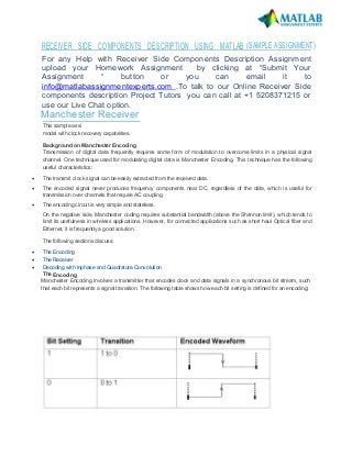
  • 1. RECEIVER SIDE COMPONENTS DESCRIPTION USING MATLAB (SAMPLE ASSIGNMENT) For any Help with Receiver Side Components Description Assignment upload your Homework Assignment by clicking at “Submit Your Assignment “ button or you can email it to info@matlabassignmentexperts.com .To talk to our Online Receiver Side components description Project Tutors you can call at +1 5208371215 or use our Live Chat option. Manchester Receiver This sample assignment shows how to use the HDL Verifier to design, test, and verify a VHDL Manchester Receiver model with clock recovery capabilities. Background on Manchester Encoding Transmission of digital data frequently requires some form of modulation to overcome limits in a physical signal channel. One technique used for modulating digital data is Manchester Encoding. This technique has the following useful characteristics:  The transmit clock signal can be easily extracted from the received data.  The encoded signal never produces frequency components near DC, regardless of the data, which is useful for transmission over channels that require AC coupling.  The encoding circuit is very simple and stateless. On the negative side, Manchester coding requires substantial bandwidth (above the Shannon limit), which tends to limit its usefulness in wireless applications. However, for connected applications such as short haul Optical fiber and Ethernet, it is frequently a good solution. The following sections discuss:  The Encoding  The Receiver  Decoding with Inphase and Quadrature Convolution The Encoding Manchester Encoding involves a transmitter that encodes clock and data signals in a synchronous bit stream, such that each bit represents a signal transition. The following table shows how each bit setting is defined for an encoding:
  • 2. Transitions in the Manchester Encoding occur at the center and beginning of each bit. The transition at the center is defined by the bit value, while the transition at the beginning is dependent on the value of the previous bit. Consider the following diagram: As the preceding Manchester encoded signals shows:  The value of 1 for the first bit forces a high-to-low transition at the center of that bit.  The value of 0 for the second bit forces a low-to-high transition at the center of that bit and, because the first bit transitioned from high-to-low, no transition occurs at the start of that bit.  The value of 0 for the third bit forces a low-to-high transition at the center of that bit and because the second bit transitioned from low-to-high, a high-to-low transition occurs at the start of that bit.  The value of 1 for the fourth bit forces a high-to-low transition at the center of that bit and, because the third bit transitioned from low-to-high, no transition occurs at the start of that bit.  The value of 0 for the fifth bit forces a low-to-high transition at the center of that bit and, because the fourth bit transitioned from high-to-low, no transition occurs at the start of that bit. The Receiver A device that receives the encoded bit stream is responsible for decoding the bit stream by separating the clock and data information. In most cases, the receiver must retrieve the original data stream by using only the encoded signal. This simplifies the communications channel, but means the receiver must overcome the following:  Differences between the clock used to encode the signal and the clock in the receiver (see the figure below).  The two clocks can be close in frequency, but small frequency errors occur.  The phase between the clocks will be arbitrary.
  • 3. The Manchester Receiver example validates the computations performed by a Manchester Receiver device that is modeled in VHDL and simulated in ModelSim. Numerous approaches are available for implementing a Manchester receiver. This example uses a Delay Lock Loop (DLL) that requires the receiver to use a clock that is very close in frequency to the transmit clock. This results in a simple clock recovery circuit that has a limited frequency lock range. The receiver over-samples the received data stream at 16 times the data rate. Thus, the receive clock must have a nominal period of 1/16th the data period. To compensate for minor differences between the transmitting and receiving clocks or drifts in the channel delay, the receiver adjusts its data period by up to one clock cycle (+/-) per data period. Thus, the receiver can use 15, 16 or 17 clock cycles to recover the data encoded from the incoming sampled signal. For example, if the receiver clock is slightly faster then the transmitter clock (frequency error), the receive cycle occasionally needs to add an extra clock cycle to compensate. Large sudden phase errors, such as those that occur at startup time, require multiple data periods to acquire a good lock on the signal. By limiting the maximum phase correction to 1/16th of the total data period, the receiver can be slow to correct large phase errors. Decoding with Inphase and Quadrature Convolution Decoding a received Manchester signal can occur in several ways, but the approach taken in this example is to consider Manchester Encoding as a digital phase modulation with two symbols: +180 and -180 degrees. By convolving the incoming signal with a reference inphase (I) and quadrature (Q) waveform at the modulation frequency, it is possible to extract the data and retrieve information about any phase errors in the received waveform. After one data cycle, the receiver computes two values (referred to as Isum and Qsum in the VHDL code), which are measurements of the I/Q convolution value. The receiver then decodes the values to predict:  The original transmitted data value for the cycle  An estimate of the phase error between the incoming signal and the receiver's data period A critical aspect of this design is the interpretation of the I/Q convolution values. At the end of a data receive cycle, the receiver translates the I/Q values into an estimate of the transmitted data and phase error. One way to present this information is to show these interpretations as plots versus measured I/Q values. Data is considered invalid if the measured I and Q are completely ambiguous about the encoded data value. In a similar way, you can generate an I/Q mapping of the phase correction value in plot format. Such a plot gives a visual representation of the decoding block. In practice, the details of this mapping have strong impact on the stability and performance of the Manchester receiver. In the ideal case where the receiver is perfectly locked to the incoming waveform, the receive cycle is 16 cycles long and the measured I/Q convolution values are fairly easy to interpret. However, data cycles that are 15 or 17 cycles
  • 4. long create some bias in the measurement of the IQ convolution. It is possible to customize the I/Q measurement during these cycles, but that would increase the size and complexity of the receiver. Instead, the data acquisition cycle is extended or shortened with no change in decoding the resulting values. However, this decoder bias can create problems with dithering or reduced noise immunity. VHDL Implementation of a Manchester Receiver The focus of this example is a VHDL implementation of a Manchester Receiver. Decoding a Manchester encoded signal presents several challenges, the most prominent of which is clock recovery. The clock is embedded in the received signal and must be extracted to reproduce the original data stream. The figure below shows the example design, which is divided into three main sections of VHDL code: IQ convolver: Samples the received signal and computes the convolution for the inphase (I) and quadrature (Q) waveforms. For each waveform, the computation is implemented as the sum of XOR operations on the sample and decoded waveform received from the state counter. Decoder: Models a combinatorial circuit that interprets the results of the I/Q convolver. State counter: Generates the I/Q waveforms that are convolved with received signals, taking into account phase errors (lags and leads), as necessary. The phase of the I/Q generator is adjusted to match the incoming Manchester encoded waveform. To accomplish the necessary adjustment, at the beginning of a new cycle, the state counter checks an adjustment value, adj, and then changes the period of the next I/Q cycle. This adjustment value is limited to adding or removing a single clock period from the 16 periods that are nominally used for an I/Q waveform. The following timing diagram shows an inphase waveform, quadrature waveform, and the convolved results with no phase error, data lags, and data leads.
  • 5. MATLAB Models of VHDL Components The example includes three MATLAB functions that test the VHDL model. A MATLAB function maps to each of the three VHDL components: I/Q convolver: Verifies that the VHDL I/Q convolver code computes expected output for a randomly generated stream of samples. The MATLAB function verifies this by computing the convolution for the inphase and quadrature waveforms (I_wf and Q_wf). The computation is implemented as an XOR and accumulation of the binary signals. Decoder: Displays a plot of the I/Q mapping generated by the decoder for visual verification. State counter: Generates the inphase and quadrature waveforms. During test benching, this MATLAB function has complete control of signals applied during the simulation, including clock generation, resets, and so on. Running the Example Starting the MATLAB Server
  • 6. The example starts the MATLAB server, hdldaemon, such that it uses TCP socket communication with a socket port number identified as available by the operating system. hdldaemon('socket',0) % Activate MATLAB server to accept foreign VHDL calls HDLDaemon socket server is running on port 4040 with 0 connections The example then calls hdldaemon with the 'status' option to get the assigned port number and store it in portnum for future reference. dstat = hdldaemon('status'); portnum = dstat.ipc_id; HDLDaemon socket server is running on port 4040 with 0 connections Both the server and client parts of an application link must use the same port number. Thus, at some point, the example program needs to forward the portnum over to ModelSim. Testing the Decoder The first component of the Manchester Receiver model to be tested is the decoder. The script creates 2 plots of the transfer function of this entity. This test is simply a visualization of the decoder behavior. The example script: 1. Sets a testisdone flag to 0 and displays informational messages. global testisdone; testisdone = 0; 2. Sets the project directory to a directory that has write access and is suitable for holding a ModelSim project. projectdir = pwd; 3. Changes the format of the project directory and decoder VHDL file specifications to the UNIX format, which ModelSim and Tcl use, by replacing backslashes () with forward slashes (/). unixprojectdir = ['"' strrep(projectdir,'','/') '"']; unixsrcfile = ['"' ... strrep(fullfile(matlabroot,'toolbox','edalink','extensions','modelsim',... 'modelsimdemos','vhdl','manchester','decoder.vhd'),'','/') ... '"']; 4. Defines a sequence of Tcl commands to be executed in the context of ModelSim. tclcmd = { ['cd ' unixprojectdir ],... 'vlib work',... ['vcom -performdefaultbinding ' unixsrcfile],... 'vsimmatlab work.decoder',... ['matlabtb decoder -mfunc manchester_decoder -socket ',num2str(portnum)],... 'run 3000',... 'quit -f'}; The previous list defines each command:  Changes to the writable project directory.
  • 7.  Adjusts the placement of the ModelSim window so it does not obscure the MATLAB window.  Creates the project library work if it does not already exist.  Compiles the VHDL file. The example script specifies the 'performdefaultbinding' option to enable default bindings in the event that they have been disabled in the modelsim.ini file.  Loads an instance of the VHDL entity decoder for MATLAB test benching with the vsimmatlab command. This command is an HDL Verifier extension to the ModelSim command set.  Initiates a MATLAB test benching session for the loaded instance of entity decoder with the matlabtb command. This command is an extension to the ModelSim command set. The command in the example specifies the entity instance, the MATLAB function that is to test the entity (manchester_decoder.m), and TCP socket communication with socket port portnum. For a link to be established between ModelSim and MATLAB, the value of portnum must match the socket port that was specified when the MATLAB server (hdldaemon) was started.  Runs the ModelSim simulation for 3000 iterations of the current resolution limit. By default, the simulation runs for 3000 nanoseconds. Quits ModelSim without asking for confirmation. 5. Starts ModelSim for use with the HDL Verifier with a call to vsim. vsim('startupfile','decoder.do','tclstart',tclcmd); This command starts ModelSim with a Tcl command script that executes some general-purpose startup commands and then the user-defined commands specified with the 'tclstart' property. The 'startfile' property causes vsim to write the entire startup Tcl command script to decoder.do for future reference or use. 6. Displays informational messages and waits for (manchester_decoder.m) to run to completion. disp('Waiting for testing of ''decoder.vhd'' to complete'); disp('(flag from manchester_decoder.m indicates completion)'); while testisdone == 0, pause(0.501); end disp('MATLAB test of decoder.vhd is complete!'); disp('Check the generated plot for results.'); Waiting for testing of 'decoder.vhd' to complete (flag from manchester_decoder.m indicates completion) done MATLAB test of decoder.vhd is complete! Check the generated plot for results.
  • 8. Testing the I/Q Convolver Similarly for the I/Q convolver. The example script: 1. Sets a testisdone flag to 0 and displays informational messages. testisdone = 0; 2. Sets the project directory to a directory that has write access and is suitable for holding a ModelSim project. projectdir = pwd; 3. Changes the format of the project directory and decoder VHDL file specifications to the UNIX format, which ModelSim and Tcl use, by replacing backslashes () with forward slashes (/). unixprojectdir = ['"' strrep(projectdir,'','/') '"']; unixsrcfile = ['"' ... strrep(fullfile(matlabroot,'toolbox','edalink','extensions','modelsim',... 'modelsimdemos','vhdl','manchester','iqconv.vhd'),'','/') ... '"']; 4. Defines a sequence of Tcl commands to be executed in the context of ModelSim. tclcmd = { ['cd ' unixprojectdir ],... 'vlib work',... ['vcom -performdefaultbinding ' unixsrcfile],...
  • 9. 'vsimmatlab work.iqconv',... 'force /iqconv/clk 1 0, 0 5 ns -repeat 10 ns ',... 'force /iqconv/enable 1',... 'force /iqconv/reset 1',... 'run 100',... ['matlabtb iqconv -rising /iqconv/clk -mfunc manchester_iqconv -socket ',num2str(portnum)],... 'run 1000',... 'quit -f'}; The following list defines each command:  Changes to the writable project directory.  Adjusts the placement of the ModelSim window so it does not obscure the MATLAB window.  Creates the project library work if it does not already exist.  Compiles the VHDL file. The example script specifies the -performdefaultbinding option to enable default bindings in the event that they have been disabled in the modelsim.ini file.  Loads an instance of the VHDL entity iqconv for MATLAB test benching with the vsimmatlab command. This command is an HDL Verifier extension to the ModelSim command set.  Applies the ModelSim force command to drive the entity's clk, enable, and reset signals, which get passed on to the test bench as oport data. The first force command specifies that clk is to be set to 1 at time equals 0, to 0 after 5 nanoseconds, and repeat the high-to-low cycle every 10 nanoseconds. The second and third force commands set the enable and reset signals to 1.  Runs the ModelSim simulation for 100 iterations of the current limit. By default, the simulation runs for 100 nanoseconds. This accounts for the startup phase.  Initiates a MATLAB test benching session for the loaded instance of entity iqconv with the matlabtb command. This command is an extension to the ModelSim command set. The command in the example specifies the entity instance iqconv, the event that triggers an invocation of the MATLAB function, the MATLAB function that is to test the entity (manchester_iqconv.m), and TCP socket communication with socket port portnum. The -rising option specifies that the MATLAB function be called when clk experiences a rising edge. For a link to be established between ModelSim and MATLAB, the value specified with -socket must match the socket port that was specified when the MATLAB server (hdldaemon) was started.  Runs the ModelSim simulation for 1000 iterations of the current resolution limit. By default, the simulation runs for 1000 nanoseconds.  Quits ModelSim without asking for confirmation. 5. Starts ModelSim for use with the HDL Verifier with a call to vsim. vsim('startupfile','iqconv.do','tclstart',tclcmd); This command starts ModelSim with a Tcl command script that executes some general-purpose startup commands and then the user-defined commands specified with the 'tclstart' property. The 'startfile' property causes vsim to write the entire startup Tcl command script to iqconv.do for future reference or use. 6. Displays informational messages and waits for (manchester_iqconv.m) to run to completion. disp('Waiting for testing of ''iqconv.vhd'' to complete'); disp('(flag from manchester_iqconv.m indicates completion)'); while testisdone == 0, pause(0.501); end
  • 10. disp('Test of iqconv.vhd complete (If it failed, there would be an error message printed above)!'); Waiting for testing of 'iqconv.vhd' to complete (flag from manchester_iqconv.m indicates completion) Test of iqconv.vhd complete (If it failed, there would be an error message printed above)! Testing the State Counter Now we test the State Counter (statecnt.vhd). The script will create checks isum and qsum outputs for a randomly generated stream of data samples and sets the testisdone flag to 0 and displays informational messages. testisdone = 0; projectdir = pwd; unixprojectdir = ['"' strrep(projectdir,'','/') '"']; unixsrcfile = ['"' ... strrep(fullfile(matlabroot,'toolbox','edalink','extensions','modelsim','modelsimdemos',... 'vhdl','manchester','statecnt.vhd'),'','/') ... '"']; tclcmd = { ['cd ' unixprojectdir ],... 'vlib work',... ['vcom -performdefaultbinding ' unixsrcfile],... 'vsimmatlab -t 1ns work.statecnt ',... 'force /statecnt/clk 1 0, 0 5 ns -repeat 10 ns ',... ['matlabtb statecnt -mfunc manchester_statecnt -socket ',num2str(portnum)],... 'run 30000',... 'quit -f'}; The following list defines each TCL command in the tclcmd:  Changes to the writable project directory.  Adjusts the placement of the ModelSim window so it does not obscure the MATLAB window.  Creates the project library work if it does not already exist.  Compiles the VHDL file. The example script specifies the -performdefaultbinding option to enable default bindings in the event that they have been disabled in the modelsim.ini file. Loads an instance of the VHDL entity statecnt for MATLAB test benching with the vsimmatlab command. This command is an HDL Verifier extension to the ModelSim command set. The -t option specifies a ModelSim simulator time resolution of 1 nanosecond (the default). Applies the ModelSim force command to drive the entity's clk signal, which gets passed on to the test bench as oport data. The force command specifies that clk is to be set to 1 at time equals 0, to 0 after 5 nanoseconds, and repeat the high-to- low cycle every 10 nanoseconds.  Initiates a MATLAB test benching session for the loaded instance of entity statecnt with the matlabtb command. This command is an extension to the ModelSim command set. The command in the example specifies the entity instance statecnt, the MATLAB function that is to test the entity ( manchester_statecnt.m), and TCP socket communication with socket port portnum. For a link to be established between ModelSim and MATLAB, the value specified with - socket must match the socket port that was specified when the MATLAB server (hdldaemon) was started.  Runs the ModelSim simulation for 30000 iterations of the current resolution limit. By default, the simulation runs for 30000 nanoseconds.  Quits ModelSim without asking for confirmation.
  • 11. vsim('startupfile','statecnt.do','tclstart',tclcmd); disp('Waiting for testing of ''statecnt.vhd'' to complete'); disp('(flag from manchester_statecnt.m indicates completion)'); while testisdone == 0, pause(0.501); end disp('MATLAB test of statecnt.vhd is complete!'); disp('Check the generated plot for results.'); Waiting for testing of 'statecnt.vhd' to complete (flag from manchester_statecnt.m indicates completion) MATLAB test of statecnt.vhd is complete! Check the generated plot for results. Kill hdldaemon hdldaemon('KILL'); HDLDaemon server was shutdown Test of statecnt.vhd complete (Examine plot produced). This concludes the manchester tutorial example.