SlideShare ist ein Scribd-Unternehmen logo
1 von 5
Collector pipes in siphonic roof drainage systems: to
                         incline or not?
                                      Marc Buitenhuis

    Hydraulic research engineer Akatherm International BV, Panningen, The Netherlands

                                          10-09-2008

Abstract

Some install horizontal collector pipes of siphonic roof drainage systems under a fall angle or
inclination. This is however causing a delay in the priming of the system and thus is not only
unnecessary but even disadvantageous. The hydraulic jump that has to form to close the inner
periphery of the pipe and make it work syphonic is less pronounced when the collector pipe
has an inclination.


   1. Introduction                                 of the hydraulic jump depends on 2
                                                   parameters:
Some install collector pipes of syphonic               1. the velocity of the flow streaming
roof drainage systems under inclination                    into the horizontal pipe
thinking that the water will then be                   2. the resistance of the pipe beyond
transported easier through the pipe system.                the entrance of the collector pipe.
This however is not the case in syphonic
roof drainage systems as will be explained
in this article. It will even delay the
priming of the system and thus work
disadvantageous.

   2. Principle of syphonic roof
      drainage
                                                   Figure 1. Forming of the hydraulic jump at start up of siphonic
                                                   roof drainage system
The working principle of syphonic roof
drainage is the full bore flow of the system.      The principle can be compared to the
At full bore flow the water column closing         stream of vehicles on highways or race
off the pipe diameter will generate a              tracks. Vehicles can accelerate optimally
suction pressure dragging the water from           on roads that are straight and keep on
the roof in its wake. One thus has to obtain       being straight for miles. As soon as there is
and maintain a full bore flow for optimal          a curve in the road the vehicles have to
functioning of the system.                         slow down. When the first vehicle
The full bore flow is initiated by the             decelerates the one behind him has to
hydraulic jump (see figure 1) at the               decelerate also and the distance between
entrance of the horizontal part of tail pipe       the vehicles decreases. This is very often
or collector pipe of the system. The shape
the moment for accidents to happen: there
is an increasing chance for collision.            For incompressible inviscid flow they
Exactly this is the case for fluid particles in   become:
                                                        
a stream. When particles are redirected               DV    
                                                  ρ      = ρg − ∇p
from the vertical downfall to horizontal              Dt
flow the fluid is decelerated. As fluid           and are known in this form as Euler’s
particles have no brakes they will collide        equations.
and the only way they can go is up,                                                       p
creating height and thus a hydraulic jump.        The headloss ΔH is defined as ΔH = ρ . g
The above explains 2 things: first of all         Substituting this in the above Euler’s
why an increasing length of vertical tail         equations and dividing by ρ gives:
pipe leads to earlier priming, secondly why          
                                                  DV   
an increasing resistance in the collector            = g − g∇H
                                                  Dt
pipe leads to this same result.                   In streamline coordinates along the x-axis
An increasing length of tail pipe gives           and taking the z-direction the direction of
more time for acceleration of the water           gravity:
coming from the roof, thus to higher                 
                                                  DV      ∂Vx      ∂Vx
velocities at the bend to the horizontal                =      +Vx     = −g∇ − g∇ =
                                                                            z    H
                                                  Dt       ∂t       ∂x
pipe. This will lead to a higher hydraulic
                                                                  ∂H
jump when the flow is decelerated in the          − g ⋅ sin β − g
horizontal pipe.                                                  ∂x
Also the more the flow is decelerated in          With a constant diameter of the pipe and
the horizontal pipe, thus the higher the          thus constant cross section, A, this can be
resistance downstream of the bend, the            further rewritten to:
                                                      
higher the hydraulic jump will be.                DQ ∂Q Q ∂Q
                                                       =       +         = −A ⋅ g∇z − A ⋅ g∇H =
The higher the hydraulic jump will be the         Dt       ∂t    A ∂x
earlier the full pipe diameter will be closed                             ∂H
                                                  − A ⋅ g ⋅ sin β − A ⋅ g
off by water and priming will start.                                      ∂x
When the horizontal pipe is (slightly)
inclined the water will run off easier and        with β the angle between the horizontal
thus the hydraulic jump will be less              streamline x and the direction
pronounced, delaying the onset to priming         perpendicular to the gravity (β positive
of the system.                                    when the streamline ascends).

    3. Theoretical background

In this section the theoretical background
for the phenomenon described above will
be derived.                                                Q
In fluid dynamics the Navier-Stokes
                                                                            x
equations are the general form of the
momentum equations that account for fluid                                           -β
motion and are written as:
                                                                  g
 D ( ρV )                     
          = ρg − ∇p + µ∇2V
   Dt
                                                  For a descending collector pipe the angle β
where ρ is the density,                           thus is negative, the term with this
        V is the velocity                         parameter thus positive, driving the speed
p is the pressure,                                in the collector pipe up and thus making it
μ is the viscosity                                decelerate less, producing a less
pronounced hydraulic jump and thus
delaying priming (full bore flow) in the                         4. Conclusions
system.
                                                             In this article it has been illustrated that
In a steady incompressible, inviscid, full                   other then for conventional roof drainage
bore flow integration of Euler’s equations                   systems an inclination of the collector pipe
over a streamline gives the well known                       in a siphonic roof drainage system is not
Bernoulli equation:                                          advantageous and will delay the priming of
p            V2                                              the system. Thus it is advised to install the
    + gz +      = const
ρ            2                                               collector pipes horizontally for proper
This equation is often referred to to easily                 siphonic functioning.
explain the principle of siphonic roof
drainage.
    5. References

    1.   Fox, Robert W., McDonald, Alan T. Introduction to fluid mechanics, third edition, 1985, School of
         Mechanical Engineering Purdue University, John Wiley & Sons
    2.   Scott Arthur, John A. Swaffield, Siphonic roof drainage: current understanding, 2001, Water research
         group, Department of civil and offshore engineering, Heriot-Watt University, Edinburg, Scotland (UK)
    3.   G.B. Wright, S. Arthur, J.A. Swaffield, Numerical simulation of the dynamic operation of multi-outlet
         siphonic roof drainage systems, 2005, Drainage and water supply research group, School of the build
         environment, Heriot-Watt University, Edinburg, Scotland (UK)
    4.   Scott Arthur, The priming focused design of siphonic roof drainage, drain
    5.   age research group, School of the built environment, Heriot-Watt University, Edinburg, Scotland (UK)
    6.   S. Arthur, G.B. Wright, Siphonic roof drainage systems – priming focused design, 2006, School of the
         built environment, Heriot-Watt University, Edinburg, Scotland (UK)
    7.   S. Arthur, J.A. Swaffield, Siphonic roof drainage system analysis utilizing unsteady flow theory, 2000,
         Department of building engineering and surveying, Heriot-Watt University, Edinburg, Scotland (UK)

Weitere ähnliche Inhalte

Was ist angesagt?

Characteristics of sharp weirs and the hydraulic jump
Characteristics of sharp weirs and the hydraulic jumpCharacteristics of sharp weirs and the hydraulic jump
Characteristics of sharp weirs and the hydraulic jump
Dickens Mimisa
 
Water hammer in pipe_AMIT
Water hammer in pipe_AMITWater hammer in pipe_AMIT
Water hammer in pipe_AMIT
Amit Sharma
 

Was ist angesagt? (20)

Chapter 5 drop sturcutures
Chapter 5 drop sturcuturesChapter 5 drop sturcutures
Chapter 5 drop sturcutures
 
Presentation on flow through simple pipes and flow through compound pipe
Presentation on flow through simple pipes and flow through compound pipePresentation on flow through simple pipes and flow through compound pipe
Presentation on flow through simple pipes and flow through compound pipe
 
Fluid dynamics
Fluid dynamicsFluid dynamics
Fluid dynamics
 
Weirs and flumes with broad
Weirs and flumes  with broad Weirs and flumes  with broad
Weirs and flumes with broad
 
Weirs
WeirsWeirs
Weirs
 
flow through pipe
flow through pipeflow through pipe
flow through pipe
 
Hydraulics of structures
Hydraulics of structuresHydraulics of structures
Hydraulics of structures
 
Flow through pipe
Flow through pipeFlow through pipe
Flow through pipe
 
Pipe sizing
Pipe sizingPipe sizing
Pipe sizing
 
Rapidly varied flow
Rapidly varied flowRapidly varied flow
Rapidly varied flow
 
Canal drop notch type -design steps
Canal drop notch type -design stepsCanal drop notch type -design steps
Canal drop notch type -design steps
 
Characteristics of sharp weirs and the hydraulic jump
Characteristics of sharp weirs and the hydraulic jumpCharacteristics of sharp weirs and the hydraulic jump
Characteristics of sharp weirs and the hydraulic jump
 
(Part iii)- open channels
(Part iii)- open channels(Part iii)- open channels
(Part iii)- open channels
 
Module 4
Module 4Module 4
Module 4
 
Open Channel VS Pipe Flow
Open Channel VS Pipe FlowOpen Channel VS Pipe Flow
Open Channel VS Pipe Flow
 
160120119032 2141906
160120119032 2141906160120119032 2141906
160120119032 2141906
 
Flow Through Pipes - Hydraulics
Flow Through Pipes - HydraulicsFlow Through Pipes - Hydraulics
Flow Through Pipes - Hydraulics
 
economic channel section
economic channel sectioneconomic channel section
economic channel section
 
Open channelhydraulics2
Open channelhydraulics2Open channelhydraulics2
Open channelhydraulics2
 
Water hammer in pipe_AMIT
Water hammer in pipe_AMITWater hammer in pipe_AMIT
Water hammer in pipe_AMIT
 

Andere mochten auch

13 decomposição de um número em fatores primos
13 decomposição de um número em fatores primos13 decomposição de um número em fatores primos
13 decomposição de um número em fatores primos
Carla Gomes
 
Eclipse 10 years Party
Eclipse 10 years PartyEclipse 10 years Party
Eclipse 10 years Party
Mite Mitreski
 
Soil experiment by the Pinakazoidz
Soil experiment by the PinakazoidzSoil experiment by the Pinakazoidz
Soil experiment by the Pinakazoidz
newham5-6
 
Arquivo 2004 de a a z
Arquivo 2004 de a a zArquivo 2004 de a a z
Arquivo 2004 de a a z
cepmaio
 
Atividades juninas
Atividades juninas Atividades juninas
Atividades juninas
cepmaio
 
Motivation
MotivationMotivation
Motivation
yzhu6
 
L presentation
L presentationL presentation
L presentation
j2chris
 
421 672 Management Of Technological Enterprises (2008 Lecture 2)
421 672 Management Of Technological Enterprises (2008   Lecture 2)421 672 Management Of Technological Enterprises (2008   Lecture 2)
421 672 Management Of Technological Enterprises (2008 Lecture 2)
William Hall
 
Curso de idiomas globo inglês livro003
Curso de idiomas globo inglês livro003Curso de idiomas globo inglês livro003
Curso de idiomas globo inglês livro003
rosemere12
 

Andere mochten auch (20)

Power Living Program
Power  Living  ProgramPower  Living  Program
Power Living Program
 
Ceará
CearáCeará
Ceará
 
13 decomposição de um número em fatores primos
13 decomposição de um número em fatores primos13 decomposição de um número em fatores primos
13 decomposição de um número em fatores primos
 
How Does the inclusion of interactive virtual games influence rehabilitation ...
How Does the inclusion of interactive virtual games influence rehabilitation ...How Does the inclusion of interactive virtual games influence rehabilitation ...
How Does the inclusion of interactive virtual games influence rehabilitation ...
 
Eclipse 10 years Party
Eclipse 10 years PartyEclipse 10 years Party
Eclipse 10 years Party
 
Leerkrassistent Pennenstreken
Leerkrassistent PennenstrekenLeerkrassistent Pennenstreken
Leerkrassistent Pennenstreken
 
Keynote Mobile
Keynote MobileKeynote Mobile
Keynote Mobile
 
Soil experiment by the Pinakazoidz
Soil experiment by the PinakazoidzSoil experiment by the Pinakazoidz
Soil experiment by the Pinakazoidz
 
Arquivo 2004 de a a z
Arquivo 2004 de a a zArquivo 2004 de a a z
Arquivo 2004 de a a z
 
Atividades juninas
Atividades juninas Atividades juninas
Atividades juninas
 
Motivation
MotivationMotivation
Motivation
 
L presentation
L presentationL presentation
L presentation
 
Automatic enrolment
Automatic enrolmentAutomatic enrolment
Automatic enrolment
 
Virtual Networking and Hospitality
Virtual Networking and HospitalityVirtual Networking and Hospitality
Virtual Networking and Hospitality
 
421 672 Management Of Technological Enterprises (2008 Lecture 2)
421 672 Management Of Technological Enterprises (2008   Lecture 2)421 672 Management Of Technological Enterprises (2008   Lecture 2)
421 672 Management Of Technological Enterprises (2008 Lecture 2)
 
Sites Making the List the First Time
Sites Making the List the First TimeSites Making the List the First Time
Sites Making the List the First Time
 
The holocaust
The holocaustThe holocaust
The holocaust
 
Apuntes y aproximaciones culturales
Apuntes y aproximaciones culturalesApuntes y aproximaciones culturales
Apuntes y aproximaciones culturales
 
Curso de idiomas globo inglês livro003
Curso de idiomas globo inglês livro003Curso de idiomas globo inglês livro003
Curso de idiomas globo inglês livro003
 
Class 7.ss
Class 7.ssClass 7.ss
Class 7.ss
 

Ähnlich wie Tp1 collector pipes in siphonic roof drainage systems to incline or not to incline(dr)

Tp2 siphonic roof drainage systems the road to priming(dr)
Tp2 siphonic roof drainage systems the road to priming(dr)Tp2 siphonic roof drainage systems the road to priming(dr)
Tp2 siphonic roof drainage systems the road to priming(dr)
Marc Buitenhuis
 
FYP Presentation v2.0
FYP Presentation v2.0FYP Presentation v2.0
FYP Presentation v2.0
Bianchi Dy
 
Fluid+flow
Fluid+flowFluid+flow
Fluid+flow
MidoOoz
 
Flow through nozzel_AMIT
Flow through nozzel_AMITFlow through nozzel_AMIT
Flow through nozzel_AMIT
Amit Sharma
 
FLUID-MECHANICS-AND-MASS-TRANSFAR-FM7.pdf
FLUID-MECHANICS-AND-MASS-TRANSFAR-FM7.pdfFLUID-MECHANICS-AND-MASS-TRANSFAR-FM7.pdf
FLUID-MECHANICS-AND-MASS-TRANSFAR-FM7.pdf
rohitkumar00486
 

Ähnlich wie Tp1 collector pipes in siphonic roof drainage systems to incline or not to incline(dr) (20)

Tp2 siphonic roof drainage systems the road to priming(dr)
Tp2 siphonic roof drainage systems the road to priming(dr)Tp2 siphonic roof drainage systems the road to priming(dr)
Tp2 siphonic roof drainage systems the road to priming(dr)
 
Fluid Mechanics Unit-2 (vk-ssm)
Fluid Mechanics Unit-2  (vk-ssm)Fluid Mechanics Unit-2  (vk-ssm)
Fluid Mechanics Unit-2 (vk-ssm)
 
FYP Presentation v2.0
FYP Presentation v2.0FYP Presentation v2.0
FYP Presentation v2.0
 
Ch#1 ADVANCED OPEN CHANNEL HYDRAULICS.pdf
Ch#1 ADVANCED OPEN CHANNEL HYDRAULICS.pdfCh#1 ADVANCED OPEN CHANNEL HYDRAULICS.pdf
Ch#1 ADVANCED OPEN CHANNEL HYDRAULICS.pdf
 
Fluid+flow
Fluid+flowFluid+flow
Fluid+flow
 
Flow through nozzel_AMIT
Flow through nozzel_AMITFlow through nozzel_AMIT
Flow through nozzel_AMIT
 
CH7 PC and SR.pptx
CH7 PC and SR.pptxCH7 PC and SR.pptx
CH7 PC and SR.pptx
 
6. Flow Through uc Channels (CE).pdf
6. Flow Through uc Channels (CE).pdf6. Flow Through uc Channels (CE).pdf
6. Flow Through uc Channels (CE).pdf
 
FM-II Lec 4
FM-II Lec 4FM-II Lec 4
FM-II Lec 4
 
Flow through pipes
Flow through pipesFlow through pipes
Flow through pipes
 
Ch 3.pdf
Ch 3.pdfCh 3.pdf
Ch 3.pdf
 
Losses in Pipe
Losses in PipeLosses in Pipe
Losses in Pipe
 
Chapter 5 Fetter Ground water flow to wells
Chapter 5 Fetter Ground water flow to wellsChapter 5 Fetter Ground water flow to wells
Chapter 5 Fetter Ground water flow to wells
 
Modeling of transient fluid flow in the simple pipeline system
Modeling of transient fluid flow in the simple pipeline systemModeling of transient fluid flow in the simple pipeline system
Modeling of transient fluid flow in the simple pipeline system
 
CHAPTER NO 2
CHAPTER NO 2 CHAPTER NO 2
CHAPTER NO 2
 
Hydroelectric power plants (chapter 5)
Hydroelectric power plants   (chapter 5)Hydroelectric power plants   (chapter 5)
Hydroelectric power plants (chapter 5)
 
9-Viscous flow in ducts.pptx
9-Viscous flow in ducts.pptx9-Viscous flow in ducts.pptx
9-Viscous flow in ducts.pptx
 
FLUID-MECHANICS-AND-MASS-TRANSFAR-FM7.pdf
FLUID-MECHANICS-AND-MASS-TRANSFAR-FM7.pdfFLUID-MECHANICS-AND-MASS-TRANSFAR-FM7.pdf
FLUID-MECHANICS-AND-MASS-TRANSFAR-FM7.pdf
 
Ground water flow to wells
Ground water flow to wellsGround water flow to wells
Ground water flow to wells
 
Chapter 1bbj.pptx
Chapter 1bbj.pptxChapter 1bbj.pptx
Chapter 1bbj.pptx
 

Mehr von Marc Buitenhuis

Flow phenomena of a siphonic roof outlet anqip format
Flow phenomena of a siphonic roof outlet anqip formatFlow phenomena of a siphonic roof outlet anqip format
Flow phenomena of a siphonic roof outlet anqip format
Marc Buitenhuis
 
Tp7 akavent systems principles(dr)
Tp7 akavent systems principles(dr)Tp7 akavent systems principles(dr)
Tp7 akavent systems principles(dr)
Marc Buitenhuis
 
Tp5 nothing but the rain(dr)
Tp5 nothing but the rain(dr)Tp5 nothing but the rain(dr)
Tp5 nothing but the rain(dr)
Marc Buitenhuis
 
Tp3 siphonic roof drainage systems gutters(dr)
Tp3 siphonic roof drainage systems gutters(dr)Tp3 siphonic roof drainage systems gutters(dr)
Tp3 siphonic roof drainage systems gutters(dr)
Marc Buitenhuis
 
Tp4 siphonic roof drainage systemsno space to breath(dr)
Tp4 siphonic roof drainage systemsno space to breath(dr)Tp4 siphonic roof drainage systemsno space to breath(dr)
Tp4 siphonic roof drainage systemsno space to breath(dr)
Marc Buitenhuis
 

Mehr von Marc Buitenhuis (7)

Enduria2a
Enduria2aEnduria2a
Enduria2a
 
Enduria
EnduriaEnduria
Enduria
 
Flow phenomena of a siphonic roof outlet anqip format
Flow phenomena of a siphonic roof outlet anqip formatFlow phenomena of a siphonic roof outlet anqip format
Flow phenomena of a siphonic roof outlet anqip format
 
Tp7 akavent systems principles(dr)
Tp7 akavent systems principles(dr)Tp7 akavent systems principles(dr)
Tp7 akavent systems principles(dr)
 
Tp5 nothing but the rain(dr)
Tp5 nothing but the rain(dr)Tp5 nothing but the rain(dr)
Tp5 nothing but the rain(dr)
 
Tp3 siphonic roof drainage systems gutters(dr)
Tp3 siphonic roof drainage systems gutters(dr)Tp3 siphonic roof drainage systems gutters(dr)
Tp3 siphonic roof drainage systems gutters(dr)
 
Tp4 siphonic roof drainage systemsno space to breath(dr)
Tp4 siphonic roof drainage systemsno space to breath(dr)Tp4 siphonic roof drainage systemsno space to breath(dr)
Tp4 siphonic roof drainage systemsno space to breath(dr)
 

Tp1 collector pipes in siphonic roof drainage systems to incline or not to incline(dr)

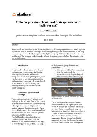
  • 1. Collector pipes in siphonic roof drainage systems: to incline or not? Marc Buitenhuis Hydraulic research engineer Akatherm International BV, Panningen, The Netherlands 10-09-2008 Abstract Some install horizontal collector pipes of siphonic roof drainage systems under a fall angle or inclination. This is however causing a delay in the priming of the system and thus is not only unnecessary but even disadvantageous. The hydraulic jump that has to form to close the inner periphery of the pipe and make it work syphonic is less pronounced when the collector pipe has an inclination. 1. Introduction of the hydraulic jump depends on 2 parameters: Some install collector pipes of syphonic 1. the velocity of the flow streaming roof drainage systems under inclination into the horizontal pipe thinking that the water will then be 2. the resistance of the pipe beyond transported easier through the pipe system. the entrance of the collector pipe. This however is not the case in syphonic roof drainage systems as will be explained in this article. It will even delay the priming of the system and thus work disadvantageous. 2. Principle of syphonic roof drainage Figure 1. Forming of the hydraulic jump at start up of siphonic roof drainage system The working principle of syphonic roof drainage is the full bore flow of the system. The principle can be compared to the At full bore flow the water column closing stream of vehicles on highways or race off the pipe diameter will generate a tracks. Vehicles can accelerate optimally suction pressure dragging the water from on roads that are straight and keep on the roof in its wake. One thus has to obtain being straight for miles. As soon as there is and maintain a full bore flow for optimal a curve in the road the vehicles have to functioning of the system. slow down. When the first vehicle The full bore flow is initiated by the decelerates the one behind him has to hydraulic jump (see figure 1) at the decelerate also and the distance between entrance of the horizontal part of tail pipe the vehicles decreases. This is very often or collector pipe of the system. The shape
  • 2. the moment for accidents to happen: there is an increasing chance for collision. For incompressible inviscid flow they Exactly this is the case for fluid particles in become:  a stream. When particles are redirected DV  ρ = ρg − ∇p from the vertical downfall to horizontal Dt flow the fluid is decelerated. As fluid and are known in this form as Euler’s particles have no brakes they will collide equations. and the only way they can go is up, p creating height and thus a hydraulic jump. The headloss ΔH is defined as ΔH = ρ . g The above explains 2 things: first of all Substituting this in the above Euler’s why an increasing length of vertical tail equations and dividing by ρ gives: pipe leads to earlier priming, secondly why  DV  an increasing resistance in the collector = g − g∇H Dt pipe leads to this same result. In streamline coordinates along the x-axis An increasing length of tail pipe gives and taking the z-direction the direction of more time for acceleration of the water gravity: coming from the roof, thus to higher  DV ∂Vx ∂Vx velocities at the bend to the horizontal = +Vx = −g∇ − g∇ = z H Dt ∂t ∂x pipe. This will lead to a higher hydraulic ∂H jump when the flow is decelerated in the − g ⋅ sin β − g horizontal pipe. ∂x Also the more the flow is decelerated in With a constant diameter of the pipe and the horizontal pipe, thus the higher the thus constant cross section, A, this can be resistance downstream of the bend, the further rewritten to:  higher the hydraulic jump will be. DQ ∂Q Q ∂Q = + = −A ⋅ g∇z − A ⋅ g∇H = The higher the hydraulic jump will be the Dt ∂t A ∂x earlier the full pipe diameter will be closed ∂H − A ⋅ g ⋅ sin β − A ⋅ g off by water and priming will start. ∂x When the horizontal pipe is (slightly) inclined the water will run off easier and with β the angle between the horizontal thus the hydraulic jump will be less streamline x and the direction pronounced, delaying the onset to priming perpendicular to the gravity (β positive of the system. when the streamline ascends). 3. Theoretical background In this section the theoretical background for the phenomenon described above will be derived. Q In fluid dynamics the Navier-Stokes x equations are the general form of the momentum equations that account for fluid -β motion and are written as:  g D ( ρV )   = ρg − ∇p + µ∇2V Dt For a descending collector pipe the angle β where ρ is the density, thus is negative, the term with this V is the velocity parameter thus positive, driving the speed p is the pressure, in the collector pipe up and thus making it μ is the viscosity decelerate less, producing a less
  • 3. pronounced hydraulic jump and thus delaying priming (full bore flow) in the 4. Conclusions system. In this article it has been illustrated that In a steady incompressible, inviscid, full other then for conventional roof drainage bore flow integration of Euler’s equations systems an inclination of the collector pipe over a streamline gives the well known in a siphonic roof drainage system is not Bernoulli equation: advantageous and will delay the priming of p V2 the system. Thus it is advised to install the + gz + = const ρ 2 collector pipes horizontally for proper This equation is often referred to to easily siphonic functioning. explain the principle of siphonic roof drainage. 5. References 1. Fox, Robert W., McDonald, Alan T. Introduction to fluid mechanics, third edition, 1985, School of Mechanical Engineering Purdue University, John Wiley & Sons 2. Scott Arthur, John A. Swaffield, Siphonic roof drainage: current understanding, 2001, Water research group, Department of civil and offshore engineering, Heriot-Watt University, Edinburg, Scotland (UK) 3. G.B. Wright, S. Arthur, J.A. Swaffield, Numerical simulation of the dynamic operation of multi-outlet siphonic roof drainage systems, 2005, Drainage and water supply research group, School of the build environment, Heriot-Watt University, Edinburg, Scotland (UK) 4. Scott Arthur, The priming focused design of siphonic roof drainage, drain 5. age research group, School of the built environment, Heriot-Watt University, Edinburg, Scotland (UK) 6. S. Arthur, G.B. Wright, Siphonic roof drainage systems – priming focused design, 2006, School of the built environment, Heriot-Watt University, Edinburg, Scotland (UK) 7. S. Arthur, J.A. Swaffield, Siphonic roof drainage system analysis utilizing unsteady flow theory, 2000, Department of building engineering and surveying, Heriot-Watt University, Edinburg, Scotland (UK)
  • 4. pronounced hydraulic jump and thus delaying priming (full bore flow) in the 4. Conclusions system. In this article it has been illustrated that In a steady incompressible, inviscid, full other then for conventional roof drainage bore flow integration of Euler’s equations systems an inclination of the collector pipe over a streamline gives the well known in a siphonic roof drainage system is not Bernoulli equation: advantageous and will delay the priming of p V2 the system. Thus it is advised to install the + gz + = const ρ 2 collector pipes horizontally for proper This equation is often referred to to easily siphonic functioning. explain the principle of siphonic roof drainage. 5. References 1. Fox, Robert W., McDonald, Alan T. Introduction to fluid mechanics, third edition, 1985, School of Mechanical Engineering Purdue University, John Wiley & Sons 2. Scott Arthur, John A. Swaffield, Siphonic roof drainage: current understanding, 2001, Water research group, Department of civil and offshore engineering, Heriot-Watt University, Edinburg, Scotland (UK) 3. G.B. Wright, S. Arthur, J.A. Swaffield, Numerical simulation of the dynamic operation of multi-outlet siphonic roof drainage systems, 2005, Drainage and water supply research group, School of the build environment, Heriot-Watt University, Edinburg, Scotland (UK) 4. Scott Arthur, The priming focused design of siphonic roof drainage, drain 5. age research group, School of the built environment, Heriot-Watt University, Edinburg, Scotland (UK) 6. S. Arthur, G.B. Wright, Siphonic roof drainage systems – priming focused design, 2006, School of the built environment, Heriot-Watt University, Edinburg, Scotland (UK) 7. S. Arthur, J.A. Swaffield, Siphonic roof drainage system analysis utilizing unsteady flow theory, 2000, Department of building engineering and surveying, Heriot-Watt University, Edinburg, Scotland (UK)
  • 5. pronounced hydraulic jump and thus delaying priming (full bore flow) in the 4. Conclusions system. In this article it has been illustrated that In a steady incompressible, inviscid, full other then for conventional roof drainage bore flow integration of Euler’s equations systems an inclination of the collector pipe over a streamline gives the well known in a siphonic roof drainage system is not Bernoulli equation: advantageous and will delay the priming of p V2 the system. Thus it is advised to install the + gz + = const ρ 2 collector pipes horizontally for proper This equation is often referred to to easily siphonic functioning. explain the principle of siphonic roof drainage. 5. References 1. Fox, Robert W., McDonald, Alan T. Introduction to fluid mechanics, third edition, 1985, School of Mechanical Engineering Purdue University, John Wiley & Sons 2. Scott Arthur, John A. Swaffield, Siphonic roof drainage: current understanding, 2001, Water research group, Department of civil and offshore engineering, Heriot-Watt University, Edinburg, Scotland (UK) 3. G.B. Wright, S. Arthur, J.A. Swaffield, Numerical simulation of the dynamic operation of multi-outlet siphonic roof drainage systems, 2005, Drainage and water supply research group, School of the build environment, Heriot-Watt University, Edinburg, Scotland (UK) 4. Scott Arthur, The priming focused design of siphonic roof drainage, drain 5. age research group, School of the built environment, Heriot-Watt University, Edinburg, Scotland (UK) 6. S. Arthur, G.B. Wright, Siphonic roof drainage systems – priming focused design, 2006, School of the built environment, Heriot-Watt University, Edinburg, Scotland (UK) 7. S. Arthur, J.A. Swaffield, Siphonic roof drainage system analysis utilizing unsteady flow theory, 2000, Department of building engineering and surveying, Heriot-Watt University, Edinburg, Scotland (UK)