
Empfohlen
Empfohlen
Weitere ähnliche Inhalte
Andere mochten auch
Ähnlich wie 75959914 vcads-user-manual-volvo
Ähnlich wie 75959914 vcads-user-manual-volvo (20)
Kürzlich hochgeladen
Kürzlich hochgeladen (20)
75959914 vcads-user-manual-volvo
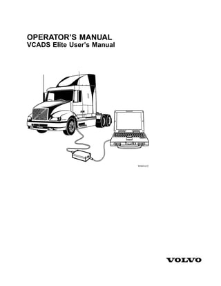
- 1. OPERATOR’S MANUAL VCADS Elite User’s Manual W0001632
- 3. Contents General .................................................. 1 Welcome to VCADS Elite .................... 1 Specifications .......................................... 4 PC/System Requirements ...................... 4 Tools ........................................................ 6 Special Tools ......................................... 6 Design and Function ............................. 7 PC Setup ................................................ 7 VCADS Elite Installation ................... 12 Initial Start-Up of VCADS Elite ........ 14 User ID and Password ........................ 17 Operations- General Information ........ 32 ECU Designations ............................... 33 Updates ................................................. 44 General ................................................ 44 CD Updates ......................................... 44 Network Updates ................................. 45 Troubleshooting .................................... 48 VCADS Elite Troubleshooting ........... 48 Windows, Basics ................................... 50 Windows, Basics .................................... 50
- 5. General 1 Welcome to VCADS Elite W0001632 Many functions in today’s modern vehicles are con- trolled by electronic control units (ECUs). ECUs control components such as the engine, instrumentation and cer- tain vehicle functions. VCADS Elite is a Windows TM - based software tool de- veloped to test, calibrate and program parameters on Volvo ECUs. VCADS Elite software is installed on a PC. The PC is connected to the communication connector in the vehicle via the communication interface (Volvo part number 9998555). VCADS Elite provides tests and calibrations for Volvo vehicles that are equipped with the Vehicle Electronics ’98 (VECTRO II) or VERSION2 electronic control sys- tems. The application consists of a number of standard graphical interfaces, such as graphs and continuous dis- plays of parameter values. The operations are organized in the menu according to function groups. Some ECUs have changeable parameters that can be used to adjust or customize certain functions. Volvo ECUs often have two types of parameters: Customer parameters and Vehicle parameters.
- 6. 2 General Customer parameters can be programmed locally using VCADS Elite. Vehicle parameters generally are used to configure the vehicle when it is built and alteration of these parameters requires a connection to VDA (Vehicle Data Administration) at Volvo. These parameters cannot be read or programmed with VCADS Elite. These changes must be performed by a Volvo Truck dealer. VCADS Elite is based on an application called VCADS Pro. This is why the name “VCADS Pro” is seen in many places throughout the application. VCADS Pro is used globally by Volvo dealers to support a wide range of Volvo products. This manual is intended to guide the user through the set up and installation of VCADS Elite. Some operations are explained in this manual, however, for more information refer to the user’s manual that is provided in the application. The manual within the appli- cation contains information that may or may not apply to VCADS Elite. To access the manual, see “Help Text” page 43. Keyboard Conventions This section describes a number of keyboard conventions that are used in this Service Information. • Keys are shown in bold uppercase letters: “ALT”. • Combinations of keys appear with a + sign between the corresponding keys. ALT+F4 means press ALT first, then F4 and then release both keys. • Text to be entered by the user is shown in bold type. • Buttons on the screen appear in bold type: “OK”. • Window names, menus and menu functions appear in bold type: “Open...”. • Numbers in parentheses “(1)” refer to call-outs in an adjacent illustration.
- 7. General 3 Helpdesk NOTE! Read the User’s guide for the PC and this intro- ductory manual before using the VCADS Elite tool. In the event of problems with the VCADS Elite software, please contact the Volvo Helpdesk at 800–888–2039. Choose the option for Service Functions, then Technical Service Support. When asked to choose a function group, press 3. Choose the option for VCADS Pro Questions. User ID Each VCADS Elite user has a personal user ID and password. The user ID is assigned by Volvo and is included with the VCADS Elite CD. This user ID cannot be changed. Workshop ID A workshop ID is installed in the PC when the applica- tion is set-up (each PC will have a unique ID). This workshop ID is stored in each ECU that is programmed. This makes it possible to check at a later date which workshop carried out the most recent reprogramming for certain parameters. Connection Information The telephone line that is used must be a direct external analog line. The telephone line may be routed through a switchboard, but this is not recommended. This is to en- sure communication between Volvo and VCADS Elite. If Internet access is already available on the PC that VCADS Elite is installed on, it is recommended that this be used for connection to Volvo instead of the telephone numbers supplied by VCADS Elite. Use of an existing internet service provider will generally result in better connections and will reduce the potential for long dis- tance telephone charges. Volvo is NOT responsible for these charges.
- 8. 4 Specifications PC/System Requirements Recommended PCs • Panasonic CF-27 • Panasonic CF–28 • Dell Latitude CPX • Dell Desktop Precision 410 • Hewlett Packard OMNIBOOK. • Field-Works 5000 Series II Hardware Requirements • Pentium 133 MHz or higher. 800 MHz or higher is recommended. • 32 MB of RAM. 256 MB is recommended. • 400 MB available hard disk space. • VGA or higher resolution monitor, at least 800x600 resolution is needed. • CD-ROM drive. • Available COM port (COM1 or COM2), at least 16550 UART. • 9600 baud modem. 14400 baud modem or higher is recommended. Operating System Requirements • Microsoft Windows® 95, Microsoft Windows® 98 or Microsoft Windows® Me (Pan American or Eu- ropean language editions). • Windows 95 Version: Win95B, OSR 2.0 or higher • Windows 98 Version: Win98 second edition • Windows Me Millennium Edition
- 9. Specifications 5 • Display properties: • Colors: 256 colors • Screen area: 800 by 600 pixels • Font Size: Small Fonts Power Management Any type of “Power Save” functionality should be turned OFF, including any “Hibernation” or “Sleep” function.
- 10. 6 Tools Special Tools The following tools are used when working with VCADS Elite. The tools can be ordered from Volvo by quoting the specified part number. W3005338 9998555 Communication interface for connection between the PC and the vehicle’s communication connec- tor. 9812331 Extension cable. Length: 20 m (65.6 ft.). J-43999 / 9809709 6-pin diagnostic adapter, for Vehicle Electronics ’98 vehicles built before 1999. J-43939 / 9809708 9-pin diagnostic adapter, for Vehicle Electronics ’98 vehicles built since January 1999. 9990137 9-pin diagnostic adapter, for VERSION2 vehicles (built since November 2002).
- 11. Design and Function 7 PC Setup The PC must have the correct settings before VCADS Elite can be installed. COM Port • Select Start. • Select Settings. • Click on Control Panel. • Double-click on the System icon. W0001938 • Click on “Device Manager”. • Double-click on Ports (COM & LTP). • Double-click on Communications Port (COM1). Make sure that the Device usage / Disable in this hardware profile box is not checked. • Click OK. NOTE! If PC is equipped with an infrared port, disable infrared port in the BIOS set- tings, and remove or disable the infrared port in Windows. W0001939
- 12. 8 Design and Function Dial-Up Networking • In the Control Panel window double- click on the Add/Remove Programs icon. W0001940 • Click on Windows Setup. • Select Communications and then click on Details. W0001941
- 13. Design and Function 9 Make sure Dial-Up Networking is checked. If it is not, click on the check box to enable it. Click OK and follow the in- structions on the screen. W0001942
- 14. 10 Design and Function TCP/IP In the Control Panel window, double-click on the Network icon. W0001943 If TCP/IP is installed, there should be an entry: TCP/IP –> Dial-Up Adapter, and/or an entry to the network card: TCP/IP –> <installed network card>. If neither of these entries are present, click Add. W0001944
- 15. Design and Function 11 • Click Protocol. • Click Add. W0001945 • Click Microsoft. • Click TCP/IP. • Click OK. TCP/IP will now be installed. You may be asked to reboot the PC before the installa- tion can be completed. W0001946
- 16. 12 Design and Function VCADS Elite Installation Before installing VCADS Elite be sure that your PC is setup correctly, see “PC Setup” page 7. Insert the VCADS Elite installation CD in the CD-ROM drive. The VCADS Elite in- stallation CD has a self-extracting program that will automatically start the installation. If the CD does not start automatically: • Click Start. • Click Run. • Click Browse. • Click on your CD-ROM drive and se- lect the Setup.EXE file. • Click Open. • Click OK. Read the contents in the “Welcome” dialog box and click Next to continue the VCADS Elite installation. W0001973 Enter your “Client ID”. Click Next. NOTE! The “Client ID” is supplied with the VCADS Elite installation CD and can be installed on one PC only. W0001962
- 17. Design and Function 13 Select the destination for VCADS Elite to be installed. The default folder is recom- mended. To select a new folder click Browse . Click Next to continue. W0001963 Review the information in the dialog box. Make sure the client ID has been entered correctly. Click Install to continue the in- stallation. W0001964 The program will now install VCADS Elite on your PC. W0001965 To complete the installation, restart the PC by clicking OK. W0001966
- 18. 14 Design and Function Initial Start-Up of VCADS Elite This section describes how to setup VCADS Elite. When VCADS Elite is started for the first time, the VCADS Elite Setup installation program starts up. This program adapts the application to your location. Once the installa- tion is complete, the setup program will not start again. Configure VCADS Elite for your Workshop The PC uses the installation program for configuration to communicate with Volvo. Before starting the program for the first time, connect the PC to a telephone line or initiate a connection to the internet if you already have an internet connection configured on the PC. NOTE! If the PC is moved from one location to another, contact the Helpdesk to start VCADS Elite again. See “Helpdesk” page 3. The first time that the VCADS Elite icon is double– clicked, the VCADS Elite Setup installation program starts up automatically. • Double-click the VCADS Elite icon. T0008689 Select the language the program will use during installation. • Click the relevant flag to indicate the desired language. • Click Next. T0009546
- 19. Design and Function 15 The purchase and license agreement doesn’t apply to North American users. Press I accept to continue. W0001971 • Select Modem. NOTE! Volvo Dealer Network is for internal purposes only. NOTE! If using a high speed connec- tion (Road Runner TM or DSL Service) select Network. If selecting Network, please make sure a connection to the internet is possible before proceeding. Skip to the “Configuration” step if us- ing Network. T0009547 The telephone number selected will only be used for this connection. Select a telephone number closest to your location. • Select the telephone number. • Click Next. T0009548
- 20. 16 Design and Function Certain information must be entered for Volvo to call the correct number. Enter the country you are calling from and the area code. Indicate whether a number has to be dialed for an outside line. Indicate whether the telephone system uses tone or pulse di- aling. • Select the country. • Enter the area code. • If a number(s) must be dialed for an outside line, this must be indicated for local and national (long-distance) calls. • Click Next. NOTE! If your PC has internet access, the connection to Volvo can be made using your existing internet service provider. Initi- ate a connection to the internet at this point. W0002118 Configuration. The PC will be configured for the work- shop where your user ID is registered. • Enter your user ID (supplied with the VCADS Elite CD). • Call the Helpdesk at 800–888–2039, preferably on a separate telephone line than the one connected to the PC. See “Helpdesk”, page 3 for helpdesk con- tact information. Inform the Helpdesk that you are setting up your VCADS Elite application and that you need a generated password for your initial connection. You will be asked for your user ID. When the generated password is given, immediately enter it into the generated password space. • Click OK. T0009578 NOTE! The generated password from the Helpdesk is valid for one use only and must be used immediately at the time that it is given.
- 21. Design and Function 17 The installation program will configure the PC for the workshop where your user ID is registered. The PC will then connect to Volvo’s central system. T0009054 The installation is complete. The tool is ready for use. • Click OK. Contact the helpdesk if problems are expe- rienced with the installation, see “Helpdesk” page 3. T0009552 Starting VCADS Elite To start VCADS Elite: • Double click the “VCADS Pro” icon. T0008689 User ID and Password Each VCADS Elite user has an individual user ID and password. The user ID is determined by Volvo and sup- plied with the VCADS Elite CD. The user ID cannot be changed. VCADS Elite is initially installed with “Volvo” as the default password. (See the user instruction supplied with the CD for the correct password.)
- 22. 18 Design and Function Entering User ID and Password • Enter the user ID (1). • Enter the password (2). NOTE! For the first log on, the pass- word VOLVO must be entered in the password dialog box. A prompt win- dow will then appear informing you that the password has expired and must be changed. Choose a password and enter it into the New password di- alog box. Enter your password again into the verify new password dialog box. See “Changing Password” page 19. Choose a password that will be easy to remember since the password must be entered correctly in order to access the application. • Click OK (3). VCADS Elite will start if the correct pass- word has been entered. • The dialog box can be terminated by clicking Cancel (4). W0002117
- 23. Design and Function 19 Changing Password The user ID and current password must be entered before the password can be changed. • Click Change password (5). A new dialog box will appear with additional fields. • Enter the new password (6). • Re-enter the new password (7). • Click OK (3). • Cancel by clicking Cancel (4), and the password will not be changed. W0002117 W0002115
- 24. 20 Design and Function Safety Precautions When the application is started, a window will appear to inform about precautions that must be observed when working with VCADS Elite: W0002119 Read the information and click the Yes but- ton to indicate that you have read and understand the information. Click the No button to exit the application. The Yes but- ton must be clicked in order to proceed. Various operations within the application will also display relevant safety precautions when they are opened from the menu. These prompts operate in the same manner as the prompt shown at start-up of the ap- plication.
- 25. Design and Function 21 VCADS Elite Menu All operations and administrative functions are opened from the menu screen that ap- pears when the application is started. Note: The vehicle identification/connection dialog window may appear over the menu screen when the application is started. Press the cancel button on this window to access menu items on the menu screen. T0010331
- 26. 22 Design and Function Pos Name Description 1 Menu Bar Contains the following menus: File The following options are available from the File menu: Identify- Identify and connect to a vehicle. Print- Prints the current screen. Printer set up- Selects the printer to be used. Lock/Log on- Locks the application. User ID and password must be entered to continue use, or another user may log on. Exit- Exits VCADS Elite. View The following options are available from the View menu: Operation view- Displays the available operations. Job card view- Displays job cards for the vehicles that oper- ations have been performed with. Tests1 - Displays or hides test operations on the menu. Calibrations1 - Displays or hides calibration operations on the menu. Programming1 - Displays or hides programming operations on the menu. Information text1 - Displays or hides the information text and image fields within the operations. 1 These items are active only after vehicle identification has been carried out.
- 27. Design and Function 23 Pos Name Description 1 Menu Bar Contains the following menus: Operation The following options are available from the Operation menu: Open1 - Opens the selected operation in simulator mode. Open as simulated1 - Opens the selected operation. Start1 - Starts the operation (the SPACEBAR can also be used for this). Pause1 - Pauses the operation. Restart the operation by click- ing the Start button. Stop1 - Stops the operation (the SPACEBAR or ESC key can also be used for this). Start replay1 - Starts the replay of a completed operation. Pause replay1 - Pauses the replay of a completed operation. Stop replay1 - Stops the replay of a completed operation. Notes1 - Adds a note to the operation as it is saved to the job card. The note can later be read from the job card or the saved operation during replay. Default information1 - Displays the general information for an open operation. Prerequisites1 - Displays the prerequisites, or conditions, that must be met before the open operation can be started (if ap- plicable). Close1 - Closes the open operation to return to the menu. (The ESC key can also be used for this.) Job card The following options are available from the Job card menu: Open- Opens a selected job card. Delete- Deletes a selected job card. Import- Imports job cards. Export- Exports selected job cards to a disk for storage or to import to another VCADS Elite PC. Close- Closes the open job card.
- 28. 24 Design and Function Pos Name Description 1 Menu Bar Contains the following menus: Tools The following options are available from the Tools menu: Simulator- Activates or deactivates the simulator mode. See “Simulator” page 42 for more information about the simulator mode. Update VCADS Pro- initiates a network/dial-up update of the VCADS Elite application. See “Network Updates” page 45 for details. Options- Various aspects of the application can be customized such as language, measurement units and background images. Help The following options are available from the Help menu: Help text- Opens a user’s manual for the application. See “Help Text” page 43 for details. Update information- Opens a list of VCADS Elite versions and some of their main features. Parameter information- Opens a list of the parameters that may be found in the ECUs of the selected vehicle. Last logged error- Displays the latest error message to ap- pear during use of the application. About VCADS Pro- Opens a window to display the current application version. Pos Name Description 2 Toolbar Contains the following function buttons: T0010341 Identify/connect to vehicle- Opens the dialog window to identify and connect to a vehicle. T0007775 Print1 - Prints the current screen. T0010342 Operation view- Displays the operation view, used for working with test, calibration and programming operations. T0009477 Job card view- Displays the job card view, used for access- ing job card records and saved operations. T0009475 Tests1 - Displays or hides the test operations in the menu.
- 29. Design and Function 25 Pos Name Description 2 Toolbar Contains the following function buttons: T0009476 Calibrations1 - Displays or hides the calibration operations in the menu. T0009478 Programming1 - Displays or hides the programming opera- tions in the menu. T0007924 Information text1 - Displays or hides the information text and image fields within the operations. T0009045 Close1 - Closes the open operation to return to the menu (the ESC key can also be used for this). T0008343 Start1 - Starts the operation (the SPACEBAR can also be used for this). T0007922 Pause1 - Pauses the currently running operation. Restart the operation by clicking the Start button. T0008344 Stop1 - Stops the currently running operation (the SPACE- BAR or ESC key can also be used for this). T0010338 Notes1 - Inserts a note to be saved in the job card for the cur- rent operation. T0010340 Default information1 - Displays the general information for an open operation. T0010339 Prerequisites1 - Displays the prerequisites, or conditions, that must be met before the open operation can be started (if ap- plicable). Also displays the status of prerequisites that are automatically read from the vehicle. T0008758 Start replay1 - Starts the replay of a completed operation. T0008760 Pause replay1 - Pauses the replay of a completed operation.
- 30. 26 Design and Function Pos Name Description 2 Toolbar Contains the following function buttons: T0008759 Stop replay1 - Stops the replay of a completed operation. T0008761 Replay slider bar1 - Use to manually control the replay of a completed operation. Drag the slider or click on the slider bar and use the arrow keys to control the replay of the operation. Pos Name Description 3 Status Bar Displays status Left-hand side: Displays the model and chassis ID of the connected vehicle. Right-hand side: Displays the status of communication be- tween the PC and the connected vehicle, and between the PC and Volvo when performing updates. When communication has been established with Volvo, a connection icon is dis- played. When in simulator mode, the word Simulator will be displayed in a yellow block.
- 31. Design and Function 27 Connecting to a Vehicle Connect the Volvo communication interface 9998555 to the PC’s serial port and to the vehicle’s diagnostic connector using the ap- propriate diagnostic adapter (refer to Special Tools, page 6). Place the vehicle’s ignition switch in the ON position. Identification Click the Identify button in the toolbar. A vehicle identification dialog window will appear: W0002116 Check that the selected vehicle type is Truck. Choose the electrical system of the vehicle that is being connected. Select Vehicle electronics ’98 for vehicles built from 1998 through November 2002. Select VER- SION2 for vehicles built after November 2002. Select the model of the vehicle. Note: It is important that the correct model is chosen because the menu will be config- ured with operations that are applicable for the chosen model. If the incorrect model is chosen, some relevant operations may be missing from the menu or existing opera- tions may not be configured properly. Press the OK button to continue or the Cancel button to return to the main menu screen.
- 32. 28 Design and Function Configure Job Card Before carrying out operations on a vehicle, the job card must be configured for saving information about the activity. A new job card must be created, or an existing unfin- ished job card can be opened if one already exists for the vehicle. For more information about the job card function, see “Job Card” page 42. T0010703 Create a new job card (1) • Enter the repair order number (3). If there is no repair order number for the job, enter some other type of identifier, or a random number. • Optional: Enter the vehicle’s license number (4). • Optional: Enter the reason for the work with the vehicle, or any other notes about the job or vehicle (5).
- 33. Design and Function 29 • Click OK. Open an existing job card (2) 1 Click the option to open an existing job card. 2 Select an existing, unfinished job card from the list. Only job cards created for the selected vehicle model that have not been finalized are included in the list. If there are no suitable job cards, the list will be blank and this option will not be selectable. It is also possible to search for job cards using the Search button. 3 Click OK.
- 34. 30 Design and Function Select an Operation T0010420 Check that the communication interface is connected to the vehicle and the PC and that the vehicle’s ignition switch is in the ON position. 1 Highlight the appropriate function group in the left section of the screen (1). The operations grouped within that function group will be displayed in the right section of the screen (2). Symbols in front of each operation ti- tle indicate the type of operation it is. These symbols match the buttons for Tests, Calibrations and Programming in the tool bar. 2 Select the desired operation from the right section of the screen by double- clicking it or by highlighting it and pressing the Enter key. Note: It is possible to open an operation in simu- lator mode by right clicking on it and selecting Open as simulated.
- 35. Design and Function 31 Select the Vehicle Variant In many cases, there is more than one ver- sion of a particular operation suited to a certain vehicle model. This is due to the fact that vehicles with the same model des- ignation may be configured differently. Therefore, when certain operations are opened, a variant selection dialog box will appear with selections such as engine version, transmission type or axle configu- ration. Select the variant from the list that matches the configuration of the connected vehicle and press OK. Communication with the Vehicle The program will communicate with ECUs on the vehicle before the first selected oper- ation is opened. This may take a few minutes.
- 36. 32 Design and Function Operations- General Information In general, the operations in VCADS Elite share a similar configuration. The following example shows elements of a typical opera- tion: T0010343 Pos Name Description 1 Function group field Shows the function group that the operation belongs to. 2 Title field Shows the operation title 3 Information text Displays text information about the operation or a selected sub-operation. The text field can be enlarged by clicking on the magnifying glass icon in the lower left corner of the text window.
- 37. Design and Function 33 Pos Name Description 4 Image field Displays an image corresponding to the information text that is displayed. The image can be enlarged by clicking on the magnifying glass icon in the lower left corner of the image window. 5 Sub-operation Operations consist of one or more standardized sub- operations. In some cases, these sub-operations can be controlled individually. 6 Scroll bar Available when the size of the operation is larger than the space available on the screen. Use the scroll bar up or down to view the entire operation. Note: In many cases, it is possi- ble to fit the entire operation within the screen area by hiding the information text. After viewing the information in the text and image fields, press the Information text button in the tool bar to hide or show the text and image fields. ECU Designations In many places throughout the application, ECUs are referred to by a Message Identifi- cation Description (MID) designation. This designation is based on a Society of Auto- motive Engineers (SAE) standard (J1587/1708 information data link). The following is a list of ECUs that may be installed on Volvo vehicles, and their corre- sponding MID designation. MID 128 Engine control unit MID 136 Brake control unit MID 140 Instrument cluster (VER- SION2) MID 142 Volvo Link MID 144 Vehicle ECU MID 146 Climate unit MID 150 Air suspension MID 206 Radio MID 216 External lighting control unit MID 231 Mobile communication unit MID 232 Airbag, control unit MID 234 Instrument cluster left module (Vehicle Elec- tronics ’98) MID 249 Body builder module MID 250 Steering Wheel Module
- 38. 34 Design and Function Tests/Calibrations Test and calibration operations can be made up of a combination of sub-operations with different information display types. These display types include status indicators, digi- tal values, charts and graphs. This example shows some of the common elements shared by many sub-operations: T0008336 1 Start/stop buttons (1): Some sub- operations can be started and stopped individually. 2 Information button (2): When clicked, information related to the sub-operation is displayed in the infor- mation and image fields. 3 Graphic element (3): Presents the test or calibration data. 4 Evaluation (4): When the operation is complete, the results of the sub- operation can be evaluated. The user can indicate whether or not the results were OK by checking the correspond- ing check box. The evaluation is stored in the job card. 5 Status box (5): Indicates if the sub- operation is running, paused or stopped. The symbols representing each condition are the same as those on the toolbar buttons. Also, if the sub-operation does not get a reading from the ECU that it is attempting to communicate with, a red ’X’ will be displayed.
- 39. Design and Function 35 Programming Operations Programming operations in VCADS Elite consist of Parameter Programming and MID 140 Odometer Programming. Parameter Programming Customer parameters can be read and mod- ified for the Volvo ECUs that are installed on the connected vehicle. When the param- eters are read from the vehicle, there will be a delay while the parameter information is read from each ECU. The delay time will depend on factors such as the number of ECUs installed on the connected vehicle and the speed of the PC being used. Views When the parameter information has been read, it will be displayed in a chart. The in- formation can be organized in two ways: Group view or MID view. Group view is the default, but the view can be changed by pressing the appropriate button: Group View: Organizes parameters into groups according to their general function, such as Cruise Control, PTO, Speed, etc. When this view is active, select a parameter group from the list to view the parameters in that particular group. This view is used unless MID view is selected. T0007777 MID View: Organizes parameters according to the ECU they are actually pro- grammed into. When this view is active, the Volvo ECUs on the connected vehicle will be listed. Select an ECU from the list to view its parameter settings. T0007778 T0009561 Fig. 1: Parameter List
- 40. 36 Design and Function NOTE! The parameter list can be sorted by clicking the column headings. Column Heading Description ID The ID of the parameter. Each parameter has an individual pa- rameter ID that is the same regardless of the language setting. Name A brief description of the parameter. Additional information for an individual parameter is displayed in the information field when that parameter is highlighted in the list. Min The minimum value that can be programmed for the parameter. Value The current value of the parameter. Max The maximum value that can be programmed for the parameter. Unit The unit used for expression of the parameter value.
- 41. Design and Function 37 Changing a Parameter Value • After reading the parameter informa- tion from the vehicle, find the desired parameter in the list and double-click it or highlight it and press the Enter key. • Change the parameter value. Numerical parameter: Enter the new value. Multiple choice parameter: Select the de- sired choice from the list. • Press the Enter key. • Repeat the steps above for each pa- rameter to be changed. • When all desired parameter changes have been made, click Continue to proceed. T0009568 When a parameter value has been modified, the programming dialog appears to review and confirm the parameter changes that are to be carried out. 1 Click Program (1) to make the indi- cated parameter change(s). 2 Click Cancel (2) to cancel the parameter change and return to the pa- rameter list. It will then be possible to make further modifications to parame- ter values, set the previously changed parameters back to their original values, or close the parameter pro- gramming operation without making any parameter changes.
- 42. 38 Design and Function Printing Parameter Information Print parameter information by pressing the Print button in the toolbar or by selecting Print from the File menu. The information printed depends on which program view is active. T0007775 1 Group view: The parameter list for the selected parameter group will be printed. 2 MID view: The parameter list for the selected ECU will be printed. When printing parameters, select whether to print the selected group/ECU or all groups/ECUs. T0009061
- 43. Design and Function 39 Odometer Programming The Odometer Programming operation in VCADS Elite makes it possible to restore the correct mileage in the odometer of an instrument cluster that has been replaced. There are three options for programming the odometer reading into an instrument cluster: 1 Read the mileage from the instrument cluster that is being replaced. This option can be used if the instrument cluster that is being replaced can still be powered up in the vehicle and will still communicate with the VCADS Elite application. 2 Read the mileage from the engine ECU. The engine ECU also stores the vehicle mileage information and this reading can be used to restore the odometer reading in a replacement in- strument cluster. 3 Enter the correct odometer reading manually. If it is not possible to read the correct mileage from the old in- strument cluster or the engine ECU, the odometer reading can be entered by the user. NOTE! Your state may have regulations concerning the disclosure of changes made to the odometer reading. It is important that you are familiar with those requirements and do not use this tool to circumvent any applicable rules and regulations. The odometer programming operation is applicable to VERSION2 vehicles and VN and VHD vehicles with the Vehicle Elec- tronics ’98 electrical system and the instrument cluster referred to as the ’99 in- strument cluster. See ’99 Instrument Cluster - Identification. • If the instrument cluster is being re- placed and the old one is still capable of being powered up, leave it installed in the vehicle. If the old instrument cluster is completely dead, install the replacement unit. • Select MID 140 Odometer Program- ming from the menu. • If working with a vehicle with the Ve- hicle Electronics ’98 electrical system, confirm that the vehicle has a ’99 in- strument cluster. • Start the operation. The application will read information from the vehicle. This may take a few minutes. • A window will appear for the mileage information to be selected or entered as described above. W0001850
- 44. 40 Design and Function • If the old instrument cluster (the one being replaced) is still installed in the vehicle, select to use the mileage from the existing instrument. If the replace- ment instrument cluster is already installed, this reading will be 0 and the reading from the engine should be selected or Manual input should be se- lected. If selecting Manual input, click on the space for the mileage and enter the mileage that is to be programmed into the instrument cluster. • Click OK. • A prompt will appear asking the power to be switched OFF. If the old instrument cluster is installed, turn the vehicle’s ignition switch OFF and re- move the old instrument cluster. Connect the new, replacement instru- ment cluster, turn the vehicle’s ignition switch ON and click OK. If the replacement instrument cluster is already installed, click OK. • The odometer programming will be performed. Check the odometer to confirm that the correct odometer reading is displayed.
- 45. Design and Function 41 ’99 Instrument Cluster- Identification The ’99 instrument cluster is found in VN and VHD vehicles built between March 1999 and November 2002 (see below). W3005014 The ’99 instrument cluster is similar in ap- pearance to the earlier ’96 and ’96B instrument clusters with the following ex- ceptions: • The graphic display (1) and odometer windows have orange illumination in- stead of green. • The left section has PREHEAT, INFO and STOP telltales instead of ENGINE FLUIDS, CAUTION and STOP.
- 46. 42 Design and Function Job Card Job cards are used to save information about work carried out with VCADS Elite. Results from completed operations and in- formation about parameter changes are stored in the job card on the PC. NOTE! Job cards are normally linked to a specific repair order number when specified during connection to the vehicle (see “Configure Job Card” page 28). When the job card is associated with a specific repair order, that job card should be finalized when the work on that repair order is com- plete. When exiting the connection to a vehicle, a prompt will ask if the job card for that vehicle should be finalized. If it should be possible to save information about additional operations to that job card in the future, the checkbox for finalizing the job card should be unchecked. It is not possible to save information to a job card that has been finalized. For more details on job card functions, re- fer to the user’s manual accessed from the Help menu of the application (see “Help Text” page 43). Simulator VCADS Elite has a simulator function to allow operations to be opened and per- formed in simulator mode without the need to connect the PC to a vehicle. This can be useful for training or getting acquainted with the application. The simulator mode can be activated and deactivated from the menu screen by select- ing Tools in the menu bar and clicking Simulator. When the application is in simu- lator mode, the Simulator menu selection will have a checkmark beside of it and the word "Simulator" will appear in the lower right of the screen (in the status bar) in a yellow block. The simulator mode can also be activated and deactivated by pressing CTRL+S. Each operation can be opened individually in simulator mode even if the application is not in simulator mode. To open an opera- tion in simulator mode, right click the operation title in the menu and select Open as Simulated. When in simulator mode, operations will run with simulated data that is random and illogical. The simulated data is used to show how the operation performs in general terms and is not intended to show how the results should look when the operation is performed on an actual vehicle.
- 47. Design and Function 43 Help Text A user’s manual is included in the Help menu. This manual contains more informa- tion about the functions and operations in VCADS Elite. To view the manual, click Help in the menu bar and select Help text. The manual will open in Acrobat® Reader. Exiting VCADS Elite There are several ways to exit the VCADS Elite application: • Click File and select Exit. • Double-click the Window icon, see “Window” page 52. • Press ALT+F4. • Press Esc. • Click the Close button at the top right corner of the window, see “Close” page 54.
- 48. 44 Updates General There will be periodic updates to the VCADS Elite application. These updates must be made in order to up- grade functionality and to ensure communication with newer vehicles. Updates will be made with a VCADS Elite update CD or through a connection to Volvo (net- work updates). CD Updates When an update CD is received from Volvo, update VCADS Elite by inserting the CD into the CD-ROM drive. The update CD has a self-extracting program that will automatically start the installation of the update. If the CD does not start automatically: Click Start. Click Run. Click on your CD-ROM drive and select the Set- up.EXE file. Click Open. Click OK. The update files will be transferred to the PC with a sta- tus bar showing the progress of the update. When the file transfer is complete, the application will be restarted or you will be asked to restart the PC. In either case, when the application is started again for the first time, a delay may occur while a checklist of file updates takes place. The application will then start with a window showing information about the update.
- 49. Updates 45 Network Updates Network updates are performed from the Tools menu in the menu bar of VCADS Elite. Click on Tools in the menu bar and then Update VCADS Pro. When the up- date function is selected, a dialog box will ask for a generated password. T0009578 At this time, connect the PC to an appropriate telephone line, or if the PC has another Internet connection, initiate a connection to the Internet. NOTE! If the PC has Internet access, the connection to Volvo should be made using your existing Internet ser- vice provider. This option is recommended in most cases since performance is generally better and the potential for a long-distance telephone call is reduced. Call the Helpdesk at 800-888-2039, preferably on a sep- arate telephone line than the one connected to the PC (see "Helpdesk", page 3 for Helpdesk contact informa- tion). Inform the Helpdesk that you are performing an update to your VCADS Elite application and that you need a generated password for your connection to Volvo. You will be asked for your user ID. When the generated password is given, immediately enter it into the gener- ated password space and click OK. NOTE! The generated password from the Helpdesk is valid for one use only and must be used immediately at the time that it is given. After the generated password has been entered, a con- nection to Volvo will be established and the software is checked to see if an update is necessary. If an update is not required, a prompt will appear to inform that the ap- plication is updated. In an update is available, a window will appear with information about the size of the update and a countdown timer will begin. Choose to proceed with the update by pressing Yes or cancel by pressing No. If no action is taken before the countdown timer gets to zero, the update will proceed.
- 50. 46 Updates The update files will be downloaded, with a status bar showing the progress of the download. When the update file has been downloaded, the system will check to see if other updates are available. If so, a window will appear with information and a countdown timer similar to the one that appeared earlier. T0010722 Press Yes to continue with the update or press No stop the download of the next update and load only the previ- ously downloaded update file. When all available updates have been downloaded, a window will appear to inform that no more updates are available. T0010723 Click OK to install the update(s). The downloaded files will be installed to the application and a status bar will show the progress of the update. When the update is complete, the application will be restarted or you will be asked to restart the PC. In either case, when the applica- tion is started again for the first time, a delay may occur while a checklist of file updates takes place. The application will then start with a window showing infor- mation about the update.
- 51. Updates 47 Update Reminder If more than 14 days pass without a VCADS Elite up- date being performed, a prompt will appear when the application is started. The prompt asks whether or not the application is to be updated at that time. T0009076 If the Yes button is selected, the update will be carried out as described above. If the No button is selected, the application will start normally without an update being carried out. In this case, the prompt will appear each time the application is started until an update is performed.
- 52. 48 Troubleshooting VCADS Elite Troubleshooting Symptom Cause Correction The PC’s battery is discharged. Charge the battery or connect the PC to a power supply. The PC stops working Hardware fault or operating system (W95,W98 or Me) Refer to your PC and /or operating system manual. Corruption of software files Reinstall the last CD version of VCADS Elite you received. Conflict between different programs in- stalled on the PC. Exit the programs and restart the PC. If the error persists, contact the Helpdesk. VCADS Elite will not start Hardware error in the PC or the pe- ripheral equipment. Refer to PC manual. Computer is still processing informa- tion. Wait for a short time period. VCADS Elite has stopped working. Exit other programs. Restart the PC and re- peat the procedure. Contact the Helpdesk if the fault persists. VCADS Elite locks up or stops (while in use) Windows has stopped working. Restart the PC. Infrared Port enabled Disable infrared port in BIOS, and then re- move hardware profile in Windows. If you cannot remove profile for the port then dis- able it. The ECUs on the vehicle have low or no voltage. Check the battery voltage and check that the vehicle’s ignition switch is in the ON posi- tion. Break in the cable between the PC and the vehicle. Check the cable and the connection. Hardware fault in the PC. Refer to your PC manual. Hardware fault in the communication interface unit. Replace the communication interface unit. Datalink problem in vehicle. Try to connect to another vehicle. If success- ful, fault trace the datalink problem. No Volvo ECUs installed. The application will not establish communi- cation with non-Volvo vehicles. Connection to vehicle failed NOTE! Always make several at- tempts to communicate with the vehicle before a more comprehen- sive fault tracing is started. Please: check the connection to the PC (Serial Port). Slightly move the connection, then attempt to make a connection. Vehicle does not have the proper elec- trical system. VCADS Elite communicates with Volvo vehi- cles with Vehicle Electronics ’98 or VERSION2 electrical systems only.
- 53. Troubleshooting 49 Symptom Cause Correction The identification window dis- plays "No Models" during the vehicle connection dialog. The wrong vehicle type is selected. Make sure "Truck" is selected as the vehicle type in the upper section of the identification window. The PC will not initiate a dial-up connection when attempting to connect to Volvo (no connection sounds are heard). The wrong connection type is selected. Click Tools in the menu bar and select Op- tions. Click the Connection tab and check that the connection type selected is Modem if using a dial-up connection. The PC seems to try and dial out when using a LAN connection Ca- ble Modem, DSL or T1-T3 high-speed connection. The wrong connection type is selected. Click Tools in the menu bar and select Op- tions. Click the Connection tab and check that the connection type selected is Network if using an Ethernet connection. Unable to view all buttons in VCADS Elite Window Incorrect screen area selected. Opti- mize viewing area by changing the screen size to 800 x 600 or larger. Right click on the Desktop and select "Prop- erties". Select the "Settings" tab. At the bottom of the window, select the appropriate size in the "Screen Area" section.
- 54. 50 Windows, Basics Windows, Basics Desktop W0001974 VCADS Elite works in the Windows operating environ- ment. This section describes some of the basic functions and components in the operating system. Pos Name Description 1 Desktop The Desktop is the work area that is displayed when the computer and the operating system are started. The various applications installed in the computer are started from here. 2 Shortcuts Shortcuts are used to start an application or a file quickly. Shortcuts are shown as icons on the desktop. 3 Taskbar The taskbar is normally at the bottom of the screen. To the left in the Task bar is the Start button and on the right is a field for presentation of various parame- ters, such as current time. All windows currently open are also shown in the taskbar. Switch between the different windows by clicking the relevant button in the taskbar. 4 Start The Start button is used to start applications and shut down the computer.
- 55. Windows, Basics 51 Definitions Point Place the mouse pointer on the desired object. Click Press the left mouse button and then release it. Double-click Rapidly press and release the left mouse button twice. Drag Point to the desired object. Press the left mouse button and move the mouse pointer and the marked object to the desired position. Release the left mouse button. Select Click the intended object. The back- ground of the object will change color.
- 56. 52 Windows, Basics Window W0001968 Pos Name Description 1 Title bar The title of the window is displayed here. 2 Window but- tons The window buttons can be used to simply change the size of the window or close the window. 3 Window icon Click the window icon in order to open a menu. The size of the window can be changed and the window can be closed from the menu. Double click the window icon to close the window. 4 Menu bar In the menu bar, there are a number of menus that contain a number of functions. Drop down a menu by clicking it, or alternatively press ALT+ the letter that is underlined in the menu that is to be selected. Activate the menu function by clicking it. Alternatively, select the function with the UP/DOWN arrows and press ENTER. 5 Toolbar In the toolbar, there are a number of function buttons. Activate the button by clicking it. When the function button has been activated, the function linked to the button is carried out. If you point to a function button a small text box is shown. The text box contains a button description and is located ad- jacent to the relevant function button.
- 57. Windows, Basics 53 Pos Name Description 6 Function group This shows which function group is selected. 7 Selected func- tion This displays the selected function within a function group. 8 Function group box The relevant function groups are shown in this field. When a function group is marked, the associated tests are shown in the right-hand box. 9 Functions box The functions available in the function group selected in the function group box are listed here. 10 Status bar The model, Chassis ID and vehicle description for the selected vehicle are displayed here. The status of the commu- nication between the PC and the vehicle is displayed on the far right. A red cross is displayed in the icon if communica- tion has not been established.
- 58. 54 Windows, Basics Window Control Buttons Minimize Click this button to minimize the window. A minimized window appears as a button on the Taskbar. T0007764 Restore A minimized window appears as a button on the Taskbar. Click this button on the Taskbar to restore the window. T0007908 Maximize Click the maximize button to restore the window or double-click the title bar. T0007765 Restore Click this button to restore the window to its original size or double-click the title bar. T0007766 Close Click this button to close the window. T0007767
- 59. Windows, Basics 55 Move Drag the title bar to the desired position. W0001934 Size The size of most windows can be changed. 1 Move the mouse pointer to a side or corner of the window. The mouse pointer will then change appearance. 2 Drag the edge or corner to the desired position. W0001933
- 60. 56 Windows, Basics Dialog Box Help This function provides an easy way of ob- taining information about an object in a dialog box. 1 Click the Help button. The mouse pointer changes appearance. 2 Click the desired object. Information about the selected object is displayed. 3 Click anywhere on the screen to exit the function. T0007768 Buttons A button can take three different states. Highlighted: The button text is black and there is a black frame around the button. Alternatively there is a dashed frame around the button text. T0007904 Selectable: The button text is black. T0007905 Not selectable: The button text is gray. T0007906 Check Boxes Check boxes (1) are used to activate/de- activate the available options or preferences. In some cases several check boxes may be filled in at the same time. T0008390
- 61. Windows, Basics 57 Option Buttons The option buttons are used to activate one of several possible alternatives. Only one alternative can be active at a time. T0009061 Function Groups in the Tree Structure The tree structure provides an easy and logical method of finding the desired appli- cation or function. Groups of functions and applications can be adapted so that only the group name is visible. The group can also be opened so that its contents are visible. W0001959 Starting an Application There are a number of ways to start an ap- plication. Two ways are described here: • Click the Start button. A menu will be displayed. By pointing at Pro- grams a sub menu will be revealed, which contains all the programs which are installed on the PC. Click on the program you wish to start. • Alternatively use the application icon on the desk top. Double-click the de- sired application icon.
- 62. 58 Windows, Basics Mouse and Keyboard Commands In most situations commands can be carried out using either the mouse or the keyboard. Below is a description of how to use the mouse and keyboard for some typical operations. Function Keyboard Mouse Switching between objects in a dialog box. Press TAB, shift back using SHIFT+TAB. - Activate a button. Press ENTER when the rel- evant button is highlighted. Click the relevant button. Drop down a menu. Press ALT+ the underlined letter in the menu to be se- lected. Click the desired menu. Select a menu function. Select the function using the UP/DOWN arrows and press ENTER. Click the desired function. Open a directory. Highlight the desired direc- tory using the UP/DOWN arrows. Open the directory using the RIGHT arrow. Double-click the desired di- rectory. Close a directory. Highlight the desired direc- tory using the UP/DOWN arrows. Close the directory using the LEFT arrow. Double-click the desired di- rectory. Change the active option button. Use the arrow keys to acti- vate the desired option button. Click the desired option but- ton. Check or uncheck a check box. Press the SPACEBAR. Click the check box to be checked or unchecked.
- 64. Volvo Trucks North America, Inc. P.O. Box 26115 Greensboro, NC 27402-6115 Volvo Trucks Canada, Ltd. 5600A Cancross Court, Mississauga, Ontario L5R 3E9 http://www.volvotrucks.volvo.com PV776-20 177738 (1000) 11.2002 © Volvo Trucks North America, Inc. , 2002