2. Air Switch (Evolution 200, Evolution 100, Model 65,
Model 55-1B A/S, 55-3B A/S and 45-1B A/S):
The Evolution 200, Evolution 100, and Model 65 disposers include a
built-in air switch (Satin Nickel and Chrome finishes). An air switch
activates/turns off the unit by sending a pulse of air to the control box.
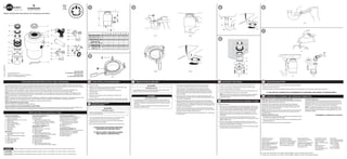
AIR SWITCH INSTALLATION
The air switch includes two different button finishes. If you wish to
change the button finish (optional), simply pry off the existing button
and snap the other button finish onto the bellows. (See Figure 11.2)
1. Drill a 33 mm wide hole into the kitchen work top, or the corner of
the sink unit, at the most convenient point for use. Some sink units
may already have a suitable hole in them which can be exposed by
removing the cap.
2. Remove the nut from the push button bellows, while keeping the
stainless steel washer and rubber gasket in place. Push one end of
the PVC tubing onto the spout of the push button bellows, feed the
other end of the tube through the hole in the work top and through
the nut underneath the work top. (See Figure 11.3)
3. Fit the push button bellows in the hole and then screw up the nut
underneath the work top until it is hand tight. Do not use a wrench
to tighten the nut. (See Figure 11.4)
4. Take the other end of the air tube and firmly push it over the spout
of the air switch, which is located on the underside of the waste
disposer. (See Figure 11.5)
DISABLING THE AIR SWITCH
The air switch can be disabled if wall switch operation is preferred.
The disposer is shipped with the switch in the “off ” position.
1. Push one end of the PVC tubing provided onto the spout of the push
button bellows. (See Figure 11.3)
2. Take the other end of the air tube and push it over the spout of the
air switch, which is located on the underside of the waste disposer.
(See Figure 11.5)
3. Depress the air switch one time until you hear the switch “click.”
Remove and discard the push button bellows and PVC tubing. The
disposer may now be activated by a wall switch.
The disposer installation is complete. Read all operating and
safety instructions in Instruction 12 before operating the disposer.
Lastly, place stopper in sink in close position. Fill sink with water,
remove stopper, turn disposer on and check for leaks.
CONNECT DISPOSER TO ELECTRICAL SUPPLY
ELECTRICAL SHOCK
• To avoid electrical shock, disconnect power before installing or
servicing disposer.
• If you are not thoroughly familiar with electric power, contact a
qualified electrician to connect disposer to electrical circuit.
• If three-prong, earth (grounded) plug is used, plug must be
inserted into three-hole, earth (grounded) receptacle.
• Do not modify plug provided with unit (if applicable).
• Improper connection of equipment earth (grounded) conductor
can result in electric shock.
• All wiring must comply with local electrical codes.
• Do not attach earth wire (ground wire) to gas supply pipe.
• Do not reconnect electrical current at main service panel until
proper earth (grounded) outlets are installed.
• If the supply cord is damaged, it must be replaced by the
manufacturer, its service agent or similarly qualified-persons
in order to avoid a hazard.
11
11
8.3
8.2
8.1
8.4
MODEL XX – XXS/N XXXXXXXXXX
PUSH RED BUTTON
TO RESET
Clear any objects from inside the disposer grind chamber before
mounting the disposer to the sink.
1. This product must be installed so that the motor reset button
located on the bottom of the disposer is readily accessible.
Keep this space clear of all objects.
2. Prior to connecting disposer to mounting assembly, detach the
perforated portion of the specification label found at the base
of the disposer, and set aside for Instruction 9 (See Figure 8.1).
3. Position disposer with three mounting tabs (1) aligned in
position to slide over mounting tracks (2). (See Figure 8.2)
4. Lift disposer, insert top end (mounting gasket) into mounting
assembly, and turn lower mounting ring to right (with
wrenchette or adjustable pliers) until mounting tabs lock over
ridges (3) on mounting ring tracks (see Figure 8.3). Make sure
all three mounting tabs are locked over ridges. Disposer will
now hang by itself.
EVOLUTION 200 AND EVOLUTION 100, MODEL 65
Insert sound baffle into sink opening, with flat side upward. (See
Figure 8.4)
CONNECT DISPOSER TO MOUNTING ASSEMBLY
PERSONAL INJURY
To avoid personal injury, do not position your head or body
under disposer; the unit could fall during installation.
8
8
MODEL XX – XX
S/N XXXXXXXXXX
PUSH RED BUTTON
TO RESET
10.3 10.4
10.5 10.6
10.210.1
(FLANGED DISCHARGE
PIPE NOT PROVIDED)
(FLANGED DISCHARGE
PIPE NOT PROVIDED)
AUSTRALIA ONLY
AUSTRALIA ONLY
DISCHARGE TUBE INSTALLATION (EVOLUTION 200 AND
EVOLUTION 100)
1. Place discharge tube (2) into Anti-Vibration Tailpipe Mount™
. Secure
with spring type hose clamp (1). (See Figure 10.1)
UK, NEW ZEALAND, HONG KONG AND IRELAND DISCHARGE
TUBE INSTALLATION (MODELS 65, 55, 45)
1. Place metal flange (6) over discharge tube (8). Insert rubber
gasket (5) with gasket lip facing the metal flange into discharge
tube. (See Figure 10.3)
2. Secure metal flange and discharge tube to disposer with two
13 mm bolts (7).
ATTACH DISCHARGE TUBE TO WASTE DRAIN PIPE
This specification label contains important information you will
need to know in the event service is required.
1. Apply the label to the front side of the disposer, where it can
be easily read.
ATTACH SPECIFICATION LABEL
10
9
10
OPERATING INSTRUCTIONS (EVOLUTION 200 AND EVOLUTION 100)
1. Remove strainer basket and plug from sink opening and run cold water.
2. Turn on wall switch or press air switch (see Figure 12.1) to
start disposer.
3. Slowly insert food waste into disposer and position strainer basket
and plug in upright position (allowing water to run through) to
minimize noise and possible ejection of material while grinding
(See Figure 12.2).
4. After grinding is complete, turn disposer off and run water for at
least 15 seconds to flush drain line.
5. Strainer basket and plug also acts as a stopper in the lower position.
(See Figure 12.3)
OPERATING INSTRUCTIONS (MODELS 65, 55, 45, LC-50)
1. Remove stopper from sink opening and run cold water.
2. Turn on wall switch or press air switch (see Figure 12.1) to
start disposer.
3. Slowly insert food waste into disposer and position stopper to
minimize noise and possible ejection of material while grinding.
(See Figure 12.4)
4. After grinding is complete, turn disposer off and run water for at
least 15 seconds to flush drain line.
DO...
• Grind food waste with minimum cold water flow of 5.7 liters per
minute (1-1/2 G.P.M.).
• Grind hard material such as small bones and fruit pits to clean
inside of grind chamber.
• Grind citrus, melon rinds, vegetables, and coffee grounds.
• After grinding, run water for at least 15 seconds to flush drain line.
• Switch off or unplug the appliance before attempting to free a
jammed rotor with an implement.
• Maintain the area underneath the disposer of any objects to be sure
you have access to the disposer reset button.
DON’T...
• Don’t use hot water when grinding food waste (although hot water
can be drained into disposer between grinding periods).
• Don’t turn off water or disposer until grinding is completed and only
sound of motor and water running is heard.
• Don’t grind large amounts of egg shells or fibrous materials like corn
husks, artichokes, etc., to avoid possible pipe blockage.
• Don’t grind non-food waste of any kind.
• Don’t use this appliance to dispose of hard materials such as glass
and metal.
• Don’t ever pour fats, oils or grease down the sink – it will block your
drains and the sewerage system.
INSTRUCTIONS PERTAINING TO RISK OF FIRE, ELECTRICAL SHOCK, OR INJURY TO PERSONS (SAVE THESE INSTRUCTIONS)
InSinkErator products are guaranteed against defects in material and
workmanship for the period of the guarantee from the date of purchase.
Evolution 200: 6 years Evolution 100: 5 years
Model 65: 4 years Model 55: 3 years
Model 45: 2 years LC-50: 1 year
SERVICE
If service is required, contact an InSinkErator Authorized Service
Center (see enclosed list) or your dealer. Guarantees are void if you
remove your disposer after installation and attempt to repair it, or if
the disposer is used for commercial purposes.
IN-HOME FULL SERVICE GUARANTEE
12.4 12.612.5
12.312.212.1
MODEL XX – XX
S/N XXXXXXXXXX
PUSH RED BUTTON
TO RESET
MODEL XX – XX
S/N XXXXXXXXXX
PUSH RED BUTTON
TO RESET
When using electronic appliances, basic precautions are always
to be followed, including:
• In Australia, product may require approval of the relevant regulator
and/or the sewerage system operator.
• If the air switch or wall switch fails to shut off or turn on disposer,
unplug power cord plug and contact your qualified trade person.
• This product is designed to dispose of normal household food
waste; inserting materials other than food waste into disposer
could cause personal injury and/or property damage. To reduce
the risk of injury, do not use the sink containing the disposer for
purposes other than food preparation (such as baby bathing or
washing hair).
• This appliance is not intended for use by persons (including
children) with reduced physical, sensory or mental capabilities,
or lack of experience and knowledge, unless they have been given
supervision or instruction concerning use of appliance by a person
responsible for their safety. Children should be supervised to
ensure that they do not play with disposer. To reduce the risk of
injury, close supervision is required when an appliance is used
near children.
• When attempting to loosen a jam in the food waste disposer,
switch off or unplug the appliance before attempting to free a
jammed rotor. Use a self service wrenchette as described in
the Releasing Disposer Jam section.
• Use long-handled tongs or pliers to remove objects from disposer.
• To reduce the risk of injury by materials that are expellable by a waste
disposer, do not operate Evolution disposers without the sound
baffle in place (See Figure 8.4). Place stopper in sink opening as shown
in Figure 12.2 or 12.4. Do not put the following into a disposer: clam
or oyster shells, caustic drain cleaners or similar products, glass,
china, or plastic, large (whole) bones, metal (such as bottle caps,
steel shot, tin cans, or utensils), hot grease or other hot liquids.
• Replace sound baffle/mounting gasket/splash baffle when worn to
help prevent entry or ejection of material and water.
• When not using disposer, leave stopper in place to reduce risk of
objects falling into disposer. Make sure disposer power switch is
turned off.
• Before pressing reset button, attempting to clear jam, or removing
objects from inside disposer, make sure disposer power switch is
turned off.
• Do not insert hands or fingers into disposer.
• FIRE HAZARD: Do not store flammable items such as rags, paper,
or aerosol cans near disposer. Do not store or use gasoline or other
flammable vapors and liquids in vicinity of disposer.
• Do not dispose of the following in the disposer: paints, solvents,
household cleaners and chemicals, automotive fluids, plastic wrap.
• Don’t fill disposer with a lot of vegetable peels all at once. Instead, turn
the water and disposer on first and then feed the peels in gradually.
• Don’t waste food. Nearly a quarter of the food we buy is thrown
away untouched: salad, bread and cakes and fruit head the list.
Three tips to stop waste and save you money: only buy, or cook,
the portions you need for the meal; check the fridge and cupboard
for food you haven’t eaten–make it your next snack or freeze it;
and make sure you leave that food off your next shopping list!
CLEANING DISPOSER
Over time, grease/food particles may accumulate in the grind
chamber and baffle, causing an unpleasant odor. To clean
the disposer:
1. Turn off disposer and disconnect power supply.
2. Reach through sink opening and clean underside of splash
baffle and inside upper lip of grind chamber with scouring pad.
3. Place stopper in sink opening and fill sink halfway with
warm water.
4. Mix 60 ml baking soda with water. Turn disposer on and
remove stopper from sink at same time to wash away
loose particles.
RELEASING DISPOSER JAM
If the motor stops while the disposer is operating, the disposer
may be jammed. To release jam:
1. Turn disposer power and water off.
2. Insert one end of the self-service wrenchette into the center
hole on the bottom of the disposer (see Figure 12.5). Work the
wrenchette back and forth until it turns one full revolution.
Remove wrenchette.
3. Reach into the disposer with tongs and remove object(s). Allow
the disposer motor to cool for 3 - 5 minutes and lightly push
red reset button on the disposer bottom (see Figure 12.6). (If
the motor remains inoperative, check the service panel for
tripped circuit breakers or blown fuses.)
12
12
UK, NEW ZEALAND, HONG KONG AND IRELAND DISCHARGE
TUBE INSTALLATION (LC-50)
1. Place metal flange (11) over discharge tube (12). (See Figure 10.4)
2. Insert rubber gasket (9) with the gasket lip facing the metal flange
into discharge tube (gasket may be pre-fitted in discharge tube).
Secure metal flange and discharge tube to disposer with one
19 mm bolt (10) (Gasket will hold in place).
AUSTRALIA DISCHARGE TUBE INSTALLATION (MODELS 65, 55,
45) (Optional straight pipe connection; connection to Caroma
Connection not supplied. Attach discharge tube to waste pipe.)
1. Insert rubber gasket (13) into discharge outlet. (See Figure 10.5)
2. Attach flanged discharge pipe (not provided) using washers (14) and
19 mm 1/4 -20 bolts (15).
AUSTRALIA DISCHARGE TUBE INSTALLATION (LC-50) (Optional
straight pipe connection; connection to Caroma Connection not
supplied. Attach discharge tube to waste pipe.)
1. Place rubber gasket (16) between disposer and flange (17). (See
Figure 10.6)
2. Tighten flange with one 19 mm bolt (18). Attach flanged discharge
pipe (not provided) using washers (19) and nuts (20).
ALL DISPOSERS CONTINUE WITH STEPS 3-5
3. Rotate disposer so that discharge tube is aligned with drain trap.
(To prevent leaks, do not pull or bend discharge tube to drain trap.)
If discharge tube is too short, you can purchase an extension from
hardware store. (Disposer must remain in vertical position to
prevent vibration.)
4. Place nut, then ferrule on discharge tube (not supplied) and tighten
on drain trap. (If you have a double sink, use separate drain traps for
both sides of sink.)
5. Ensure lower mounting ring is still securely locked over ridges on
mounting flange. (See Figure 8.2)
NOTE: You must have access to an earth (grounded) wall socket.
Any additional socket should be fitted by a qualified electrician and
properly earthed (grounded). The disposer is fitted with a molded plug
and cable.
ON/OFF CONTROL
There are two types of controls for continuous-feed disposers:
a double-pole switch and an air switch (built in for Evolution 200,
Evolution 100, and Model 65; available as an accessory on all
other models).
Double Pole Switch (1):
If a wall switch (not supplied) is required for your installation, it must
have on/off markings and be installed by a qualified tradeperson. It
should be located in a convenient position above the work surface
with a minimum of 3 mm contact separation between each pole (20
ADP switches to BS 3676). In New Zealand, please refer to AS/NZS
3000:2007 for electrical installation. Connect to a 13 amp earth
(grounded) wall socket (2) using a 13 amp cable. (See Figure 11.1)
11.1 11.3
11.4
33 mm
11.5
11.2
PROPERTY DAMAGE
• Wearing safety glasses is recommended during the installation
of the food waste disposer.
• All Evolution 200 and Evolution 100 models must be connected
to the supplied tailpipe with the supplied spring type hose clamp.
(See Figure 10.1) In Australia it is required to use the supplied
straight discharge tube with supplied spring type hose clamp.
(See Figure 10.2) Failure to use the supplied tubes and spring
type hose clamp will void the guarantee and possibly cause
premature failure of the Anti-Vibration Tailpipe Mount™
.
• Do not use plumber’s putty on any other disposer connection
other than on sink flange. Do not use thread sealants or pipe
dope. These may harm disposer and cause property damage.
• Regularly inspect disposer and plumbing fittings for water leaks,
as water leaks can cause property damage. Manufacturer cannot
be held responsible for property damage as a result of water leaks.