Rs 232 Eia 232 Serial Interface Pinout
•
0 gefällt mir•735 views

Rs 232 Eia 232 Serial Interface Pinout

Empfohlen
Weitere ähnliche Inhalte
Was ist angesagt?
Was ist angesagt? (18)
Andere mochten auch
Andere mochten auch (13)
Ähnlich wie Rs 232 Eia 232 Serial Interface Pinout
Ähnlich wie Rs 232 Eia 232 Serial Interface Pinout (20)
Kürzlich hochgeladen
Kürzlich hochgeladen (20)
Rs 232 Eia 232 Serial Interface Pinout
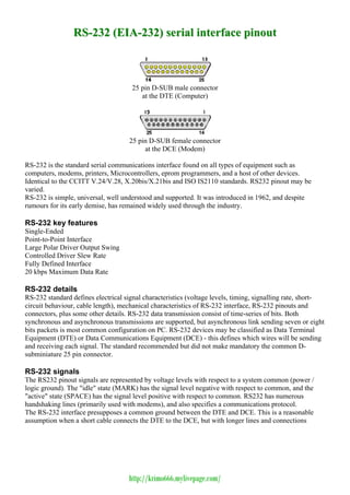
- 1. RS-232 (EIA-232) serial interface pinout 25 pin D-SUB male connector at the DTE (Computer) 25 pin D-SUB female connector at the DCE (Modem) RS-232 is the standard serial communications interface found on all types of equipment such as computers, modems, printers, Microcontrollers, eprom programmers, and a host of other devices. Identical to the CCITT V.24/V.28, X.20bis/X.21bis and ISO IS2110 standards. RS232 pinout may be varied. RS-232 is simple, universal, well understood and supported. It was introduced in 1962, and despite rumours for its early demise, has remained widely used through the industry. RS-232 key features Single-Ended Point-to-Point Interface Large Polar Driver Output Swing Controlled Driver Slew Rate Fully Defined Interface 20 kbps Maximum Data Rate RS-232 details RS-232 standard defines electrical signal characteristics (voltage levels, timing, signalling rate, short- circuit behaviour, cable length), mechanical characteristics of RS-232 interface, RS-232 pinouts and connectors, plus some other details. RS-232 data transmission consist of time-series of bits. Both synchronous and asynchronous transmissions are supported, but asynchronous link sending seven or eight bits packets is most common configuration on PC. RS-232 devices may be classified as Data Terminal Equipment (DTE) or Data Communications Equipment (DCE) - this defines which wires will be sending and receiving each signal. The standard recommended but did not make mandatory the common D- subminiature 25 pin connector. RS-232 signals The RS232 pinout signals are represented by voltage levels with respect to a system common (power / logic ground). The "idle" state (MARK) has the signal level negative with respect to common, and the "active" state (SPACE) has the signal level positive with respect to common. RS232 has numerous handshaking lines (primarily used with modems), and also specifies a communications protocol. The RS-232 interface presupposes a common ground between the DTE and DCE. This is a reasonable assumption when a short cable connects the DTE to the DCE, but with longer lines and connections http://krimo666.mylivepage.com/
- 2. between devices that may be on different electrical busses with different grounds, this may not be true. RS232 data is bi-polar. The standard specifies a maximum open-circuit voltage of 25 volts, but common signal levels are ?5 V, ?10 V, ?12 V, and ?15 V. Circuits driving an RS-232-compatible interface must be able to withstand indefinite short circuit to ground or to any voltage level up to 25 volts. From +3 to +12 volts indicates an "ON or 0-state (SPACE) condition" while A -3 to -12 volts indicates an "OFF" 1-state (MARK) condition. Some computer equipment ignores the negative level and accepts a zero voltage level as the "OFF" state. In fact, the "ON" state may be achieved with lesser positive potential. This means circuits powered by 5 VDC are capable of driving RS232 circuits directly, however, the overall range that the RS232 signal may be transmitted/received may be dramatically reduced. The output signal level usually swings between +12V and -12V. The "dead area" between +3v and -3v is designed to absorb line noise. In the various RS-232-like pinout definitions this dead area may vary. For instance, the definition for V.10 has a dead area from +0.3v to -0.3v. Many receivers designed for RS-232 are sensitive to differentials of 1v or less. RS232 pinout Pin RS-232 pin name ITU-T Dir RS-232 pinout Description 1 GND 101 Shield Ground 2 TXD 103 Transmit Data 3 RXD 104 Receive Data Request to Send. Used by the Data Terminal to signal the Data 4 RTS 105 Set that it may begin sending data. The Data Set will not send out data with out this signal, active high. Clear to Send. Used by the Data Set to signal the Data Terminal 5 CTS 106 that it may begin sending data. The Data Terminal will not send out data with out this signal, active high. Data Set Ready. Used by the Data Set to signal to the Data 6 DSR 107 Terminal that it is ready for operation and ready to receive data, active high. 7 GND 102 System Ground Carrier Detect. Used by the Data Set to indicate to the Data 8 CD 109 Terminal that the Data set has detected a carrier (of another device). 9 - - RESERVED 10 - - RESERVED 11 STF 126 Select Transmit Channel 12 S.CD ? Secondary Carrier Detect 13 S.CTS ? Secondary Clear to Send 14 S.TXD ? Secondary Transmit Data 15 TCK 114 Transmission Signal Element Timing 16 S.RXD ? Secondary Receive Data 17 RCK 115 Receiver Signal Element Timing 18 LL 141 Local Loop Control 19 S.RTS ? Secondary Request to Send http://krimo666.mylivepage.com/
- 3. Data Terminal Ready. Used by the Data Terminal to signal 20 DTR 108 to the Data Set that it is ready for operation, active high. 21 RL 140 Remote Loop Control Ring Indicator. Used by the Data Set to indicate to the 22 RI 125 Data Terminal that a ringing condition has been detected. 23 DSR 111 Data Signal Rate Selector 24 XCK 113 Transmit Signal Element Timing 25 TI 142 Test Indicador RS232 pinout details Data is transmitted and received on pins 2 and 3 respectively. Data Set Ready (DSR) is an indication from the Data Set (i.e., the modem or DSU/CSU) that it is on. Similarly, DTR indicates to the Data Set that the DTE is on. Data Carrier Detect (DCD) indicates that a good carrier is being received from the remote modem. Pins 4 RTS (Request To Send - from the transmitting computer) and 5 CTS (Clear To Send - from the Data set) are used to control. In most Asynchronous situations, RTS and CTS are constantly on throughout the communication session. However where the DTE is connected to a multipoint line, RTS is used to turn carrier on the modem on and off. On a multipoint line, it"s imperative that only one station is transmitting at a time (because they share the return phone pair). When a station wants to transmit, it raises RTS. The modem turns on carrier, typically waits a few milliseconds for carrier to stabilize, and then raises CTS. The DTE transmits when it sees CTS up. When the station has finished its transmission, it drops RTS and the modem drops CTS and carrier together. Clock signals (pins 15, 17, & 24) are only used for synchronous communications. The modem or DSU extracts the clock from the data stream and provides a steady clock signal to the DTE. Note that the transmit and receive clock signals do not have to be the same, or even at the same baud rate. RS232 data flow diagram RS232 data usually is sent as a packet with 7 or 8 bit words, start, stop, parity bits (may be varied). Sample transmission shown on picture: Start bit (active low, usually between +3v and +15v) followed by data bits, parity bit (depends on protocol used) and finished by stop bit (used to bring logic high, usually between -3v and -15v). +15V | 0 1 0 0 0 0 0 0 1 0 1 1 | _ ___________ _ | | | | | | | | | | | | | | | | | | | | | | | | | | | | +3V | | | | | | | 0V |- | | | - | | | - -3V | | | | | | | | | | | | | | | | | | | | | | | | | | | | |---| |_| |_| |____----- | -15V | Start Data P Stop http://krimo666.mylivepage.com/
- 4. RS-232 specifications SPECIFICATIONS RS232 SINGLE Mode of Operation -ENDED 1 DRIVER Total Number of Drivers and Receivers on One Line 1 RECVR Maximum Cable Length 50 FT. Maximum Data Rate 20kb/s Maximum Driver Output Voltage +/-25V Driver Output Signal Level (Loaded Min.) Loaded +/-5V to +/-15V Driver Output Signal Level (Unloaded Max) Unloaded +/-25V Driver Load Impedance (Ohms) 3k to 7k Max. Driver Current in High Z State Power On N/A Max. Driver Current in High Z State Power Off +/-6mA @ +/-2v Slew Rate (Max.) 30V/uS Receiver Input Voltage Range +/-15V Receiver Input Sensitivity +/-3V Receiver Input Resistance (Ohms) 3k to 7k http://krimo666.mylivepage.com/