1. 1. MPLS – LDP - Xconnects
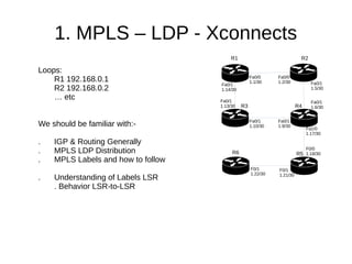
Loops:
R1 192.168.0.1
R2 192.168.0.2
… etc
We should be familiar with:-
. IGP & Routing Generally
. MPLS LDP Distribution
. MPLS Labels and how to follow
. Understanding of Labels LSR
. Behavior LSR-to-LSR
R5
R1 R2
R3 R4
R6
Fa0/1
1.6/30
Fa0/0
1.1/30
Fa0/0
1.2/30 Fa0/1
1.5/30
Fa0/1
1.9/30
Fa0/1
1.10/30
Fa0/1
1.14/30
Fa0/1
1.13/30
Fa1/0
1.17/30
F0/0
1.18/30
F0/1
1.21/30
F0/1
1.22/30
2. 2. MPLS – LDP - Xconnects
Adding CE Portion to the Network
Interconnects:
CE-R7 <==> R1
Fa0/1 Fa1/0
CE-R8 <==> R6
Fa0/0 Fa0/0
We/ISP will try and provide CE with a
point-to-point connection (l2circuit)
and we use MPLS for this.
After this is done, CE can configure
their own IP between CE.R7 – CE.R8
R5
R1 R2
R3 R4
R6
Fa0/1
1.6/30
Fa0/0
1.1/30
Fa0/0
1.2/30 Fa0/1
1.5/30
Fa0/1
1.9/30
Fa0/1
1.10/30
Fa0/1
1.14/30
Fa0/1
1.13/30
Fa1/0
1.17/30
F0/0
1.18/30
F0/1
1.21/30
F0/1
1.22/30
R8 R6
R7
P-to-P
3. 3. MPLS – LDP - Xconnects
Configs on R1
R1#show run interface fa 1/0
!
interface FastEthernet1/0
description r1-ce7
no ip address
xconnect 192.168.0.6 99 encapsulation mpls
End
NOTE: Nothing special on CE.R7 & CE.R8 – xconnects
are totally transparent to customers
Configs on R6
R6#show run interface fa0/0
!
interface FastEthernet0/0
description r6-ce8
no ip address
xconnect 192.168.0.1 99 encapsulation mpls
end
VCID 99
R5
R1 R2
R3 R4
R6
Fa0/0
1.1/30
Fa0/0
1.2/30
Fa0/1
1.9/30
Fa0/1
1.10/30
Fa0/1
1.14/30
Fa0/1
1.13/30
Fa1/0
1.17/30
F0/0
1.18/30
F0/1
1.21/30
F0/1
1.22/30
R8 R6
R7
P-to-P
4. 4. MPLS – LDP - Xconnects
Testing Xconnect on PE R1<==>R6
R1#show xconnect all
XC ST Segment 1 S1 Segment 2 S2
------+---------------------------------+--+---------------------------------+--
UP ac Fa1/0(Ethernet) UP mpls 192.168.0.6:99 UP
R1#show xconnect interface Fa1/0 detail
XC ST Segment 1 S1 Segment 2 S2
------+---------------------------------+--+---------------------------------+--
UP ac Fa1/0(Ethernet) UP mpls 192.168.0.6:99 UP
Interworking: none Local VC label 16
Remote VC label 27
R6#show xconnect all
XC ST Segment 1 S1 Segment 2 S2
------+---------------------------------+--+---------------------------------+--
UP ac Fa0/0(Ethernet) UP mpls 192.168.0.1:99 UP
R6#show xconnect interface Fa0/0 detail
XC ST Segment 1 S1 Segment 2 S2
------+---------------------------------+--+---------------------------------+--
UP ac Fa0/0(Ethernet) UP mpls 192.168.0.1:99 UP
Interworking: none Local VC label 27
Remote VC label 16
VCID99
VCID99
R5
R1 R2
R3 R4
R6
Fa0/1
1.6/30
Fa0/0
1.1/30
Fa0/0
1.2/30 Fa0/1
1.5/30
Fa0/1
1.9/30
Fa0/1
1.10/30
Fa0/1
1.14/30
Fa0/1
1.13/30
Fa1/0
1.17/30
F0/0
1.18/30
F0/1
1.21/30
F0/1
1.22/30
R8 R6
R7
Local Label 16
Local Label 27
P-to-P
5. 5. MPLS – LDP - Xconnects
Xconnect – Labels Local/Remote & VCID
R1#show mpls forwarding-table
Local Outgoing Prefix Bytes tag Outgoing Next Hop
tag tag or VC or Tunnel Id switched interface
16 l2ckt(99) 73919 none point2point
23 22 192.168.0.6/32 0 Fa0/1 192.168.1.13
19 192.168.0.6/32 0 Fa0/0 192.168.1.2
Labels on MY LOCAL LOOP
R1 Local Loop (192.168.0.1) Label 23
R6 Local Loop (192.168.0.6) Label 22
Label on DEST LOOP R1 & R6
R1 → R6 fa0/1 use Label 22
R6 → R1 fa0/1 use Label 20
R6#show mpls forwarding-table
Local Outgoing Prefix Bytes tag Outgoing Next Hop
tag tag or VC or Tunnel Id switched interface
22 20 192.168.0.1/32 0 Fa0/1 192.168.1.21
27 l2ckt(99) 78453 none point2point
Local Label 16
Local Label 27
VCID99
R5
R1 R2
R3 R4
R6
Fa0/1
1.6/30
Fa0/0
1.1/30
Fa0/0
1.2/30 Fa0/1
1.5/30
Fa0/1
1.9/30
Fa0/1
1.10/30
Fa0/1
1.14/30
Fa0/1
1.13/30
Fa1/0
1.17/30
F0/0
1.18/30
F0/1
1.21/30
F0/1
1.22/30
R8 R6
R7
L22
L20
P-to-P
6. 6. MPLS – LDP - Xconnects
Xconnect – Labels Local/Remote & VCID
R6 → R1 : Fill in the Blanks
R6#show mpls l2transport vc 99 detail
Local interface: Fa0/0 up, line protocol up, Ethernet up
Destination address: 192.168.0.1, VC ID: 99, VC status: up
Next hop: 192.168.1.21
Output interface: Fa0/1, imposed label stack {20 16}
Create time: 03:33:09, last status change time: 03:33:06
Signaling protocol: LDP, peer 192.168.0.1:0 up
MPLS VC labels: local 27, remote 16
Group ID: local 0, remote 0
MTU: local 1500, remote 1500
Remote interface description: r1-ce7
R6#show xconnect interface fa0/0 detail
XC ST Segment 1 S1 Segment 2 S2
------+-----------------------------+--+----------------------------+--
UP ac Fa0/0(Ethernet) UP mpls 192.168.0.1:99 UP
Interworking: none Local VC label 27
Remote VC label 16
Local Label 16
Local Label 27
VCID99
R5
R1 R2
R3 R4
R6
Fa0/0
1.1/30
Fa0/0
1.2/30
Fa0/1
1.9/30
Fa0/1
1.10/30
Fa0/1
1.14/30
Fa0/1
1.13/30
F0/1
1.21/30
F0/1
1.22/30
R8 R6
R7
L
P-to-P
7. 7. MPLS – LDP - Xconnects
Xconnect – Labels Local/Remote & VCID
R1#show mpls l2transport vc 99 detail
Local interface: Fa1/0 up, line protocol up, Ethernet up
Destination address: 192.168.0.6, VC ID: 99, VC status: up
Next hop: 192.168.1.13
Output interface: Fa0/1, imposed label stack {22 27}
Create time: 03:04:31, last status change time: 02:59:26
Signaling protocol: LDP, peer 192.168.0.6:0 up
MPLS VC labels: local 16, remote 27
Group ID: local 0, remote 0
MTU: local 1500, remote 1500
Remote interface description: r6-ce8
R1#show xconnect inter fa1/0 detail
XC ST Segment 1 S1 Segment 2 S2
------+------------------------------+--+---------------------------------+--
UP ac Fa1/0(Ethernet) UP mpls 192.168.0.6:99 UP
Interworking: none Local VC label 16
Remote VC label 27
Local Label 16
Local Label 27
VCID99
R5
R1 R2
R3 R4
R6
Fa0/0
1.1/30
Fa0/0
1.2/30
Fa0/1
1.9/30
Fa0/1
1.10/30
Fa0/1
1.14/30
Fa0/1
1.13/30
F0/1
1.21/30
F0/1
1.22/30
R8 R6
R7
Label
20?
L22
P-to-P
8. 9. MPLS – LDP - Xconnects
Thank You – kjteoh 11/12/2015
Larger Diagram for reference
Be proficient with MPLS-Xconnects
(junos l2ckt) – Next is:
L3VPN-RD-RT - MP-BGP required
Local Label 16
Local Label 27
VCID99P
To
P
R5
R1 R2
R3 R4
R6
Fa0/0
1.1/30
Fa0/0
1.2/30
Fa0/1
1.9/30
Fa0/1
1.10/30
Fa0/1
1.14/30
Fa0/1
1.13/30
F0/1
1.21/30
F0/1
1.22/30
R8 R6
R7
Label
20?
L22