Cálculos para bombas del sistema de agua de la planta
•
0 gefällt mir•40 views

Cálculos para bombas del sistema de agua de la planta

Empfohlen
Empfohlen
Weitere ähnliche Inhalte
Was ist angesagt?
Was ist angesagt? (20)
Ähnlich wie Cálculos para bombas del sistema de agua de la planta
Ähnlich wie Cálculos para bombas del sistema de agua de la planta (20)
Mehr von JUAN ALTAMIRANO ROJAS
Kürzlich hochgeladen
Kürzlich hochgeladen (20)
Cálculos para bombas del sistema de agua de la planta
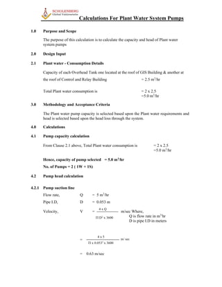
- 1. Calculations For Plant Water System Pumps 1.0 Purpose and Scope The purpose of this calculation is to calculate the capacity and head of Plant water system pumps 2.0 Design Input 2.1 Plant water - Consumption Details Capacity of each Overhead Tank one located at the roof of GIS Building & another at the roof of Control and Relay Building = 2.5 m3 /hr Total Plant water consumption is = 2 x 2.5 =5.0 m3 /hr 3.0 Methodology and Acceptance Criteria The Plant water pump capacity is selected based upon the Plant water requirements and head is selected based upon the head loss through the system. 4.0 Calculations 4.1 Pump capacity calculation From Clause 2.1 above, Total Plant water consumption is = 2 x 2.5 =5.0 m3 /hr Hence, capacity of pump selected = 5.0 m3 /hr No. of Pumps = 2 ( 1W + 1S) 4.2 Pump head calculation 4.2.1 Pump suction line Flow rate, Q = 5 m3 /hr Pipe I.D, D = 0.053 m Velocity, V = m/sec Where, Q is flow rate in m3/ hr D is pipe I.D in meters = = 0.63 m/sec 4 x Q D2 x 3600 4 x 5 x 0.0532 x 3600 m/ sec
- 2. i. Frictional Head Loss in Pipe HL (s) = 6.815 x x Where, V is velocity in m/sec D is pipe I.D in meters C is co-efficient of friction HL (s) = 6.815 x x = 0.013 For a pipe length of 5 meters HL(s) = 0.06 mwc ii. Head Loss due to Fittings HL (f) = Where, HL (f) is frictional head loss in pipe in mwc / metre V is velocity in m/sec. g is Acc. due to gravity = 9.81m/sec2 K is resistance coefficient Fittings Gate Valve - 1 No. K = 0.152 Strainer - 1 No. K = 2.5 Entry - 1 No. K = 0.5 Total K = 3.152 HL(f) = = HL(f) = 0.064 mwc KV2 2g 2 x 9.81 V C 1 1.167 1.852 = 120 120 1.852 1 1.167 D mwc/m length of pipe KV2 2g 0.053 0.63 3.152 x (0.63)2
- 3. iii. Total Pressure Drop = (HL(S) + HL(f)) = 0.06 + 0.064 = 0.124 mwc 4.2.2 Head loss in discharge pipeline for DN 50 Flow rate, Q = 5 m3 /hr Pipe I.D, D = 0.053 m Velocity, V = m/sec Where, Q is flow rate in m3/ hr D is pipe I.D in meters = = 0.63 m/sec i. Frictional Head Loss in Pipe HL (p) = 6.815 x x Where, V is velocity in m/sec D is pipe I.D in meters C is co-efficient of friction HL (p) = 6.815 x x = 0.013 For a pipe length of 135 meters HL(p) = 1.755 mwc ii. Head Loss due to Fittings HL (f) = Where , HL (f) is frictional head loss in pipe in mwc / metre V is velocity in m/sec. g is Acc. due to gravity = 9.81m/sec2 K is resistance coefficient Fittings Gate Valve - 1 No. K = 0.152 4 x Q D2 x 3600 4 x 5 x 0.0532 x 3600 m/ sec V C 1 1.167 1.852 = 120 120 1.852 1 1.167 D mwc/m length of pipe KV2 2g 0.053 0.63
- 4. Elbows - 10 Nos. K = 5.7 Check Valve - 1 No. K = 2.5 Tees - 2 Nos. K = 0.76 Total K = 9.112 HL(f) = = HL(f) = 0.184 mwc iii. Total Pressure Drop = (HL(P) + HL(f)) = 1.755 + 0.184 = 1.939 mwc Pump discharge head = Pump suction head + Pump suction pipe losses + Discharge pipe losses +Static Head + Residual pressure = 4 + 0.116 + 1.939 +10 + 5 = 21.055 m Consider 10% margin on friction loss Head selected = 25 MWC 5.0 Results Quantity = 2 ( 1 W+ 1 S) for Ittin Sub-Station = 2 ( 1 W+ 1 S) for Al-Qarm Sub-Station Capacity of each Pump = 5.0 m3 /hr Selected Head = 25 MWC KV2 2g 2 x 9.81 9.112 x (0.63)2