SlideShare ist ein Scribd-Unternehmen logo
1 von 41
Downloaden Sie, um offline zu lesen
1
CHAPTER I
INTRODUCTION
What is CAD?
 Computer Aided Design
 Allows you to accomplish design and drafting activities using a computer.
◦ Design – is a broad field involving the process of making an idea into a real product or system.
◦ Drafting – is generally known as the production of drawings that are used to document a design
from manufacturing or construction.
Why Use CAD?
 Accuracy - It stores numeric data with great precision.
 Productivity for Repetitive Operations - Shaped, drawings and elements can easily be duplicated
(copy/paste)
 Sharing the CAD file with other software programs - Drawings can be imported to other programs.
Getting to know AutoCAD
Parts of the AutoCAD Window
 Title bar - Contains the program name and the title of the current drawing and its path.
 Standard toolbar - Contains standard commands use in the program.
 Menu bar - Bar that contains all the commands in AutoCAD.
 Layers and Properties toolbar - Contains buttons and commands use to manipulate the properties and
layers of the drawing.
 Drawing area - Blank middle section of the screen. Where you draw your shapes
 Crosshair cursor - Pointer
 User coordinate system icon - Indicates the positive direction for the X and Y coordinates
 Model and Layout tabs - Use to shift between different views.
 Command window - Is where you tell the program what to do and where the program tells you what’s
going on.
 Status bar - Displays the status of the program’s commands: Snap, Grid, Ortho, Otrack , LWT, Model
2
Drop-Down Menus
 View - Contains tools for controlling the display of your drawing file.
 Insert - Contains commands for placing drawings and images or parts of them inside other drawings.
 Format - Contains commands for setting up general parameters for a new drawing.
 Tools - Contains special tools for use while you are working on the current drawing.
 Draw - Contains commands for displaying new objects (lines, circles) on the screen.
 Dimension - Contains commands for dimensioning a drawing.
 Modify - Contains commands for changing existing objects in the drawing
 Window - Contains commands for displaying currently open windows and lists currently open drawing
files.
Command Entry
 Methods of Entering Commands:
◦ Toolbars - Select the command by picking an icon from a toolbar
◦ Pull-down Menu - Select the command from a pull-down menu
◦ Screen (side) Menu - Select the command from the screen (side) menu.
◦ Keyboard - Type the command name, command alias or CTRL (accelerator) keys at the keyboard.
 Using the Mouse
◦ Left button – PICK
 Used to select commands or pick locations on the screen.
◦ Right button – Enter or shortcut Menu
 This button either performs the same function as the enter key or produces a shortcut menu.
◦ Middle button or wheel – Pan / Zoom
 Press and Drag – Pan the drawing about on the screen.
 Wheel – zoom in or zoom out
Function Keys
 F1 – Help. Opens help window providing written explanation on commands and variables.
 F2 – Flipscreen. Activates a text window showing the previous command line activity (command history)
 F3 – Osnap Toggle. Turns the Osnap on or off.
 F4 – Tablet. Turns Tabmode variable on or off.
 F5 – Isoplane. Isometric Style Snap and Grid Setting, Toggles the cursor to dram on one of the isometric
planes.
 F6 – Coords. Toggles the coordinate display between cursor tracking mode and off.
 F7 – Grid. Turns the grid on or off.
 F8 – Ortho. Turns the ortho on or off.
 F9 – Snap. Turns the snap on or off.
 F10 – Polar. Turns the polar on or off.
 F11 – Osnap Tracking. Turns the osnap tracking on or off.
 F12 – Dyn. Turns the dynamic input on or off.
Drawing Aid
 SNAP (F9)
◦ Grid Snap – forces the cursor to snap to regular intervals (grid)
◦ Polar Snap – forces the cursor to snap regular intervals along angular lines.
 GRID (F7) - Used as visual reference of units and lengths.
 ORTHO (F8) - Lines are forced to an orthogonal alignment (only horizontal or vertical) when drawing.
 Polar (F10) - Makes it easy to draw lines at regular angular increments, such as 30, 45 and 90 degrees.
 OSNAP (F3, Object Snap)
 OTRACK (F11)
 DYN (F12) - A feature that helps you visualize and specify coordinates when drawing lines, arcs, circles
and the like.
3
Basic Commands in AutoCAD
Standard Toolbar
Drawing Toolbar Modify Toolbar
CHAPTER 2
BASIC COMMANDS TO GET STARTED
Drawing Icons/Toolbars
 Construction Lines - Lines that extend to infinity in one or both directions. It be used as references for
creating other objects.
 Polyline - An object composed of one or more connected line segments or circular arcs treated as a single
object. Also called pline.
 Polygon - Used to create closed polylines with between 3 and 1,024 equal-length sides.
 Spline - A spline is a smooth curve that passes through or near a given set of points. You can control how
closely the curve fits the points.
 Ellipse - The shape of an ellipse is determined by two axes that define its length and width. The longer
axis is called the major axis, and the shorter one is the minor axis.
 Ellipse Arc
 Point - Point objects are useful as nodes or reference geometry for object snaps and relative offsets.
 Text
4
The Box
Line Command
 Line Commands
o Draws a line between locations on existing lines, between geometric figures, or between points
that you choose anywhere on the screen.
o Designation of the points is either by clicking on the screen or entering coordinates (X and Y).
 To use line command
o Click line icon
o Type the word “line” [enter]
o Type the letter “l” [enter]
Note: AutoCAD is not case sensitive
Using Coordinates
For 2D (Two-Dimensional)
X and Y
For 3D (Three-Dimensional)
X, Y and Z
Using Coordinates in Drawing Lines
Relative Cartesian/Polar Coordinates
 Uses relative X and Y coordinates.
 Relies on a distance and an angle relative to the last point specified.
 “@”  lets AutoCAD knows you’re using relative coordinates.
Absolute Cartesian/Polar Coordinates
 Uses the absolute distances in the Cartesian plane.
5
Drawing Box Using Cartesian Coordinates
 Erase everything
 Click erase icon or type word “erase” or “e”
 Type “all” and
 Click line icon (“line” or “l”)
 Specify the first point, type 3,3
 Type @6,0
 Type @0,5
 Type @-6,0
 Type c
Note: “C” stands for close, connects the last point of the line to the first point.
Using Relative Polar Coordinates
 Erase everything.
 Start line command.
 Type 3,3
 Type @6<0
 Type @5<90
 Type @6<180
 Type c
Offset Command - Creates a new object whose shape parallels the shape of a selected object. Offsetting a
circle or an arc creates a larger or smaller circle or arc, depending on which side you specify for the offset.
You can offset:
 Lines
 Arcs
 Circles
 Ellipses and elliptical arcs (resulting in an oval-shaped spline)
 2D polylines
 Construction lines (xlines) and rays
 Splines
Offset Commands Involves 3 steps
1. Setting the offset distance.
2. Picking the object to offset
3. Indication the offset direction
Offsetting the Lines
1. Click Offset icon or type “offset” or “o”.
2. Specify the offset distance 0.5 [enter]
3. Place the pickbox on one of the lines and click. The selected line ghosts and the cursor changes back
to crosshair, and the prompt changes to Specify point on side to offset:
4. Pick point somewhere inside the box.
5. Press enter to end the offset command.
6. Do the same to the other 3 lines.
6
Trimming of line
You can trim objects so that they end precisely at boundary edges defined by other objects.
For example, you can clean up the intersection of two walls smoothly by trimming.
An object can be one of the cutting edges and one of the objects being trimmed. For example, in the illustrated
light fixture, the circle is a cutting edge for the construction lines and is also being trimmed.
When you trim several objects, the different selection methods can help you choose the current cutting edges
and objects to trim. In the following example, the cutting edges are selected using crossing selection.
You can trim objects to their nearest intersection with other objects. Instead of selecting cutting edges, you press
ENTER. Then, when you select the objects to trim, the nearest displayed objects act as cutting edges. In this
example, the walls are trimmed so that they intersect smoothly.
Extend Command
Extending operates the same way as trimming. You can extend objects so they end precisely at boundary
edges defined by other objects. In this example, you extend the lines precisely to a circle, which is the
boundary edge.
7
Fillet Command
A fillet connects two objects with an arc that is tangent to the objects and has a specified radius.
You can fillet: Arcs, Circles, Ellipses and elliptical arcs, Lines, Polylines, Rays, Splines, Xlines, 3D solids
Set the Fillet Radius
The fillet radius is the radius of the arc that connects filleted objects. Changing the fillet radius affects subsequent
fillets. If you set the fillet radius to 0, filleted objects are trimmed or extended until they intersect, but no arc is
created.
Drawing the box.
Step by step instruction:
1. Start with a new sheet or erase everything by clicking erase icon or type word “erase” or “e”. Type “all”
and (enter)
2. Click line icon (or type “line” or “l”) (enter)
3. Specify the first point, type 3,3 (enter)
4. Type @6,0 (enter)
5. Type @0,5 (enter)
6. Type @-6,0 (enter)
7. Type c
8
8. Type zoom (enter) and a (enter) to enlarge the drawing and placed the drawing in the center of the
screen
9. Click offset icon (or type “offset” or “o”) (enter)
10. For the offset distance type 0.5 (enter)
11. Click the topmost line, put the mouse pointer somewhere in the middle of the box, and then click.
12. Click the right line and click at the center
13. Click the bottom line and click at the center
14. Click the left line and click at the center
15. Press (enter) or Esc to stop the offset command
16. Click the fillet icon (or type “fillet” or “f”) (enter)
17. Click the top inner line and the right inner line
18. Click fillet icon again (or type “fillet” or “f”) (enter)
19. Click the right inner line and the bottom inner line
20. Click fillet icon again (or type “fillet” or “f”) (enter)
21. Click the bottom inner line and left inner line
22. Click the fillet icon again (or type “fillet” or “f”) (enter)
23. Click the left inner line and top inner line
Note: you can press (enter) to repeat previous command
9
24. Click offset icon (or type “offset” or “o”) (enter)
25. Offset distance = 0.5
26. Click the inner right line, and click at the center of the box
27.  (enter) to end offset command
28. Click offset icon (or type “offset” or “o”) (enter)
29. Offset distance = 2.0
Note: you need to start a new offset command if you want to change the offset distance.
30. Click extend icon (or type “extend” or “ex”) (enter)
31. You will be asked for the boundary edges. Click the outer lower line. (enter)
32. Then click the two newly created line (the one created by using offset command)
33. Click trim icon (or type “trim” or “tr”)
34. You will be asked for the cutting edges, click the 2 lines you just extended and the 2 bottom lines. Press

35. You can start trimming or remove the unwanted lines in the drawing
36. Click the 2 bottom lines in the middle of the 2 vertical cutting edges
10
37. Click the 2 inner lines above the bottom lines
CHAPTER 3
SETTING UP A DRAWING
Drawing Units
 Every object you create is measured in drawing units.
 Before you start to draw, you must decide what one drawing unit will represent based on what you plan
to draw.
 Then you create your drawing at actual size with that convention.
 For example, a distance of one drawing unit typically represents one millimeter, one centimeter, one inch,
or one foot in real-world units.
Setting the Drawing Units
Choose Format  Units
(Open Drawing Units Dialog Box)
Linear Units
› Architectural - This type of uses feet and inches with fractions.
› Decimal - Uses decimal units that can represent any linear unit of measurement.
› Engineering - Units are equivalent to Architectural units except that inches were displayed as decimals
rather than fractions.
› Fractional - Everything is in inches (centimeters)
› Scientific - Uses Scientific Notation.
Before trimming
After trimming
11
Angular Units
› Decimal - Uses 360 degrees in a circle.
› Deg/Min/Sec - Uses traditional system for measuring angles.
› Grads - Unit uses 400 grads in a circle
› Radians - Uses 2 radians
› Surveyor - Use bearings from north and south directions.
Drawing Size
Grid
› The grid is a rectangular pattern of dots or lines that extend over the area you specify as the grid limits.
Using the grid is similar to placing a sheet of grid paper under a drawing. The grid helps you align objects
and visualize the distances between them. The grid is not plotted.
› Snap mode restricts the movement of the crosshairs to intervals that you define. When Snap mode is on,
the cursor seems to adhere, or "snap," to an invisible rectangular grid. Snap is useful for specifying
precise points with the arrow keys or the pointing device.
› Grid mode and Snap mode are independent but are often turned on at the same time.
› To turn on the grid, press F7.
Drawing Limits
› The user-defined rectangular boundary of the drawing area covered by dots when the grid is turned on.
› Default lower point is 0,0
Note: Symbols:
‘  feet
“  inch
Steps in saving AutoCAD drawings.
1. Click save icon or go to file, then choose save (or save as)
2. This will open the Save as Dialog box.
12
3. In the Save in drop down list, choose the drive and/or folder where you want to save your drawing.
4. If you want to create a new folder, click the New Folder icon or press Alt+5.
5. In the filename textbox, type in the name of the file.
6. If you want to change the format of the drawing (compatibility purposes), choose from the drop down
menus of Files of Type.
7. Click save.
8. The name of your file is now visible at the upper left corner of the AutoCAD window.
CHAPTER 4
DRAWING STRATEGIES 1
CABIN A-1
Basic Floor Plan of the Cabin
Bedroom
13
In order to draw the figure above it is recommended that you divide the drawing in different divisions.
Divisions:
D1: Laying out of the Exterior Wall Lines
D2: Laying out of the Interior Wall Lines
D3: Cutting Openings in the Walls
D4: Drawing of Doors
D5: Drawing of Sliding Door
D1. Laying out of the Exterior Wall Lines.
Step 1. Setup drawing parameters:
› Length
 Type  Architectural
 Precision  0’-0 1/16”
› Angle
 Type  Decimal Degree
 Precision  0.00
› Units to Scale  inches
› Drawing Limits
 Lower left  0,0
 Upper right  60’,40’
› Filename: Cabin_A
› Filetype: AutoCAD 2007 Drawing
14
Step 2. Make the outside box with the dimension of 25’ (feet) x 16’ (feet)
a. Start line command
b. First point, type: 3,3
c. Next point: @25’,0
d. Next point: @0, 16’
e. Next point: @-25’,0
f. Type “c”
Step 3. Make the inner box with the offset distance of 6” (inches)
a. Start the offset command
b. Offset distance is 6”
c. Click the top line, then click the center of the box
d. Click the right line, then click the center of the box
e. Click the left line and click the center of the box
f. Click the bottom line and click the center of the box
Step 4. Remove the intersecting line by using fillet.
a. Start fillet command by clicking the fillet icon or by typing “f”
b. Click the upper line, then click the right line
c. Start the fillet command again by either clicking the icon, typing “f” or pressing the enter key ( )
d. Click the right line and the bottom line
e. Start the fillet command again
f. Click the bottom line and the left line
g. Start the fillet command again
h. Click the left line and the upper line
1.1. D2: Laying out of the Interior Wall Lines
15
Step 1. Make the internal wall divisions by using offset, fillet and trim commands. (Bedroom)
a. Start offset command
b. Offset distance is 9’4”’
c. Click the inside line of the left exterior wall
d. Click somewhere in the center of the box
e. To stop offset command, press
f. Start offset command again to change the offset distance to 4”
g. Click the new line
h. Click somewhere in the right side of the line
i. Stop the current offset command
j. Start offset command again
k. Offset distance is 6’6”
l. Click the inside line of the upper exterior wall
m. Click somewhere in the middle of the box
n. End and restart offset command
o. Offset distance is 4”
p. Click the newly formed line, and click somewhere under the new line.
q. End offset command
16
r. Start fillet command
s. Click the two outer lines to joined them
t. Start fillet command again, and click the two inner lines.
u. To remove the intersecting lines in the drawing, zoom and trim commands will be use.
 Zoom
 Allows user to increase or decrease the magnification of the view of the current drawing in the
drawing area.
 Types of Zoom:
o Zoom to Magnify a Specified Rectangular Area – allows the user to quickly zoom on a
rectangular area of the drawing by specifying two diagonal corners of the area of interest.
o Zoom in Real Time - zoom dynamically by moving your pointing device up or down. The
scroll button of the mouse can also be used to zoom in and out of the drawing.
o Zoom to View All Objects in the Drawing
 ZOOM Extents displays a view with the largest possible magnification that includes
all of the objects in the drawing. This view includes objects on layers that are turned
off but does not include objects on frozen layers.
 ZOOM All displays either the user-defined grid limits or the drawing extents,
whichever view is larger.
17
i. Click zoom window icon or type “z” then create a small rectangle/window in the area to be magnified.
j. Click trim icon or type “tr” . For cutting edges, click the two interior wall lines and press .
v. For the part to be trimmed, click the inside exterior wall line between the two interior wall lines. And
press .
w. To view the entire drawing, type “z” (enter), then “a” (enter).
x. Clean the lower area of the drawing using zoom and trim.
Step 2. Make the internal wall divisions by using offset, fillet and trim commands. (Bathroom).
a. Start offset command
b. Offset distance is 6’
c. Click the inside line of the left exterior wall
d. Click somewhere in the center of the box
18
e. To stop offset command, press
f. Start offset command again to change the offset distance
g. Offset distance is 4”
h. Click the newly offsetted line
i. Click somewhere in the right side of the line
j. Stop the current offset command
k. With the use of zoom and trim, remove the short portion of the intersected wall lines between the two
new wall lines.
19
ACTIVITY Drawing parameters:
› Length
 Type  Architectural
 Precision  0’-0 1/16”
› Angle
 Type  Decimal Degree
 Precision  0.00
› Units to Scale  inches
› Drawing Limits
 Lower left  0,0
 Upper right  60’,60’
› Filename: Act 4.1
› Filetype: AutoCAD 2007 Drawing
20
D3: Cutting Openings in the Walls
Step 1. Creating the opening for the front and back doors (Exterior doors).
a. Click the offset icon, then type 6” to set the distance.
b. Click the two innermost interior lines and offset it to the center.
c. End and restart the offset commands, set the offset distance to 3’. And offset the new lines.
d. Extend the new lines through the external walls.
e. Trim the lines to create the opening.
21
Step 2. Cutting the Interior Openings.
a. Start offset command and set the distance to 6”.
b. Offset the lines with the “x” in the figure below.
c. Restart the offset command and set the distance to 2’6”.
d. Offset the new lines.
e. Use extend and trim to remove the lines and create the opening.
Step 3. The 7’ Opening.
a. Offset a wall line by 12”.
b. Offset the new line by 7’.
c. Extend both new lines through the walls.
d. Trim the new lines and the wall lines to create the opening.
22
ACTIVITY Continue previous activity and create the openings for your drawing.
Upper Part of the Office
Lower Part of the Office
23
D4: Creating the Doors
Object Snaps.
 Enables the user to snap to existing object endpoints, midpoints, centers, intersections and etc.
 Object snaps must be active for the user to snap to desired objects.
 Object Snap Modes:
o Center - finds the center of a circle, arc, donut or any circular object.
o Endpoint - snaps to the endpoint of a Line, Pline, Spline, or Arc
24
o Insert – locates the insertion point of Text or a Block.
o Intersection – snaps to the intersection of any two objects.
o Midpoint - snaps to the point in the middle or halfway between two endpoints.
o Nearest – locates the point on the object which is nearest to the cursor.
o Node – snap to a point object.
o Perpendicular – snaps to the perpendicular to the selected object.
25
o Quadrant – snaps to the 0°, 90°, 180° or 270° of a circle.
o Tangent – snaps to a tangent point of a circle or an arc.
Rotate - Enables user to rotate an object/figure to a certain angle.
Copy - Enables the user to create duplicates of objects at a specific distance and direction from the original
object/s.
26
Mirror
 Enables user to create a mirror image of a selected existing object/s. Original figure can be deleted
or retained.
 Creates symmetrical objects because you can quickly draw half the object and then mirror it instead
of drawing the entire object.
Step 1. Creating the front door.
a. Check the status bar at the bottom of the screen and make sure the Model button is pressed and all other
buttons are pressed off.
b. Click tools, then drafting settings to open the drafting settings dialog box.
c. Click the Object Snap tab.
d. Make sure the following boxes are checked:
 Object Snap On
 Endpoint
 Midpoint
e. Click ok.
f. Click the zoom window button and pick two points to form a window around the front doorway opening
for a close up view of the drawing.
27
g. To draw the door, click the rectangle icon on the toolbar.
h. Move the cursor near the upper end of the opening, when the cursor gets very close to the line, a colored
square appears at the nearest endpoint.
i. Move the cursor closure to the colored box near the upper left corner of the opening.
j. Click on the endpoint.
k. For the next point of the rectangle, type @3’,-1.5
l. To create an open door, the newly created rectangle needs to be rotated.
m. Click the rotate icon or type “ro”
n. When prompted to select the object to rotate, click the door and press .
o. When asked for the base point, move the cursor near the upper-left corner of the door. When the colored
square is displayed, click the endpoint.
p. Type 90 when prompted for the rotation angle.
28
q. To make the swing of the door, the arc command will be used.
 Swing – shows the path that the outer edge of the door takes when it swings open.
r. Choose Draw  Arc or click the Arc icon in the drawing toolbar.
s. The arc needs 3 points inorder to be formed.
1st
point:
2nd
point:
3rd
point:
t. Front door is completed.
29
Step 2. Creating the back door.
Since the front door and the back door has the same size (dimensions). The front door can be duplicated
and placed on the opening for the back door. And the figure can be flipped to give the door swing the correct
movement.
a. Click the copy button or type “co”
b. When asked to select the object/s to be copied, click the door and the swing.
c. For the base point of the figure click the point that joins the door and the wall.
d. Attach the copied door to the lower left point of the back door opening.
e. Click to end the copy command.
f. The door is oriented the wrong way. In order to fix the orientation, the figure needs to be flipped by 180°
with the use of mirror command.
g. Choose zoom window icon and create a window around the back door opening.
h. Start mirror command or type “mi”
i. Select the back door and swing and press
30
j. For the first point of the mirror lines, pick the hinge point of the door.
k. For the second point, type @3’,<180
l. When asked to delete source object, type “N”
m. The door now is oriented properly.
Step 3. Interior Doors.
a. Use rectangle command to draw the door from the hinge to a point @1.5’,-2’6.
b. Rotate the door around the hinge point to an open position.
c. Use arc command to draw the swing of the door.
d. Use copy command to copy the door and swing to the other opening.
e. Use mirror to flip the door to the proper orientation.
n. To see the whole drawing, type “z” “a”
31
Draw the doors on your previous activity
32
D5. Drawing of Sliding Door.
a. Click the zoom window icon and make a zoom window closely around the 7’ opening.
b. Click tools, then drafting settings to open the drafting settings dialog box.
c. Click the Object Snap tab, and check the perpendicular check box.
d. Offset each jamb line 2” into the doorway opening. (Jamb line - The vertical side of any opening, as a
door or fireplace)
e. Start line command, and draw a line from the midpoint of the upper door opening to the lower door
opening.
f. Offset the new line created by 1.5” on both sides.
g. Turn on the Ortho F8 by pressing F8.
h. Start the line command and draw a horizontal line through the three vertical lines.
33
i. Start the offset command. With the distance of 1”, offset the new lines above and below itself.
j. Start the trim command, use the two outer horizontal lines as cutting edges and cut the two outside
vertical lines.
k. Restart the trim command, pick the point above the right of the opening and move the cursor to a point
below and to the left of the opening forming a window with dashed lines.
l. Everything inside the window will be selected. Press
m. Cut the following lines.
34
n. Start the line command, and make a line from the midpoint of the two small rectangles going to the center.
35
Draw the sliding door on previous activity. Use the same dimensions as the once on your cabin.
36
CHAPTER 5
DRAWING STRATEGIES 2
CABIN A-2
Cabin with steps, thresholds, balcony, kitchen and bathroom
In order to draw the figure above it is recommended that you divide the drawing in different divisions.
Divisions:
D1: Drawing the steps and thresholds
D2: Draying the balcony
D3: Drawing the kitchen
D4: Drawing the bathroom
Cabin with steps and thresholds
37
D1. Drawing the steps and thresholds.
Step 1.Drawing the front step.
a. Use zoom command to magnify the front step.
b. Start line command and activate the endpoint osnap. Pick a point at the lower end of the left jamb line.
c. Right click the polar button on the status bar located at the bottom of the screen. Open the Drafting and
settings dialog box. Make sure that the polar tracking tab is active.
d. At the polar angle settings, check if the incremental angle is set to 90.
e. Hold the cursor so that it is below the first point you have picked. DO NOT PICK A POINT YET. A dashed
line called a temporary alignment path will be displayed that will identify the polar path.
f. While the alignment path and tool tip are visible, type 2’ .
Direct Entry – method of entering the distance directly, using the cursor as the guide to the direction of
the line/figure.
g. Press to end the line command.
h. Start offset command.
38
i. Type 1’6” for the offset distance.
j. Offset the line to the left.
k. Press twice to stop and restart the offset command.
l. Type 6’ for the offset distance.
m. Offset the new line to the right.
n. Erase the original line.
o. Draw a line that connects the lower endpoints of the two new line.
Step 2.Drawing the back step.
a. Zoom into the back door area.
b. Start the line command.
c. Pick the upper end of the jamb line.
d. Hold the cursor to the left of the temporary tracking point.
e. Type 12 for the distance of the line.
f. Hold the cursor directly above the end point of the first line.
39
g. Type 2’ for the distance of the second line.
h. Hold the cursor directly to the right of the endpoint of the second line.
i. Type 5’ for the distance of the third line.
j. Select perpendicular osnap from the object snap toolbar.
k. Move the cursor to the outside wall line and click the mouse button.
l. End the line command.
Step 3. Drawing of the thresholds.
a. Zoom in to any door opening.
Note: Thresholds is a strip of wood, metal, or stone forming the bottom of a doorway and crossed in
entering a house.
b. Start line command. Make sure that the temporary tracking and endpoint osnap are turned on.
40
c. Click the outside end point of the jamb lines.
d. Move the cursor along the wall lines (lines must be straight).
e. Type 3” for the distance of the first line.
f. Move the cursor away from the wall line, make sure that the line is kept straight.
g. Type 2” for the distance of the second line.
h. Press two times to end and restart line command.
i. Click the outside line of the other jamb line of the same opening.
j. Move the cursor along the wall lines.
k. Type 3” for the distance of the third line.
41
l. Move the cursor away from the wall line.
m. Type 2” for the distance of the fourth line.
n. Press two times to end and restart line command.
o. Connect the two endpoints of the newly created lines.
Draw the thresholds for the other two main doors on your office drawings. Same dimensions applies for the other
thresholds.

Weitere ähnliche Inhalte

Was ist angesagt?

Was ist angesagt? (20)

Autocad training
Autocad trainingAutocad training
Autocad training
 
AutoCad 1.pptx
AutoCad 1.pptxAutoCad 1.pptx
AutoCad 1.pptx
 
Auto cad ppt
Auto cad pptAuto cad ppt
Auto cad ppt
 
INTRODUCTION TO AutoCAD
INTRODUCTION TO AutoCADINTRODUCTION TO AutoCAD
INTRODUCTION TO AutoCAD
 
AutoCAD Presentation 2021 (Internship Project)
AutoCAD Presentation 2021 (Internship Project)AutoCAD Presentation 2021 (Internship Project)
AutoCAD Presentation 2021 (Internship Project)
 
Intro to AutoCAD
Intro to AutoCADIntro to AutoCAD
Intro to AutoCAD
 
AUTO CAD CIVIL ENGINEERING PPT REPORT
AUTO CAD CIVIL ENGINEERING PPT REPORTAUTO CAD CIVIL ENGINEERING PPT REPORT
AUTO CAD CIVIL ENGINEERING PPT REPORT
 
Autocad training-n-developmen institute
Autocad training-n-developmen instituteAutocad training-n-developmen institute
Autocad training-n-developmen institute
 
Autocad ppt
Autocad pptAutocad ppt
Autocad ppt
 
Autocad 2015 (best presentation)
Autocad 2015 (best presentation)Autocad 2015 (best presentation)
Autocad 2015 (best presentation)
 
Ppt autocad
Ppt autocadPpt autocad
Ppt autocad
 
Tutorial 4 - Line & Polyline command in AutoCAD.
Tutorial 4 - Line & Polyline command in AutoCAD.Tutorial 4 - Line & Polyline command in AutoCAD.
Tutorial 4 - Line & Polyline command in AutoCAD.
 
autoCAD presentation.pdf
autoCAD presentation.pdfautoCAD presentation.pdf
autoCAD presentation.pdf
 
AutoCAD Training In chandigarh
AutoCAD Training In chandigarhAutoCAD Training In chandigarh
AutoCAD Training In chandigarh
 
Auto cad
Auto cadAuto cad
Auto cad
 
AUTOCAD
AUTOCADAUTOCAD
AUTOCAD
 
AUTO CADD PPT
AUTO CADD PPTAUTO CADD PPT
AUTO CADD PPT
 
Auto cad interface
Auto cad interfaceAuto cad interface
Auto cad interface
 
Presentation On Auto Cad
Presentation On Auto CadPresentation On Auto Cad
Presentation On Auto Cad
 
Auto cad ppt
Auto cad pptAuto cad ppt
Auto cad ppt
 

Andere mochten auch

InnerSoft CAD Manual
InnerSoft CAD ManualInnerSoft CAD Manual
InnerSoft CAD ManualInnerSoft
 
IV B.TECH. I SEM REGULAR NOV-2012
IV B.TECH. I SEM REGULAR NOV-2012IV B.TECH. I SEM REGULAR NOV-2012
IV B.TECH. I SEM REGULAR NOV-2012P.G.GOPI NATH
 
Database using oracle 10g
Database using oracle 10gDatabase using oracle 10g
Database using oracle 10gJotham Gadot
 
Fundamentals of Database ppt ch04
Fundamentals of Database ppt ch04Fundamentals of Database ppt ch04
Fundamentals of Database ppt ch04Jotham Gadot
 
Opeating system programs
Opeating system programsOpeating system programs
Opeating system programsJotham Gadot
 
01 introduction-to-computers
01 introduction-to-computers01 introduction-to-computers
01 introduction-to-computersJotham Gadot
 
Cad lecture-3
Cad lecture-3Cad lecture-3
Cad lecture-327273737
 
CCNAv5 - S4: Chapter3 Point to-point Connections
CCNAv5 - S4: Chapter3 Point to-point ConnectionsCCNAv5 - S4: Chapter3 Point to-point Connections
CCNAv5 - S4: Chapter3 Point to-point ConnectionsVuz Dở Hơi
 
Learn auto cad basics in 21 days ebook
Learn auto cad basics in 21 days ebookLearn auto cad basics in 21 days ebook
Learn auto cad basics in 21 days ebooktuto45
 
ENGLAND PRESENTATION
ENGLAND PRESENTATIONENGLAND PRESENTATION
ENGLAND PRESENTATIONadamson1218
 
Autocad Workbook for Beginners
Autocad Workbook for BeginnersAutocad Workbook for Beginners
Autocad Workbook for BeginnersRaymond Owusu
 
Fundamentals of Database ppt ch01
Fundamentals of Database ppt ch01Fundamentals of Database ppt ch01
Fundamentals of Database ppt ch01Jotham Gadot
 

Andere mochten auch (16)

Cad me2155-lab-manual
Cad me2155-lab-manualCad me2155-lab-manual
Cad me2155-lab-manual
 
InnerSoft CAD Manual
InnerSoft CAD ManualInnerSoft CAD Manual
InnerSoft CAD Manual
 
IV B.TECH. I SEM REGULAR NOV-2012
IV B.TECH. I SEM REGULAR NOV-2012IV B.TECH. I SEM REGULAR NOV-2012
IV B.TECH. I SEM REGULAR NOV-2012
 
Database using oracle 10g
Database using oracle 10gDatabase using oracle 10g
Database using oracle 10g
 
Chap01
Chap01Chap01
Chap01
 
Fundamentals of Database ppt ch04
Fundamentals of Database ppt ch04Fundamentals of Database ppt ch04
Fundamentals of Database ppt ch04
 
Opeating system programs
Opeating system programsOpeating system programs
Opeating system programs
 
Research gadot
Research gadotResearch gadot
Research gadot
 
01 introduction-to-computers
01 introduction-to-computers01 introduction-to-computers
01 introduction-to-computers
 
Cad lecture-3
Cad lecture-3Cad lecture-3
Cad lecture-3
 
CCNAv5 - S4: Chapter3 Point to-point Connections
CCNAv5 - S4: Chapter3 Point to-point ConnectionsCCNAv5 - S4: Chapter3 Point to-point Connections
CCNAv5 - S4: Chapter3 Point to-point Connections
 
Learn auto cad basics in 21 days ebook
Learn auto cad basics in 21 days ebookLearn auto cad basics in 21 days ebook
Learn auto cad basics in 21 days ebook
 
ENGLAND PRESENTATION
ENGLAND PRESENTATIONENGLAND PRESENTATION
ENGLAND PRESENTATION
 
Autocad Workbook for Beginners
Autocad Workbook for BeginnersAutocad Workbook for Beginners
Autocad Workbook for Beginners
 
100 CAD exercises
100 CAD exercises100 CAD exercises
100 CAD exercises
 
Fundamentals of Database ppt ch01
Fundamentals of Database ppt ch01Fundamentals of Database ppt ch01
Fundamentals of Database ppt ch01
 

Ähnlich wie Auto cad manual

Ähnlich wie Auto cad manual (20)

Autocad 131102050945-phpapp02
Autocad 131102050945-phpapp02Autocad 131102050945-phpapp02
Autocad 131102050945-phpapp02
 
Autocad
AutocadAutocad
Autocad
 
Autocad 2007
Autocad 2007Autocad 2007
Autocad 2007
 
Autocad
AutocadAutocad
Autocad
 
AutoCAD
AutoCADAutoCAD
AutoCAD
 
CAD CAM Lab MANNUAL Dr.BRAU.pdf
CAD CAM Lab MANNUAL Dr.BRAU.pdfCAD CAM Lab MANNUAL Dr.BRAU.pdf
CAD CAM Lab MANNUAL Dr.BRAU.pdf
 
INTRODUCTION TO 2D.pptx
INTRODUCTION TO 2D.pptxINTRODUCTION TO 2D.pptx
INTRODUCTION TO 2D.pptx
 
AUTOCAD
AUTOCADAUTOCAD
AUTOCAD
 
Eg5 n
Eg5 nEg5 n
Eg5 n
 
AutoCAD ppt presentation new.pptx
AutoCAD ppt presentation new.pptxAutoCAD ppt presentation new.pptx
AutoCAD ppt presentation new.pptx
 
New manual
New manualNew manual
New manual
 
autocad.ppt
autocad.pptautocad.ppt
autocad.ppt
 
AUTO CAD PPT.pptx
AUTO CAD PPT.pptxAUTO CAD PPT.pptx
AUTO CAD PPT.pptx
 
Basic_Introduction_to_AUTOCAD.ppt
Basic_Introduction_to_AUTOCAD.pptBasic_Introduction_to_AUTOCAD.ppt
Basic_Introduction_to_AUTOCAD.ppt
 
auto cad ppt.pptx
auto cad ppt.pptxauto cad ppt.pptx
auto cad ppt.pptx
 
Introduction_to_AUTOCAD
Introduction_to_AUTOCADIntroduction_to_AUTOCAD
Introduction_to_AUTOCAD
 
1585848522Basic_Introduction_to_AUTOCAD.ppt
1585848522Basic_Introduction_to_AUTOCAD.ppt1585848522Basic_Introduction_to_AUTOCAD.ppt
1585848522Basic_Introduction_to_AUTOCAD.ppt
 
Introduction_to_AUTOCAD.ppt
Introduction_to_AUTOCAD.pptIntroduction_to_AUTOCAD.ppt
Introduction_to_AUTOCAD.ppt
 
1585848522Basic_Introduction_to_AUTOCAD.ppt
1585848522Basic_Introduction_to_AUTOCAD.ppt1585848522Basic_Introduction_to_AUTOCAD.ppt
1585848522Basic_Introduction_to_AUTOCAD.ppt
 
Auto cad intro
Auto cad introAuto cad intro
Auto cad intro
 

Kürzlich hochgeladen

A Year of the Servo Reboot: Where Are We Now?
A Year of the Servo Reboot: Where Are We Now?A Year of the Servo Reboot: Where Are We Now?
A Year of the Servo Reboot: Where Are We Now?Igalia
 
Artificial Intelligence: Facts and Myths
Artificial Intelligence: Facts and MythsArtificial Intelligence: Facts and Myths
Artificial Intelligence: Facts and MythsJoaquim Jorge
 
Histor y of HAM Radio presentation slide
Histor y of HAM Radio presentation slideHistor y of HAM Radio presentation slide
Histor y of HAM Radio presentation slidevu2urc
 
Automating Google Workspace (GWS) & more with Apps Script
Automating Google Workspace (GWS) & more with Apps ScriptAutomating Google Workspace (GWS) & more with Apps Script
Automating Google Workspace (GWS) & more with Apps Scriptwesley chun
 
Breaking the Kubernetes Kill Chain: Host Path Mount
Breaking the Kubernetes Kill Chain: Host Path MountBreaking the Kubernetes Kill Chain: Host Path Mount
Breaking the Kubernetes Kill Chain: Host Path MountPuma Security, LLC
 
The Role of Taxonomy and Ontology in Semantic Layers - Heather Hedden.pdf
The Role of Taxonomy and Ontology in Semantic Layers - Heather Hedden.pdfThe Role of Taxonomy and Ontology in Semantic Layers - Heather Hedden.pdf
The Role of Taxonomy and Ontology in Semantic Layers - Heather Hedden.pdfEnterprise Knowledge
 
08448380779 Call Girls In Diplomatic Enclave Women Seeking Men
08448380779 Call Girls In Diplomatic Enclave Women Seeking Men08448380779 Call Girls In Diplomatic Enclave Women Seeking Men
08448380779 Call Girls In Diplomatic Enclave Women Seeking MenDelhi Call girls
 
How to convert PDF to text with Nanonets
How to convert PDF to text with NanonetsHow to convert PDF to text with Nanonets
How to convert PDF to text with Nanonetsnaman860154
 
Factors to Consider When Choosing Accounts Payable Services Providers.pptx
Factors to Consider When Choosing Accounts Payable Services Providers.pptxFactors to Consider When Choosing Accounts Payable Services Providers.pptx
Factors to Consider When Choosing Accounts Payable Services Providers.pptxKatpro Technologies
 
From Event to Action: Accelerate Your Decision Making with Real-Time Automation
From Event to Action: Accelerate Your Decision Making with Real-Time AutomationFrom Event to Action: Accelerate Your Decision Making with Real-Time Automation
From Event to Action: Accelerate Your Decision Making with Real-Time AutomationSafe Software
 
04-2024-HHUG-Sales-and-Marketing-Alignment.pptx
04-2024-HHUG-Sales-and-Marketing-Alignment.pptx04-2024-HHUG-Sales-and-Marketing-Alignment.pptx
04-2024-HHUG-Sales-and-Marketing-Alignment.pptxHampshireHUG
 
Understanding Discord NSFW Servers A Guide for Responsible Users.pdf
Understanding Discord NSFW Servers A Guide for Responsible Users.pdfUnderstanding Discord NSFW Servers A Guide for Responsible Users.pdf
Understanding Discord NSFW Servers A Guide for Responsible Users.pdfUK Journal
 
Raspberry Pi 5: Challenges and Solutions in Bringing up an OpenGL/Vulkan Driv...
Raspberry Pi 5: Challenges and Solutions in Bringing up an OpenGL/Vulkan Driv...Raspberry Pi 5: Challenges and Solutions in Bringing up an OpenGL/Vulkan Driv...
Raspberry Pi 5: Challenges and Solutions in Bringing up an OpenGL/Vulkan Driv...Igalia
 
08448380779 Call Girls In Friends Colony Women Seeking Men
08448380779 Call Girls In Friends Colony Women Seeking Men08448380779 Call Girls In Friends Colony Women Seeking Men
08448380779 Call Girls In Friends Colony Women Seeking MenDelhi Call girls
 
08448380779 Call Girls In Civil Lines Women Seeking Men
08448380779 Call Girls In Civil Lines Women Seeking Men08448380779 Call Girls In Civil Lines Women Seeking Men
08448380779 Call Girls In Civil Lines Women Seeking MenDelhi Call girls
 
Apidays Singapore 2024 - Building Digital Trust in a Digital Economy by Veron...
Apidays Singapore 2024 - Building Digital Trust in a Digital Economy by Veron...Apidays Singapore 2024 - Building Digital Trust in a Digital Economy by Veron...
Apidays Singapore 2024 - Building Digital Trust in a Digital Economy by Veron...apidays
 
IAC 2024 - IA Fast Track to Search Focused AI Solutions
IAC 2024 - IA Fast Track to Search Focused AI SolutionsIAC 2024 - IA Fast Track to Search Focused AI Solutions
IAC 2024 - IA Fast Track to Search Focused AI SolutionsEnterprise Knowledge
 
EIS-Webinar-Prompt-Knowledge-Eng-2024-04-08.pptx
EIS-Webinar-Prompt-Knowledge-Eng-2024-04-08.pptxEIS-Webinar-Prompt-Knowledge-Eng-2024-04-08.pptx
EIS-Webinar-Prompt-Knowledge-Eng-2024-04-08.pptxEarley Information Science
 
08448380779 Call Girls In Greater Kailash - I Women Seeking Men
08448380779 Call Girls In Greater Kailash - I Women Seeking Men08448380779 Call Girls In Greater Kailash - I Women Seeking Men
08448380779 Call Girls In Greater Kailash - I Women Seeking MenDelhi Call girls
 
[2024]Digital Global Overview Report 2024 Meltwater.pdf
[2024]Digital Global Overview Report 2024 Meltwater.pdf[2024]Digital Global Overview Report 2024 Meltwater.pdf
[2024]Digital Global Overview Report 2024 Meltwater.pdfhans926745
 

Kürzlich hochgeladen (20)

A Year of the Servo Reboot: Where Are We Now?
A Year of the Servo Reboot: Where Are We Now?A Year of the Servo Reboot: Where Are We Now?
A Year of the Servo Reboot: Where Are We Now?
 
Artificial Intelligence: Facts and Myths
Artificial Intelligence: Facts and MythsArtificial Intelligence: Facts and Myths
Artificial Intelligence: Facts and Myths
 
Histor y of HAM Radio presentation slide
Histor y of HAM Radio presentation slideHistor y of HAM Radio presentation slide
Histor y of HAM Radio presentation slide
 
Automating Google Workspace (GWS) & more with Apps Script
Automating Google Workspace (GWS) & more with Apps ScriptAutomating Google Workspace (GWS) & more with Apps Script
Automating Google Workspace (GWS) & more with Apps Script
 
Breaking the Kubernetes Kill Chain: Host Path Mount
Breaking the Kubernetes Kill Chain: Host Path MountBreaking the Kubernetes Kill Chain: Host Path Mount
Breaking the Kubernetes Kill Chain: Host Path Mount
 
The Role of Taxonomy and Ontology in Semantic Layers - Heather Hedden.pdf
The Role of Taxonomy and Ontology in Semantic Layers - Heather Hedden.pdfThe Role of Taxonomy and Ontology in Semantic Layers - Heather Hedden.pdf
The Role of Taxonomy and Ontology in Semantic Layers - Heather Hedden.pdf
 
08448380779 Call Girls In Diplomatic Enclave Women Seeking Men
08448380779 Call Girls In Diplomatic Enclave Women Seeking Men08448380779 Call Girls In Diplomatic Enclave Women Seeking Men
08448380779 Call Girls In Diplomatic Enclave Women Seeking Men
 
How to convert PDF to text with Nanonets
How to convert PDF to text with NanonetsHow to convert PDF to text with Nanonets
How to convert PDF to text with Nanonets
 
Factors to Consider When Choosing Accounts Payable Services Providers.pptx
Factors to Consider When Choosing Accounts Payable Services Providers.pptxFactors to Consider When Choosing Accounts Payable Services Providers.pptx
Factors to Consider When Choosing Accounts Payable Services Providers.pptx
 
From Event to Action: Accelerate Your Decision Making with Real-Time Automation
From Event to Action: Accelerate Your Decision Making with Real-Time AutomationFrom Event to Action: Accelerate Your Decision Making with Real-Time Automation
From Event to Action: Accelerate Your Decision Making with Real-Time Automation
 
04-2024-HHUG-Sales-and-Marketing-Alignment.pptx
04-2024-HHUG-Sales-and-Marketing-Alignment.pptx04-2024-HHUG-Sales-and-Marketing-Alignment.pptx
04-2024-HHUG-Sales-and-Marketing-Alignment.pptx
 
Understanding Discord NSFW Servers A Guide for Responsible Users.pdf
Understanding Discord NSFW Servers A Guide for Responsible Users.pdfUnderstanding Discord NSFW Servers A Guide for Responsible Users.pdf
Understanding Discord NSFW Servers A Guide for Responsible Users.pdf
 
Raspberry Pi 5: Challenges and Solutions in Bringing up an OpenGL/Vulkan Driv...
Raspberry Pi 5: Challenges and Solutions in Bringing up an OpenGL/Vulkan Driv...Raspberry Pi 5: Challenges and Solutions in Bringing up an OpenGL/Vulkan Driv...
Raspberry Pi 5: Challenges and Solutions in Bringing up an OpenGL/Vulkan Driv...
 
08448380779 Call Girls In Friends Colony Women Seeking Men
08448380779 Call Girls In Friends Colony Women Seeking Men08448380779 Call Girls In Friends Colony Women Seeking Men
08448380779 Call Girls In Friends Colony Women Seeking Men
 
08448380779 Call Girls In Civil Lines Women Seeking Men
08448380779 Call Girls In Civil Lines Women Seeking Men08448380779 Call Girls In Civil Lines Women Seeking Men
08448380779 Call Girls In Civil Lines Women Seeking Men
 
Apidays Singapore 2024 - Building Digital Trust in a Digital Economy by Veron...
Apidays Singapore 2024 - Building Digital Trust in a Digital Economy by Veron...Apidays Singapore 2024 - Building Digital Trust in a Digital Economy by Veron...
Apidays Singapore 2024 - Building Digital Trust in a Digital Economy by Veron...
 
IAC 2024 - IA Fast Track to Search Focused AI Solutions
IAC 2024 - IA Fast Track to Search Focused AI SolutionsIAC 2024 - IA Fast Track to Search Focused AI Solutions
IAC 2024 - IA Fast Track to Search Focused AI Solutions
 
EIS-Webinar-Prompt-Knowledge-Eng-2024-04-08.pptx
EIS-Webinar-Prompt-Knowledge-Eng-2024-04-08.pptxEIS-Webinar-Prompt-Knowledge-Eng-2024-04-08.pptx
EIS-Webinar-Prompt-Knowledge-Eng-2024-04-08.pptx
 
08448380779 Call Girls In Greater Kailash - I Women Seeking Men
08448380779 Call Girls In Greater Kailash - I Women Seeking Men08448380779 Call Girls In Greater Kailash - I Women Seeking Men
08448380779 Call Girls In Greater Kailash - I Women Seeking Men
 
[2024]Digital Global Overview Report 2024 Meltwater.pdf
[2024]Digital Global Overview Report 2024 Meltwater.pdf[2024]Digital Global Overview Report 2024 Meltwater.pdf
[2024]Digital Global Overview Report 2024 Meltwater.pdf
 

Auto cad manual

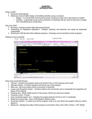
  • 1. 1 CHAPTER I INTRODUCTION What is CAD?  Computer Aided Design  Allows you to accomplish design and drafting activities using a computer. ◦ Design – is a broad field involving the process of making an idea into a real product or system. ◦ Drafting – is generally known as the production of drawings that are used to document a design from manufacturing or construction. Why Use CAD?  Accuracy - It stores numeric data with great precision.  Productivity for Repetitive Operations - Shaped, drawings and elements can easily be duplicated (copy/paste)  Sharing the CAD file with other software programs - Drawings can be imported to other programs. Getting to know AutoCAD Parts of the AutoCAD Window  Title bar - Contains the program name and the title of the current drawing and its path.  Standard toolbar - Contains standard commands use in the program.  Menu bar - Bar that contains all the commands in AutoCAD.  Layers and Properties toolbar - Contains buttons and commands use to manipulate the properties and layers of the drawing.  Drawing area - Blank middle section of the screen. Where you draw your shapes  Crosshair cursor - Pointer  User coordinate system icon - Indicates the positive direction for the X and Y coordinates  Model and Layout tabs - Use to shift between different views.  Command window - Is where you tell the program what to do and where the program tells you what’s going on.  Status bar - Displays the status of the program’s commands: Snap, Grid, Ortho, Otrack , LWT, Model
  • 2. 2 Drop-Down Menus  View - Contains tools for controlling the display of your drawing file.  Insert - Contains commands for placing drawings and images or parts of them inside other drawings.  Format - Contains commands for setting up general parameters for a new drawing.  Tools - Contains special tools for use while you are working on the current drawing.  Draw - Contains commands for displaying new objects (lines, circles) on the screen.  Dimension - Contains commands for dimensioning a drawing.  Modify - Contains commands for changing existing objects in the drawing  Window - Contains commands for displaying currently open windows and lists currently open drawing files. Command Entry  Methods of Entering Commands: ◦ Toolbars - Select the command by picking an icon from a toolbar ◦ Pull-down Menu - Select the command from a pull-down menu ◦ Screen (side) Menu - Select the command from the screen (side) menu. ◦ Keyboard - Type the command name, command alias or CTRL (accelerator) keys at the keyboard.  Using the Mouse ◦ Left button – PICK  Used to select commands or pick locations on the screen. ◦ Right button – Enter or shortcut Menu  This button either performs the same function as the enter key or produces a shortcut menu. ◦ Middle button or wheel – Pan / Zoom  Press and Drag – Pan the drawing about on the screen.  Wheel – zoom in or zoom out Function Keys  F1 – Help. Opens help window providing written explanation on commands and variables.  F2 – Flipscreen. Activates a text window showing the previous command line activity (command history)  F3 – Osnap Toggle. Turns the Osnap on or off.  F4 – Tablet. Turns Tabmode variable on or off.  F5 – Isoplane. Isometric Style Snap and Grid Setting, Toggles the cursor to dram on one of the isometric planes.  F6 – Coords. Toggles the coordinate display between cursor tracking mode and off.  F7 – Grid. Turns the grid on or off.  F8 – Ortho. Turns the ortho on or off.  F9 – Snap. Turns the snap on or off.  F10 – Polar. Turns the polar on or off.  F11 – Osnap Tracking. Turns the osnap tracking on or off.  F12 – Dyn. Turns the dynamic input on or off. Drawing Aid  SNAP (F9) ◦ Grid Snap – forces the cursor to snap to regular intervals (grid) ◦ Polar Snap – forces the cursor to snap regular intervals along angular lines.  GRID (F7) - Used as visual reference of units and lengths.  ORTHO (F8) - Lines are forced to an orthogonal alignment (only horizontal or vertical) when drawing.  Polar (F10) - Makes it easy to draw lines at regular angular increments, such as 30, 45 and 90 degrees.  OSNAP (F3, Object Snap)  OTRACK (F11)  DYN (F12) - A feature that helps you visualize and specify coordinates when drawing lines, arcs, circles and the like.
  • 3. 3 Basic Commands in AutoCAD Standard Toolbar Drawing Toolbar Modify Toolbar CHAPTER 2 BASIC COMMANDS TO GET STARTED Drawing Icons/Toolbars  Construction Lines - Lines that extend to infinity in one or both directions. It be used as references for creating other objects.  Polyline - An object composed of one or more connected line segments or circular arcs treated as a single object. Also called pline.  Polygon - Used to create closed polylines with between 3 and 1,024 equal-length sides.  Spline - A spline is a smooth curve that passes through or near a given set of points. You can control how closely the curve fits the points.  Ellipse - The shape of an ellipse is determined by two axes that define its length and width. The longer axis is called the major axis, and the shorter one is the minor axis.  Ellipse Arc  Point - Point objects are useful as nodes or reference geometry for object snaps and relative offsets.  Text
  • 4. 4 The Box Line Command  Line Commands o Draws a line between locations on existing lines, between geometric figures, or between points that you choose anywhere on the screen. o Designation of the points is either by clicking on the screen or entering coordinates (X and Y).  To use line command o Click line icon o Type the word “line” [enter] o Type the letter “l” [enter] Note: AutoCAD is not case sensitive Using Coordinates For 2D (Two-Dimensional) X and Y For 3D (Three-Dimensional) X, Y and Z Using Coordinates in Drawing Lines Relative Cartesian/Polar Coordinates  Uses relative X and Y coordinates.  Relies on a distance and an angle relative to the last point specified.  “@”  lets AutoCAD knows you’re using relative coordinates. Absolute Cartesian/Polar Coordinates  Uses the absolute distances in the Cartesian plane.
  • 5. 5 Drawing Box Using Cartesian Coordinates  Erase everything  Click erase icon or type word “erase” or “e”  Type “all” and  Click line icon (“line” or “l”)  Specify the first point, type 3,3  Type @6,0  Type @0,5  Type @-6,0  Type c Note: “C” stands for close, connects the last point of the line to the first point. Using Relative Polar Coordinates  Erase everything.  Start line command.  Type 3,3  Type @6<0  Type @5<90  Type @6<180  Type c Offset Command - Creates a new object whose shape parallels the shape of a selected object. Offsetting a circle or an arc creates a larger or smaller circle or arc, depending on which side you specify for the offset. You can offset:  Lines  Arcs  Circles  Ellipses and elliptical arcs (resulting in an oval-shaped spline)  2D polylines  Construction lines (xlines) and rays  Splines Offset Commands Involves 3 steps 1. Setting the offset distance. 2. Picking the object to offset 3. Indication the offset direction Offsetting the Lines 1. Click Offset icon or type “offset” or “o”. 2. Specify the offset distance 0.5 [enter] 3. Place the pickbox on one of the lines and click. The selected line ghosts and the cursor changes back to crosshair, and the prompt changes to Specify point on side to offset: 4. Pick point somewhere inside the box. 5. Press enter to end the offset command. 6. Do the same to the other 3 lines.
  • 6. 6 Trimming of line You can trim objects so that they end precisely at boundary edges defined by other objects. For example, you can clean up the intersection of two walls smoothly by trimming. An object can be one of the cutting edges and one of the objects being trimmed. For example, in the illustrated light fixture, the circle is a cutting edge for the construction lines and is also being trimmed. When you trim several objects, the different selection methods can help you choose the current cutting edges and objects to trim. In the following example, the cutting edges are selected using crossing selection. You can trim objects to their nearest intersection with other objects. Instead of selecting cutting edges, you press ENTER. Then, when you select the objects to trim, the nearest displayed objects act as cutting edges. In this example, the walls are trimmed so that they intersect smoothly. Extend Command Extending operates the same way as trimming. You can extend objects so they end precisely at boundary edges defined by other objects. In this example, you extend the lines precisely to a circle, which is the boundary edge.
  • 7. 7 Fillet Command A fillet connects two objects with an arc that is tangent to the objects and has a specified radius. You can fillet: Arcs, Circles, Ellipses and elliptical arcs, Lines, Polylines, Rays, Splines, Xlines, 3D solids Set the Fillet Radius The fillet radius is the radius of the arc that connects filleted objects. Changing the fillet radius affects subsequent fillets. If you set the fillet radius to 0, filleted objects are trimmed or extended until they intersect, but no arc is created. Drawing the box. Step by step instruction: 1. Start with a new sheet or erase everything by clicking erase icon or type word “erase” or “e”. Type “all” and (enter) 2. Click line icon (or type “line” or “l”) (enter) 3. Specify the first point, type 3,3 (enter) 4. Type @6,0 (enter) 5. Type @0,5 (enter) 6. Type @-6,0 (enter) 7. Type c
  • 8. 8 8. Type zoom (enter) and a (enter) to enlarge the drawing and placed the drawing in the center of the screen 9. Click offset icon (or type “offset” or “o”) (enter) 10. For the offset distance type 0.5 (enter) 11. Click the topmost line, put the mouse pointer somewhere in the middle of the box, and then click. 12. Click the right line and click at the center 13. Click the bottom line and click at the center 14. Click the left line and click at the center 15. Press (enter) or Esc to stop the offset command 16. Click the fillet icon (or type “fillet” or “f”) (enter) 17. Click the top inner line and the right inner line 18. Click fillet icon again (or type “fillet” or “f”) (enter) 19. Click the right inner line and the bottom inner line 20. Click fillet icon again (or type “fillet” or “f”) (enter) 21. Click the bottom inner line and left inner line 22. Click the fillet icon again (or type “fillet” or “f”) (enter) 23. Click the left inner line and top inner line Note: you can press (enter) to repeat previous command
  • 9. 9 24. Click offset icon (or type “offset” or “o”) (enter) 25. Offset distance = 0.5 26. Click the inner right line, and click at the center of the box 27.  (enter) to end offset command 28. Click offset icon (or type “offset” or “o”) (enter) 29. Offset distance = 2.0 Note: you need to start a new offset command if you want to change the offset distance. 30. Click extend icon (or type “extend” or “ex”) (enter) 31. You will be asked for the boundary edges. Click the outer lower line. (enter) 32. Then click the two newly created line (the one created by using offset command) 33. Click trim icon (or type “trim” or “tr”) 34. You will be asked for the cutting edges, click the 2 lines you just extended and the 2 bottom lines. Press  35. You can start trimming or remove the unwanted lines in the drawing 36. Click the 2 bottom lines in the middle of the 2 vertical cutting edges
  • 10. 10 37. Click the 2 inner lines above the bottom lines CHAPTER 3 SETTING UP A DRAWING Drawing Units  Every object you create is measured in drawing units.  Before you start to draw, you must decide what one drawing unit will represent based on what you plan to draw.  Then you create your drawing at actual size with that convention.  For example, a distance of one drawing unit typically represents one millimeter, one centimeter, one inch, or one foot in real-world units. Setting the Drawing Units Choose Format  Units (Open Drawing Units Dialog Box) Linear Units › Architectural - This type of uses feet and inches with fractions. › Decimal - Uses decimal units that can represent any linear unit of measurement. › Engineering - Units are equivalent to Architectural units except that inches were displayed as decimals rather than fractions. › Fractional - Everything is in inches (centimeters) › Scientific - Uses Scientific Notation. Before trimming After trimming
  • 11. 11 Angular Units › Decimal - Uses 360 degrees in a circle. › Deg/Min/Sec - Uses traditional system for measuring angles. › Grads - Unit uses 400 grads in a circle › Radians - Uses 2 radians › Surveyor - Use bearings from north and south directions. Drawing Size Grid › The grid is a rectangular pattern of dots or lines that extend over the area you specify as the grid limits. Using the grid is similar to placing a sheet of grid paper under a drawing. The grid helps you align objects and visualize the distances between them. The grid is not plotted. › Snap mode restricts the movement of the crosshairs to intervals that you define. When Snap mode is on, the cursor seems to adhere, or "snap," to an invisible rectangular grid. Snap is useful for specifying precise points with the arrow keys or the pointing device. › Grid mode and Snap mode are independent but are often turned on at the same time. › To turn on the grid, press F7. Drawing Limits › The user-defined rectangular boundary of the drawing area covered by dots when the grid is turned on. › Default lower point is 0,0 Note: Symbols: ‘  feet “  inch Steps in saving AutoCAD drawings. 1. Click save icon or go to file, then choose save (or save as) 2. This will open the Save as Dialog box.
  • 12. 12 3. In the Save in drop down list, choose the drive and/or folder where you want to save your drawing. 4. If you want to create a new folder, click the New Folder icon or press Alt+5. 5. In the filename textbox, type in the name of the file. 6. If you want to change the format of the drawing (compatibility purposes), choose from the drop down menus of Files of Type. 7. Click save. 8. The name of your file is now visible at the upper left corner of the AutoCAD window. CHAPTER 4 DRAWING STRATEGIES 1 CABIN A-1 Basic Floor Plan of the Cabin Bedroom
  • 13. 13 In order to draw the figure above it is recommended that you divide the drawing in different divisions. Divisions: D1: Laying out of the Exterior Wall Lines D2: Laying out of the Interior Wall Lines D3: Cutting Openings in the Walls D4: Drawing of Doors D5: Drawing of Sliding Door D1. Laying out of the Exterior Wall Lines. Step 1. Setup drawing parameters: › Length  Type  Architectural  Precision  0’-0 1/16” › Angle  Type  Decimal Degree  Precision  0.00 › Units to Scale  inches › Drawing Limits  Lower left  0,0  Upper right  60’,40’ › Filename: Cabin_A › Filetype: AutoCAD 2007 Drawing
  • 14. 14 Step 2. Make the outside box with the dimension of 25’ (feet) x 16’ (feet) a. Start line command b. First point, type: 3,3 c. Next point: @25’,0 d. Next point: @0, 16’ e. Next point: @-25’,0 f. Type “c” Step 3. Make the inner box with the offset distance of 6” (inches) a. Start the offset command b. Offset distance is 6” c. Click the top line, then click the center of the box d. Click the right line, then click the center of the box e. Click the left line and click the center of the box f. Click the bottom line and click the center of the box Step 4. Remove the intersecting line by using fillet. a. Start fillet command by clicking the fillet icon or by typing “f” b. Click the upper line, then click the right line c. Start the fillet command again by either clicking the icon, typing “f” or pressing the enter key ( ) d. Click the right line and the bottom line e. Start the fillet command again f. Click the bottom line and the left line g. Start the fillet command again h. Click the left line and the upper line 1.1. D2: Laying out of the Interior Wall Lines
  • 15. 15 Step 1. Make the internal wall divisions by using offset, fillet and trim commands. (Bedroom) a. Start offset command b. Offset distance is 9’4”’ c. Click the inside line of the left exterior wall d. Click somewhere in the center of the box e. To stop offset command, press f. Start offset command again to change the offset distance to 4” g. Click the new line h. Click somewhere in the right side of the line i. Stop the current offset command j. Start offset command again k. Offset distance is 6’6” l. Click the inside line of the upper exterior wall m. Click somewhere in the middle of the box n. End and restart offset command o. Offset distance is 4” p. Click the newly formed line, and click somewhere under the new line. q. End offset command
  • 16. 16 r. Start fillet command s. Click the two outer lines to joined them t. Start fillet command again, and click the two inner lines. u. To remove the intersecting lines in the drawing, zoom and trim commands will be use.  Zoom  Allows user to increase or decrease the magnification of the view of the current drawing in the drawing area.  Types of Zoom: o Zoom to Magnify a Specified Rectangular Area – allows the user to quickly zoom on a rectangular area of the drawing by specifying two diagonal corners of the area of interest. o Zoom in Real Time - zoom dynamically by moving your pointing device up or down. The scroll button of the mouse can also be used to zoom in and out of the drawing. o Zoom to View All Objects in the Drawing  ZOOM Extents displays a view with the largest possible magnification that includes all of the objects in the drawing. This view includes objects on layers that are turned off but does not include objects on frozen layers.  ZOOM All displays either the user-defined grid limits or the drawing extents, whichever view is larger.
  • 17. 17 i. Click zoom window icon or type “z” then create a small rectangle/window in the area to be magnified. j. Click trim icon or type “tr” . For cutting edges, click the two interior wall lines and press . v. For the part to be trimmed, click the inside exterior wall line between the two interior wall lines. And press . w. To view the entire drawing, type “z” (enter), then “a” (enter). x. Clean the lower area of the drawing using zoom and trim. Step 2. Make the internal wall divisions by using offset, fillet and trim commands. (Bathroom). a. Start offset command b. Offset distance is 6’ c. Click the inside line of the left exterior wall d. Click somewhere in the center of the box
  • 18. 18 e. To stop offset command, press f. Start offset command again to change the offset distance g. Offset distance is 4” h. Click the newly offsetted line i. Click somewhere in the right side of the line j. Stop the current offset command k. With the use of zoom and trim, remove the short portion of the intersected wall lines between the two new wall lines.
  • 19. 19 ACTIVITY Drawing parameters: › Length  Type  Architectural  Precision  0’-0 1/16” › Angle  Type  Decimal Degree  Precision  0.00 › Units to Scale  inches › Drawing Limits  Lower left  0,0  Upper right  60’,60’ › Filename: Act 4.1 › Filetype: AutoCAD 2007 Drawing
  • 20. 20 D3: Cutting Openings in the Walls Step 1. Creating the opening for the front and back doors (Exterior doors). a. Click the offset icon, then type 6” to set the distance. b. Click the two innermost interior lines and offset it to the center. c. End and restart the offset commands, set the offset distance to 3’. And offset the new lines. d. Extend the new lines through the external walls. e. Trim the lines to create the opening.
  • 21. 21 Step 2. Cutting the Interior Openings. a. Start offset command and set the distance to 6”. b. Offset the lines with the “x” in the figure below. c. Restart the offset command and set the distance to 2’6”. d. Offset the new lines. e. Use extend and trim to remove the lines and create the opening. Step 3. The 7’ Opening. a. Offset a wall line by 12”. b. Offset the new line by 7’. c. Extend both new lines through the walls. d. Trim the new lines and the wall lines to create the opening.
  • 22. 22 ACTIVITY Continue previous activity and create the openings for your drawing. Upper Part of the Office Lower Part of the Office
  • 23. 23 D4: Creating the Doors Object Snaps.  Enables the user to snap to existing object endpoints, midpoints, centers, intersections and etc.  Object snaps must be active for the user to snap to desired objects.  Object Snap Modes: o Center - finds the center of a circle, arc, donut or any circular object. o Endpoint - snaps to the endpoint of a Line, Pline, Spline, or Arc
  • 24. 24 o Insert – locates the insertion point of Text or a Block. o Intersection – snaps to the intersection of any two objects. o Midpoint - snaps to the point in the middle or halfway between two endpoints. o Nearest – locates the point on the object which is nearest to the cursor. o Node – snap to a point object. o Perpendicular – snaps to the perpendicular to the selected object.
  • 25. 25 o Quadrant – snaps to the 0°, 90°, 180° or 270° of a circle. o Tangent – snaps to a tangent point of a circle or an arc. Rotate - Enables user to rotate an object/figure to a certain angle. Copy - Enables the user to create duplicates of objects at a specific distance and direction from the original object/s.
  • 26. 26 Mirror  Enables user to create a mirror image of a selected existing object/s. Original figure can be deleted or retained.  Creates symmetrical objects because you can quickly draw half the object and then mirror it instead of drawing the entire object. Step 1. Creating the front door. a. Check the status bar at the bottom of the screen and make sure the Model button is pressed and all other buttons are pressed off. b. Click tools, then drafting settings to open the drafting settings dialog box. c. Click the Object Snap tab. d. Make sure the following boxes are checked:  Object Snap On  Endpoint  Midpoint e. Click ok. f. Click the zoom window button and pick two points to form a window around the front doorway opening for a close up view of the drawing.
  • 27. 27 g. To draw the door, click the rectangle icon on the toolbar. h. Move the cursor near the upper end of the opening, when the cursor gets very close to the line, a colored square appears at the nearest endpoint. i. Move the cursor closure to the colored box near the upper left corner of the opening. j. Click on the endpoint. k. For the next point of the rectangle, type @3’,-1.5 l. To create an open door, the newly created rectangle needs to be rotated. m. Click the rotate icon or type “ro” n. When prompted to select the object to rotate, click the door and press . o. When asked for the base point, move the cursor near the upper-left corner of the door. When the colored square is displayed, click the endpoint. p. Type 90 when prompted for the rotation angle.
  • 28. 28 q. To make the swing of the door, the arc command will be used.  Swing – shows the path that the outer edge of the door takes when it swings open. r. Choose Draw  Arc or click the Arc icon in the drawing toolbar. s. The arc needs 3 points inorder to be formed. 1st point: 2nd point: 3rd point: t. Front door is completed.
  • 29. 29 Step 2. Creating the back door. Since the front door and the back door has the same size (dimensions). The front door can be duplicated and placed on the opening for the back door. And the figure can be flipped to give the door swing the correct movement. a. Click the copy button or type “co” b. When asked to select the object/s to be copied, click the door and the swing. c. For the base point of the figure click the point that joins the door and the wall. d. Attach the copied door to the lower left point of the back door opening. e. Click to end the copy command. f. The door is oriented the wrong way. In order to fix the orientation, the figure needs to be flipped by 180° with the use of mirror command. g. Choose zoom window icon and create a window around the back door opening. h. Start mirror command or type “mi” i. Select the back door and swing and press
  • 30. 30 j. For the first point of the mirror lines, pick the hinge point of the door. k. For the second point, type @3’,<180 l. When asked to delete source object, type “N” m. The door now is oriented properly. Step 3. Interior Doors. a. Use rectangle command to draw the door from the hinge to a point @1.5’,-2’6. b. Rotate the door around the hinge point to an open position. c. Use arc command to draw the swing of the door. d. Use copy command to copy the door and swing to the other opening. e. Use mirror to flip the door to the proper orientation. n. To see the whole drawing, type “z” “a”
  • 31. 31 Draw the doors on your previous activity
  • 32. 32 D5. Drawing of Sliding Door. a. Click the zoom window icon and make a zoom window closely around the 7’ opening. b. Click tools, then drafting settings to open the drafting settings dialog box. c. Click the Object Snap tab, and check the perpendicular check box. d. Offset each jamb line 2” into the doorway opening. (Jamb line - The vertical side of any opening, as a door or fireplace) e. Start line command, and draw a line from the midpoint of the upper door opening to the lower door opening. f. Offset the new line created by 1.5” on both sides. g. Turn on the Ortho F8 by pressing F8. h. Start the line command and draw a horizontal line through the three vertical lines.
  • 33. 33 i. Start the offset command. With the distance of 1”, offset the new lines above and below itself. j. Start the trim command, use the two outer horizontal lines as cutting edges and cut the two outside vertical lines. k. Restart the trim command, pick the point above the right of the opening and move the cursor to a point below and to the left of the opening forming a window with dashed lines. l. Everything inside the window will be selected. Press m. Cut the following lines.
  • 34. 34 n. Start the line command, and make a line from the midpoint of the two small rectangles going to the center.
  • 35. 35 Draw the sliding door on previous activity. Use the same dimensions as the once on your cabin.
  • 36. 36 CHAPTER 5 DRAWING STRATEGIES 2 CABIN A-2 Cabin with steps, thresholds, balcony, kitchen and bathroom In order to draw the figure above it is recommended that you divide the drawing in different divisions. Divisions: D1: Drawing the steps and thresholds D2: Draying the balcony D3: Drawing the kitchen D4: Drawing the bathroom Cabin with steps and thresholds
  • 37. 37 D1. Drawing the steps and thresholds. Step 1.Drawing the front step. a. Use zoom command to magnify the front step. b. Start line command and activate the endpoint osnap. Pick a point at the lower end of the left jamb line. c. Right click the polar button on the status bar located at the bottom of the screen. Open the Drafting and settings dialog box. Make sure that the polar tracking tab is active. d. At the polar angle settings, check if the incremental angle is set to 90. e. Hold the cursor so that it is below the first point you have picked. DO NOT PICK A POINT YET. A dashed line called a temporary alignment path will be displayed that will identify the polar path. f. While the alignment path and tool tip are visible, type 2’ . Direct Entry – method of entering the distance directly, using the cursor as the guide to the direction of the line/figure. g. Press to end the line command. h. Start offset command.
  • 38. 38 i. Type 1’6” for the offset distance. j. Offset the line to the left. k. Press twice to stop and restart the offset command. l. Type 6’ for the offset distance. m. Offset the new line to the right. n. Erase the original line. o. Draw a line that connects the lower endpoints of the two new line. Step 2.Drawing the back step. a. Zoom into the back door area. b. Start the line command. c. Pick the upper end of the jamb line. d. Hold the cursor to the left of the temporary tracking point. e. Type 12 for the distance of the line. f. Hold the cursor directly above the end point of the first line.
  • 39. 39 g. Type 2’ for the distance of the second line. h. Hold the cursor directly to the right of the endpoint of the second line. i. Type 5’ for the distance of the third line. j. Select perpendicular osnap from the object snap toolbar. k. Move the cursor to the outside wall line and click the mouse button. l. End the line command. Step 3. Drawing of the thresholds. a. Zoom in to any door opening. Note: Thresholds is a strip of wood, metal, or stone forming the bottom of a doorway and crossed in entering a house. b. Start line command. Make sure that the temporary tracking and endpoint osnap are turned on.
  • 40. 40 c. Click the outside end point of the jamb lines. d. Move the cursor along the wall lines (lines must be straight). e. Type 3” for the distance of the first line. f. Move the cursor away from the wall line, make sure that the line is kept straight. g. Type 2” for the distance of the second line. h. Press two times to end and restart line command. i. Click the outside line of the other jamb line of the same opening. j. Move the cursor along the wall lines. k. Type 3” for the distance of the third line.
  • 41. 41 l. Move the cursor away from the wall line. m. Type 2” for the distance of the fourth line. n. Press two times to end and restart line command. o. Connect the two endpoints of the newly created lines. Draw the thresholds for the other two main doors on your office drawings. Same dimensions applies for the other thresholds.