SlideShare ist ein Scribd-Unternehmen logo
1 von 17
CONTROL CONSOLES
Coiled tubing control consoles may vary in appearance from one unit to another because of the age
and type of the unit. Check that the console control functions are standardized and meet the
requirements outlined in the design specifications for coiled tubing unit control consoles.

6 0 K Con t r o l Cons o l e
The oper a t or can control and monitor all of the CTU’s functions (including the
stripp e r and the BOP) from the control console. Figure 1 shows the seve n
major are a s of the control console pan el.
Figure 1—Control console panel

The consol e oper a t or can control the following functions:
• engin e start
• engin e stop
• engin e spe e d
• engin e eme r g e n c y kill
• injector- gripper pres s ur e
• injector- gripper direction
(grip or retra c t)
• reel direction
• reel holding brake
• reel tension (pre s s u r e )
• levelwind override direction
• levelwind boo m direction
• injector holding brake
• injector direction (in or out)
• injector pres s u r e
• injector- mot or displac e m e n t
• stripp e r position (strip or retr a c t)
• stripp e r pres s ur e
• stripp e r hand- pump pres s u r e
• auxiliary BOP ra ms (thre e)
• BOP blind ra m
• BOP cutt e r ra m
• BOP tubing ra m
• BOP slips ra m
• accu m ul a t or pre s s ur e
The consol e oper a t or can monitor the following para m e t e r s :
• wellhe a d pres s ur e
• tubing pres s ur e
• weight indicat or
• console oper a tin g pres s ur e
• console pilot control pres s ur e
• power- pack a g e engine tacho m e t e r
• injector grippe r pres s ur e
• reel pump pres s ur e
• injector pump pres s ur e
• injector pump torqu e / s p e e d pres s ur e
• strippe r hydr a ulic pres s ur e
• strippe r hydr a ulic supply (oper a tin g) pres s u r e
• BOP hydr a ulic supply pres s u r e
• alter n a t or char ging for both the power pack
and the hous e
The consol e cont ains ma n u a l hydr a ulic pu mp s that can supply e me r g e n c y
pres s u r e for the control of vital functions if the main pump fails. All
direction al
control valves are close d when the knob or lever is cent e r e d .

Engine Control
The engin e controls are locat e d in the uppe r left are a of the control console
pan el
(Figur e 1) The engine control are a of the control console pan el is
shown in Figure 2.
Figure 2—Engine control area of the console
The START , s TOP , and EMERGENCY KILL push button s start and stop the engine . All
engin e controls are pne u m a t i c ally oper a t e d . The AIR THROTTLE regula ting valve
controls the engine spe e d. Clockwis e rota tion of the valve incre a s e s engin e
spe e d. The tacho m e t e r at the far left side of the control consol e pan el shows
the
engin e spe e d .
Note If you use the EMERGENCY KILL, you mus t res e t the kill cylinder
before the engin e will rest a r t.
The controls for the outsid e flood lights, the air condition e r, and the hea t e r
are
also in this are a . Undern e a t h the tacho m e t e r controls are the volt me t e r s
desig- nat e d
for both the power pack and the hous e alter n a t o r s .

Primary Injector
The PRIMARY INJECTOR or “gripp er” controls are locat e d on the left side of the
consol e (Figur e 1). The grippe r control are a of the control- console
pan el is shown in Figure 3.
Figure 3 – Primar y Injector or Gripper control are a of the consol e

The GRIPPER POSITION lever controls the eng a g e m e n t of the grip cylinde r s and the
gripper blocks. The lever has two positions: GRIP and RETRACT. Once it is place d
in the require d position, the lever locks in place. Positioning the gripper
position
lever to the GRIP or RETRACT position direct s hydr a ulic pres s u r e to the linearbe a m
grip cylinder s . In the grip position, applied pres s ur e to the grip cylinder s
caus e s
the linear be a m s to exert pres s u r e on the tubing OD throug h the grippe r
blocks.
Sufficient pres s ur e prev e n t s the tubing from sliding in the gripper blocks as
the
tubing is inject e d into or re mov e d from the well.
Turning the GRIPPER PRESSURE ADJUST knob clockwis e incre a s e s the grippe r
pres s u r e . The gripper pres s ur e mus t be adjust e d to a level high enoug h to
preve n t slippa g e of the tubing at oper a ting loads.
Although pres s ur e can be incre a s e d from the consol e, the oper a t or mus t first
adjus t the pres s ur e to the require d value and the n open the blee d valve at
the
injector' s accu m ul a t or until the pres s ur e is stabilize d at the requir e d value.
This
proc e s s is nec e s s a r y bec a u s e of a safet y pilot- oper a t e d check- valve that
preve n t s
the loss of be a m pres s u r e whe n hydr a ulic pres s ur e is lost.
The OPEN FOR GRIPPER HAND PUMP valve should be close d und er nor mal oper a tin g
conditions. If, howev e r, hydr a ulic pres s u r e is lost, the accu m ul a t or on the
injector should hold grippe r pres s u r e . If this accu m ul a t or pres s ur e start s
drop- ping,
ope n the OPEN FOR GRIPPER HAND PUMP valve by turning the valve count e r- clockwis e.
Then use the ma n u al hand pu mp locat e d und er the console to hold
pres s u r e on the gripper blocks until the BOP can be activat e d or until the
tubing
is sta ble.
To maint ain control of the coiled tubing workstring, you mus t apply sufficient
linear be a m pres s u r e to the tubing to prev e n t slippa g e betw e e n the tubing
and the
gripper blocks. The reco m m e n d e d linear be a m pres s u r e for a given hoisting
load
for the 60k injector is define d by the following equ a tion s:
p = 200 psi (whe n Q < 10,00 0 lb)
p = Q ÷ 50 psi (whe n Q > 10,000 lb)
wher e p is the hydr a ulic pres s u r e (psi) applied to the linear be a m cylinder s
(indica t e d by the oper a t or control cons ol e gaug e labele d GRIPPER PRESSURE ) and
Q
is the axial hoisting load (lb) on the tubing.

Note Thes e reco m m e n d e d value s are bas e d on cons e rv a tiv e ass u m p - tions.
Many factor s affect the gripping efficiency of the gripper
blocks. Therefor e , differe n t be a m pres s u r e s ma y be use d bas e d
on the conditions pres e n t .
Exces sive gripper pres s ur e plac e s unn e c e s s a r y stre s s on the tubing and can
result
in decr e a s e d tubing life and da ma g e to the tubing. See the Gripper Block for
Coiled Tubing Injectors Manual (Part No. 70.51 1 4 0) for reco m m e n d e d gripper
pres s u r e s for various tubing sizes and wall thickne s s e s .
The GRIPPER PRESSURE gaug e indicat e s the pres s ur e applied to the grippe r.

Reel Controls
The reel and levelwind controls are locat e d in the REEL are a at the botto m of
the
control consol e (Figur e 1). The reel control are a of the control- consol e
pan el is shown in Figure 4
Figure 4—Reel control area of the console
The REEL TORQUE LEVER controls the direction and winding force of the tubing
reel. The lever oper a t e s the direction al valve to the main reel mot or. The
SLACK

(spool- off) position caus e s the reel to rota t e in a direction that unwinds the
coiled tubing.
Cauti o n Car e sh o u l d be tak e n to pre v e n t th e tubi n g fro m un w r a p pin g
an d birdn e s t i n g w h e n th e re e l is in th e sla c k mo d e .
Unwr a p p i n g coul d re s u l t in tubi n g da m a g e .
The TENSION (spool- on) position caus e s the reel to rota t e in a direction that
rewinds the coiled tubing. During nor mal oper a tion s , the reel is kept in the
TENSION position all the time to ens ur e that the coiled tubing re mai n s tightly
wound on the reel.
The MAX PRESS ADJUST knob controls the hydr a ulic pres s u r e to the reel drive
mot or. This knob is conn e c t e d to the high- and low- set pres s ur e- relief valves
locat e d on the reel’s power pack ma nifold block. Turning the knob clockwis e
incre a s e s the torqu e of the reel drive mot or. Monitor the reel pres s u r e during
the
job and adjust it as nec e s s a r y to maint ain a consist e n t coiled tubing wrap on
the
reel.
The PUMP pres s u r e gaug e indicat e s the reel pu mp pres s u r e whe n the REEL TORQUE
valve is in the TENSION position.
The HOLDING BRAKE knob set s and rele a s e s the brake on the reel. The reel
holding
brake is locat e d inside the reel plan e t a r y ge ar box. The brake is a fail-safe,
disc- type,
spring- set/pr e s s u r e - rele a s e brak e. In the SET position, the hydr a ulic pres- sure
is du mp e d off the brak e piston, and the springs set the brak e. In the RELEASE
position, pre s s ur e is applied to the brak e piston and the brak e is rele a s e d to
allow
reel rotation.
Cauti o n Do no t s e t th e re e l hol di n g brak e w hil e th e re e l is turni n g .
The re e l hol di n g brak e is a parki n g brak e onl y .
Occasion al interru ption of the auto- levelwind ma y be nec e s s a r y to ens ur e
that
the tubing wraps are unifor m. The LEVELWIND OVERRIDE knob allows the oper a t or
to interru pt the auto m a ti c levelwind me c h a ni s m on the reel to adjus t the
wraps of
tubing. The knob is spring- bias e d to the cent e r (neutr al) position. When the
knob
is relea s e d , it stops the override function and re- eng a g e s the auto m a t ic
levelwind.
The LEVELWIND BOOM knob allows the levelwind tubing guide to be raise d ( UP ) or
lower e d ( DOWN ) so that the correct relations hi p betw e e n the reel and the
injector
tubing guide can be ma d e for optimu m oper a tion. The valve is also springbias e d
to the cent e r position.

Injector Controls
The injector pu mp and motor controls are locat e d at the botto m cent e r of the
consol e (Figur e 1). The injector control are a of the control console
pan el is shown in Figure 4.
Figure 4 –Injector control area of the console

The INJECTOR SPEED lever (Munson- Tyson valve) controls the spe e d and direction
of the injector. Specifically, it direct s pilot pres s ur e to the injector direction al
control, which both est a blish e s the direction of the injector and functions as a
flow- control valve that controls the a mo u n t of fluid to the motor s . The
injector
spe e d is controlled relative to how far from the cent e r position the lever is
place d. The injector is station a r y when the lever is cent e r e d , and the injector
is at
full spe e d when the lever is positione d in either of the extre m e positions.
The MAX PRESS ADJUST knob controls the hydr a ulic pres s u r e at the injector drive
mot or s. The knob oper a t e s by venting the main relief valve on the power
pack a g e’ s injector ma nifold. Turning the MAX PRESS ADJUST knob clockwis e
incre a s e s the power of the injector mot or s. The MAX PRESS ADJUST knob should be
adjus t e d to the mini mu m a mo u n t of pres s ur e nec e s s a r y to overco m e the
load- induc e d
resist a n c e .
The PUMP pres s u r e gaug e indicat e s the injector mot or pres s ur e regar dl e s s of
the
direction of rota tion. The gaug e also acts as a spar e weight indicator by
taking
the pres s u r e shown and multiplying by a factor of 12.
Note The weight indicator is a mor e accur a t e device for me a s u ri ng the
actu al injector forces.
The LOW SPEED / HI TORQUE / VAR knob allows the oper a t or to select the injector
mot or’s mod e of oper a tion. In the LOW SPEED / HI TORQUE mod e , the motor s oper a t e
at ma xi mu m displac e m e n t (low spe e d) for maxi mu m torqu e . In the VAR (variable)
mod e , the oper a t or can cha ng e the mot or displac e m e n t , and ther efor e,
affect the injector motor spe e d and torqu e in speci al applications .

Note When the injector is in variabl e mod e , the backpr e s s u r e on the
syst e m can caus e the injector spe e d to cha ng e . For exa m pl e ,
oper a ti ng the levelwind override caus e s the return pres s u r e to
incre a s e ; the incre a s e in retur n pres s u r e caus e s the injector
spe e d control pres s u r e to incre a s e , which caus e s the injector
spe e d to incre a s e .
The ADJUST knob to the right of the LOW SPEED / HI TORQUE / VAR knob controls the
spe e d and torqu e of the motor s in the VAR mod e . Clockwis e rota tion of the
knob
incre a s e s mot or spe e d and caus e s a corre s p o n di n g decr e a s e in availabl e
torqu e .
The pres s u r e gaug e next to the ADJUST knob indicat e s the injector mot or
control
pres s u r e .
The HOLDING BRAKE knob controls the injector holding brake s inside the plan e t a r y
ge ar boxe s that drive the injector. The brak e s are fail-safe, disc- type, springset/
pres s u r e- relea s e brake s . In the SET position, the hydr a ulic pres s u r e is
re mov e d
from the brake piston, and the springs set the brake . In the RELEASE position,
pres s u r e is applied to the brak e piston, and the brake is rele a s e d to allow
rotation
of the motor s .

BOP Controls
The valves and gaug e s controlling and displa ying the oper a tin g conditions of
the
BOPs are locat e d on the right side of the console. (See Figure 1) The
BOP control are a of the control cons ol e is shown in Figure 5.
Figure 5—BOP control area of the console
The BLIND, CUTTER , SLIPS , and TUBING levers control the ra ms on the qua d blowout
preve n t e r . The thre e spar e levers allow the oper a t or to control additional
safet y
BOPs. For all BOP ra ms , the control- valve levers are locke d in both the open
and
close position to prev e n t inadve r t e n t selection of either mod e . The BOPs are
nor mally eng a g e d whe n the tubing is station a r y. Closing the BOP ra ms while
running tubing can interfer e with tubing oper a tion s and da m a g e the tubing.
Dyna mic well- pres s ur e control is maint ain e d with the strippe r. To activat e
the BOP
ra ms , disen g a g e the locks, place the valve in the CLOSE position, and eng a g e
the
locks. To retra c t the ra ms , plac e the valve in the OPEN position.

If a syst e m hydr a ulic failure occur s, a check valve on the supply side of the
BOP
control ma nifold isolat e s the BOP controls. The hous e’s accu m ul a t or pack a g e
can
supply power to oper a t e the BOPs if the main syst e m pre s s ur e is lost. A hand
pu mp is also available as a final e me r g e n c y supply.
The SUPPLY pres s u r e gaug e indicat e s the hydr a ulic pre s s ur e available for
oper a t- ing
the BOPs. The gaug e doe s not indicat e the pres s u r e available from the
accu m ul a t or s .
In the eve nt of power loss from the power pack a g e , the accu m ul a t or s store
ener g y in the form of fluid pres s ur e . The accu m ul a t or s store enoug h ener g y
to
close all BOP ra ms 1.5 time s or to close, open, and close all the ra ms unde r
“worst cas e ” conditions.
The OPEN FOR BOP HAND PUMP valve should be close d unde r nor m al oper a ti ng
conditions. If hydr a ulic power is lost, the accu m ul a t or s should supply power
to
activa t e the BOPs. If, howe v e r , accu m ul a t or pres s ur e is lost, open the OPEN FOR
BOP HAND PUMP valve by turning the valve count e r clockwis e . To activat e the BOP,
eng a g e the BOP ra m knob and use the ma n u a l hand pump.
The ACCUMULATOR lever control rele a s e s pres s ur e stor e d in the accu m ul a t o r s
after
a job. All pres s u r e should be relea s e d befor e any hos e s are disconn e c t e d .
Stripper Controls
The valves and gaug e s controlling and displa ying the oper a tin g conditions of
the
stripp e r are locat e d at the lower right side of the consol e (Figure 1).
The stripp e r controls are a of the control consol e is shown in Figure 6.
Figure 6—Stripper control area of the console

The STRIPPER POSITION lever direct s hydr a ulic pres s u r e to the strippe r. Moving the
lever to the STRIP position applies pres s ur e to the port which squ e e z e s the
stripp e r
aroun d the tubing. This action provide s a seal aroun d the tubing to control
wellhe a d pres s ur e . The RETRACT position re mov e s pres s ur e from the stripp e r.
The STRIPPER PRESSURE ADJUST knob controls the a mo u n t of pres s u r e (sque e z e )
place d on the tubing. Turning the knob clockwis e incre a s e s the pres s ur e .
The HYDRAULIC SUPPLY pres s u r e gaug e indicat e s the pres s u r e available for
oper a ti ng
the stripp e r.
The STRIPPER PRESSURE gaug e indicat e s the pres s ur e being applied to the strippe r.
The OPEN FOR STRIPPER HAND PUMP valve should be close d und er nor mal oper a tin g
conditions. If, howev e r, hydr a ulic pres s u r e is lost, ope n the OPEN FOR STRIPPER
HAND PUMP valve by turning the knob count e r clockwis e . Make sure that the
STRIPPER POSITION valve is in the correct position and use the hand pu mp locat e d
und er the console.
To rele a s e the hand pump pres s ur e to the stripp e r, open the valve labele d
STRIP - PER
DUMP . The STRIPPER DUMP valve can also be use d to reduc e the strippe r
pres s u r e without moving the STRIPPER POSITION lever into its RETRACT position.
Miscellaneous Instrumen ts
Miscellan e o u s gaug e s and instru m e n t s are locat e d in the upp er cent e r, upp er
left,
and uppe r right of the control console pan el (Figure 1). Thes e are a s of the
control consol e pan el are shown in figure 7.
Figure 7 – Miscellaneous instruments area of the control console.

.
The CONSOLE PRESSURE gaug e indicat e s the oper a tin g pres s ur e of the main
hydr a ulic
syst e m.
The PILOT PRESSURE gaug e indicat e s the console pres s ur e provide d (500 psi or
3400 kPa) to oper a t e other cons ol e valve s.
The WELLHEAD PRESSURE gaug e indicat e s the wellhe a d pres s ur e . The gaug e is
isolat e d from the well fluids by a pres s ur e deboos t e r .
The TUBING PRESSURE gaug e indicat e s the pres s u r e on the tubing. The gaug e is
isolat e d from the well fluids by a pres s ur e deboos t e r .

Cauti o n The WELLHEAD PRESSURE ga u g e and th e TUBING PRESSURE ga u g e
ar e sp e c i a l ga u g e s wit h a 1:4 s e n s i n g - to- indi c a t i n g rati o . If
repl a c e d , th e s e ga u g e s mu s t be re pl a c e d wit h ide n t i c a l
ga u g e s . Failur e to do so will re s ul t in pr e s s u r e re a d i n g s tha t
ar e onl y 25% of th e ac t u a l w ell h e a d or tubi n g pr e s s u r e .
The digital and analog weight indicat or s indicat e the weight being suppor t e d
by
the load pins locat e d at the botto m of the injector. If prope rly “zeroe d, ” the s e
weight indicator s will indicat e the tubing loads, such as tubing weight and
snubbing force.
Both weight indicat or s are a part of the dat a acquisition syst e m (DAS). See
Section 10, 60k CTU Data- Acquisition Syst e m and the DAS ma n u a l s (Part No.
516.9 9 0 0 6 and Part No. 516.9 9 0 0 7) for mor e infor ma tio n.
3 0 K/ 3 8 K Con t r o l Con so l e
The operator can control and monitor all of the CTU’s functions from the control console. Figure 8 shows
the controls for a standard 30/38K coil tubing unit.

Figure 8 -
.25

D T I L C.
E AL O
SCA E F L
L UL
TP
Y
6 PA S
L CE
14 16

48

59 56 55

14

CO SO E
N L
PE
R SSUR
E

11 23

3

4

7

70

56 57 62

I J CO
NE TR
I
N
P E UR
R SS E

BA
EM
PE
R SSUR
E

69

14

IJCO
NE T R
OT
U
PE
R SSUR
E

B
OP
PE
R SSUR
E

ST I P R
RP E
PE
R SSUR
E

C AN
HI
OL R
IE

21
CO SOL
N E
LG T
I HS

BA
EM
PE
R SSUR
E
A J ST
DU

LG T
I HS

HG
IH
OF
F
LW
O
H AE
ETR

C AE
RN

48

A
/C

WL ED
E HA
L
PE
R SSUR
E

IJCO
NE T R
I
N

I J CO
NE TR
A J ST
DU

T BN
UI G
PE
R SSUR
E

OT
U

HR
ON

73

R E MT R
EL OO
PE
R SSUR
E
R E A JU
E L D ST

80

HG
IH

O
N

D P
UM

RE
EL

C

I
N
LW
O

LA
OD

OT
U

O
N

D P
UM
LA
OD

LA
OD

ST P
O
AR
I
PE
R SSUR
E

O
N
OF
F

O
N
OF
F

DM
UP
OF
F

OF
F
AR
I
R G A OR
E UL T

63 46

16 14

PM B
UP

AX
U
BA
EM

AX
U
B
OP

P PC
UM

31

31

AX
U
ST I P R
RP E

31

63 46

63 67

73

6
C
SE CU D T I
E T E AL
F RH N L S
O A DE

80

CU H N L S A D
T A DE N
T R A 1/2 - 13N
HE D
C

F

1.00
6.50

CU H N L S A D
T A DE N
T R A 1/2 - 13N
HE D
C

F

F

1.00
5.50

56 59 8

15
G
SE D T I
E E AL

F

CU H N L S A D
T A DE N
T R A 1/2 - 13N
HED
C

1.00

7.00

1.00

D
S

12- 0993

LH
J

_

F

4.50

H N L CUT O F D T I
A DE
F E AL

The console operator can control the following functions:
- engine start
- engine stop
- engine speed
- engine emergency kill
- injector gripper pressure
- injector gripper direction
- reel direction
- reel tension
- levelwind override direction
- injector direction(in or out)
- injector speed
- injector speed selector (high and low)
- stripper pressure
- stripper position
- BOP blind rams
- BOP cutter rams
- BOP tubing rams
- BOP slip rams
- auxiliary BOP rams (three)
- accumulator pressure
The console operator can monitor the following parameters:
- wellhead pressure

60

C

VE
IW

CU H N L S A D
T A DE N
T R A 1/2 - 13N
HE D
C

T R TL
HO T E
996 494- C
.15

ST I P R
RP E

55 56 59

G

EE
MR
KL
IL

L VL I D
EE W
N

OF
F
P PA
UM

22

DM
UP

ST R
AT

C

WI H I DCA O
EG T N I T R

BA
EM
PE
R SSUR
E

SP E
ED
C NRL
OTO

12- 2993

_

I ST N M
N L- I
SC
- H USE O E A O O - PRTR
COL T I G T AL R
I UBN R I E

3/8
I B 03- 03- 97
E

04 08

G 278.99742
-

tubing pressure
weight indicator
console operating pressure
injector gripper pressure
reel tension pressure
stripper hydraulic pressure
BOP supply pressure

The console contains manual hydraulic pumps that can supply emergency pressure for the control
of vital functions if the main pump fails. All directional control valves are closed when the knob or
lever is centered.
Engine Control
The START, STOP, and EMERGENCY KILL push buttons start and stop the engine. All engine
controls are pneumatically operated. The AIR THROTTLE regulating valve controls the engine
speed.
NOTE: If you use the EMERGENCY KILL, you must reset the kill switch on the power pack
before the engine will restart.
Injector Controls
Injector “In – Out” (Directional Control)
The injector direction is selected manually by positioning the lever to the “in” or “out” position.
This valve directs pilot pressure to the main directional control valve located on the power pack
and causes the valve to supply power to the injector drive motor ports.
Injector Adjust (Pressure Control)
The hydraulic pressure at the injector drive motors can be limited by adjusting the “injector
pressure control” valve. This valve is an adjustable relief valve that is connected by a hose to the
vent port on the main relief valve on the injector manifold block of the power pack. Turning the
injector adjustment valve knob counterclockwise causes the maximum pressure directed to the
injector motors to decrease. The adjusted pressure is the maximum pressure that is available to do
work. It is a good operating practice to adjust this control only high enough to overcome the load
induced resistance.
Injector ‘In – Out” Pressure Gauges
Two pressure gauges are mounted to the panel. One indicates the actual injector motor pressure in
the “in” direction and the other in the “out” direction. By monitoring the pressure on the gauge and
using the pressure factor found in the Injector section of the manual for the injector in use the
operator may calculate the approximate load.
NOTE: The weight indicator is a more accurate device for measuring the actual injector forces.
Beam Pressure (Injector Gripper Control)
Positioning the Beam Pressure control lever to the “on” or “off” position directs hydraulic
pressure to the linear beam cylinders. Application of pressure to the “on” cylinder ports causes
force to be exerted on the tubing OD by the linear beams. The force then generates the frictional
reaction force necessary to grip the tubing without sliding the gripper blocks on the tubing.
NOTE: This control should have a “Weevil lock” on it to keep it from being accidentally moved to
the “off” position while pipe is in the hole.
Beam Pressure Adjust (Injector Gripper Pressure Control)
The magnitude of the tubing frictional force is proportional to the amount of lateral force generated
by the gripper cylinders. The gripper pressure must be adjusted to a level high enough to prevent
slippage of the tubing at the operating loads. Too high a setting, however, places unnecessary
stresses on the tubing. Higher stresses cause the life of the tubing to decrease. High gripper
pressures also accelerate the wear rate on the injector chain components. A nominal setting of 1000
psi is recommended. Turning the knob clockwise increases the gripper pressure.
Gripper pressure is isolated at the injector by a pilot operated check valve. Reducing the pressure
on the house gauge will not reduce the pressure on the gripper beams. If the pressure needs to be
reduced there is a bleed off valve on the injector where this may be done. The operator must first
adjust the pressure to the required setting and then open the bleed off valve until the pressure is
stabilized. Extreme care should be taken when doing this.
NOTE: Refer to the “Gripper Block for Coiled Tubing Injectors Manual” (Part # 70.51140) for
recommended gripper pressures for various tubing sizes and wall thickness.
Aux. Beam
If hydraulic pressure is lost on the console, the beam pressure has a check valve, which isolates it
and allows pressure to be maintained on the beams. If this pressure starts dropping or needs to be
raised the Auxiliary Beam two-way valve should be switched from the “Off” position to the “On”
position. There is an emergency hand pump, located below the console, that will allow the operator
to supply pressure to the beams when this valve is in the “On” position
Beam Pressure gauge
The gauge “Beam Pressure” indicates the amount of hydraulic pressure that is being applied to the
gripper cylinders on the injector.
Speed Control “High – Low”
The injector speed selector has a pre-set pressure on most units and only needs to be shifted to high
or low to be activated. On some older units this control has a pressure control adjustment which
needs manually set. This should be set at 1500 psi.
When running in the hole the 30K injector should be shifted from high to low when the weight
reaches approximately 10,000 lbs. When pulling out of the hole it may be shifted back into high
when the weight reaches approximately 10,000 lbs. The injector should be stopped and put in
neutral to carry out this operation.
The 38K injector may be shifted at 12,000 lbs.
Chain Oiler
The chain oiler air operated button provides the operator with a means of lubricating the chains
while tripping in and out of the hole. The chains should be oiled approximately every 10,000
running feet. Refer to the Injector section of this manual for types of acceptable lubricating oil.
Pump “A”, “B”, “C”
Three two-way ball valves mounted on the panel permit the operator to selectively engage the main
injector drive pumps on the power pack. Setting the dump valve to the “vent” position causes the
pump unloader to vent, thus diverting the entire pump flow to the tank. Venting all three valves will
unload all three pumps. This is a convenient method of selecting injector speed by diverting some
of the excess flow to the tank at a low pressure drop. The other method of controlling injector
speed is to reduce the injector pressure until the relief valve bypasses some of the fluid flow. The
excess pump flow will then be dumped across the main pressure relief valve, reducing the flow to
the motors and causing the speed to decrease. A disadvantage of this speed control method is the
wasted energy that is evident by the heat input into the hydraulic oil.
Reel Controls
Reel “In – Out” (Directional Control)
The Reel directional control valve is used to select the direction that the reel turns. Positioning the
lever to either the “In” or “Out” position causes a pilot signal to shift the main reel motor
directional valve (on the power pack) in the direction to power the reel motor to the “in” or “out”
direction. In most normal operations, the reel will always be in the “out” mode, whether going in or
pulling out of the hole. It is necessary to maintain tension on the reel to prevent birdnesting.
Reel Adjust
The Reel Adjust valve allows the operator to adjust the pressure that is powering the reel drive
motor. Turning the knob counterclockwise decreases the pressure at the motor port. This valve is
connected to the high and low set pressure reducing relief valves located on the power pack reel
manifold block. The reel pressure should be monitored during the job and adjusted as necessary to
maintain a consistent wrap on the reel.
Reel Motor Pressure gauge
The reel pressure gauge located on the panel permits the operator to monitor the hydraulic pressure
to the reel drive motor that is producing the tension on the tubing.
Levelwind
Occasional interruption of the auto-levelwind may be necessary to ensure that the tubing wraps are
uniform. The “Levelwind” directional control knob allows the operator to override the autolevelwind when necessary. The operator should observe the direction that the levelwind carriage
moves when the valve is selected.
BOP & Stripper Controls
BOP Control Valves
The Blind, Cutter, Slips and Tubing levers control the rams on the quad blowout preventer. The
three spare levers allow the operator to control additional safety BOP’s. For all BOP rams, the
control valve levers are locked in the open position to prevent accidental closing. The BOP’s are
normally engaged when the tubing is stationary. Closing the BOP rams while running tubing can
interfere with tubing operations and damage the tubing. To activate the BOP rams, disengage the
locks and place the valve in the CLOSE position. To retract the rams, place the valve in the OPEN
position.
BOP Pressure gauge
The BOP Pressure gauge allows the operator to see the hydraulic pressure available for the BOP
functions.
Aux. BOP
If a system hydraulic failure occurs, a check valve on the supply side of the BOP control manifold
isolates the BOP controls. The house’s accumulator package can supply power to operate the
BOPs if the main system pressure is lost. The Auxiliary BOP two-way valve should be switched
from the “Off” position to the “On” position and the desired BOP valve selected.
A hand pump, located below the console, is also available as a final emergency supply.
Stripper
The stripper valve is a two way valve that allows the operator to select the “Dump” position for
decreasing or bleeding off the pressure on the stripper or select the “Off” position to maintain the
required hydraulic pressure on the stripper.
Air Regulator
The Air Regulator allows the operator to adjust the amount of air pressure needed to activate the
pneumatically powered pump mounted underneath the console. This pump supplies the pressure to
hydraulically energize the stripper packoff.
Air Pressure gauge
The air pressure gauge located on the console lets the operator see how much air pressure is being
applied to the pneumatic powered pump.
Stripper Pressure gauge
The stripper pressure gauge allows the operator to see how much hydraulic pressure is being
applied to the stripper packoff.
Aux. Stripper
In the event of a system hydraulic failure or loss of air supply, a check valve on the supply side of
the stripper isolates the stripper to prevent loss of pressure. The auxiliary stripper two-way valve
may be switched from the “Off” position to the “On” position and pressure may be supplied with
the emergency hand pump, located below the console.
Miscellaneous Instruments
The Console Pressure gauge indicates the console pressure available to operate the console valves.
This pressure should normally be at 1500 psi.
The Wellhead and Tubing Pressure gauges read the pressures on the wellhead and tubing. These
gauges are each isolated from well fluids by pressure deboosters.
NOTE: On some units these gauges are special gauges with a 1:4 sensing to indicating ratio. If
replaced, these gauges must be replaced with identical gauges. Failure to do so will result in
pressure readings that are only 25% of the actual pressure.
Weight Indicators may be digital, analog or bladder type.
The digital and analog weight indicators indicate the weight being supported by the load pins
located at the bottom of the injector. If properly “zeroed,” these weight indicators will indicate the
tubing loads, such as tubing weight and snubbing force. Both indicators are a part of the Data
Acquisition System (DAS). See the DAS manual (part # 516.99007) for more information.
The bladder type (Martin-Decker) weight indicator only indicates tubing weight and will not
measure snubbing forces.
There are toggle switches located on the console for operation of lights, heater, air conditioner and
crane on most units.

Weitere ähnliche Inhalte

Was ist angesagt?

Kinetrol Series 180 - 189 Actuator Spring Removal Replacement Instructions
Kinetrol Series 180 - 189 Actuator Spring Removal Replacement InstructionsKinetrol Series 180 - 189 Actuator Spring Removal Replacement Instructions
Kinetrol Series 180 - 189 Actuator Spring Removal Replacement InstructionsKinetrol USA
 
Pumps and actuators
Pumps and actuatorsPumps and actuators
Pumps and actuatorsPranit Mehta
 
Pneumatic valves
Pneumatic valvesPneumatic valves
Pneumatic valvesWaqar Aziz
 
Parker (pavc,-pavc33,-pavc38,-pavc65,-pavc100)-hydraulic-piston-pumps,-variab...
Parker (pavc,-pavc33,-pavc38,-pavc65,-pavc100)-hydraulic-piston-pumps,-variab...Parker (pavc,-pavc33,-pavc38,-pavc65,-pavc100)-hydraulic-piston-pumps,-variab...
Parker (pavc,-pavc33,-pavc38,-pavc65,-pavc100)-hydraulic-piston-pumps,-variab...belafermanse
 
Гидромоторы серии PSP Berarma Srl
Гидромоторы серии PSP Berarma SrlГидромоторы серии PSP Berarma Srl
Гидромоторы серии PSP Berarma SrlArve
 
Hydraullically assisted pressure relief valve service sheet
Hydraullically assisted pressure relief valve service sheetHydraullically assisted pressure relief valve service sheet
Hydraullically assisted pressure relief valve service sheetAshish Kumar Jain
 
Presentation on solenoid valve
Presentation on solenoid valvePresentation on solenoid valve
Presentation on solenoid valveSiya Agarwal
 
Automatic Recirculation Valve
Automatic Recirculation ValveAutomatic Recirculation Valve
Automatic Recirculation ValveAhmed Abd ElKader
 
Q922+de2+l10 v1
Q922+de2+l10 v1Q922+de2+l10 v1
Q922+de2+l10 v1AFATous
 
Fci applications frequently asked questions_sept 2010
Fci applications frequently asked questions_sept 2010Fci applications frequently asked questions_sept 2010
Fci applications frequently asked questions_sept 2010Kyriakos Michalaki
 

Was ist angesagt? (20)

Control valve
Control valveControl valve
Control valve
 
Kinetrol Series 180 - 189 Actuator Spring Removal Replacement Instructions
Kinetrol Series 180 - 189 Actuator Spring Removal Replacement InstructionsKinetrol Series 180 - 189 Actuator Spring Removal Replacement Instructions
Kinetrol Series 180 - 189 Actuator Spring Removal Replacement Instructions
 
Control valves
Control valves Control valves
Control valves
 
Pumps and actuators
Pumps and actuatorsPumps and actuators
Pumps and actuators
 
Pneumatic valves
Pneumatic valvesPneumatic valves
Pneumatic valves
 
Parker (pavc,-pavc33,-pavc38,-pavc65,-pavc100)-hydraulic-piston-pumps,-variab...
Parker (pavc,-pavc33,-pavc38,-pavc65,-pavc100)-hydraulic-piston-pumps,-variab...Parker (pavc,-pavc33,-pavc38,-pavc65,-pavc100)-hydraulic-piston-pumps,-variab...
Parker (pavc,-pavc33,-pavc38,-pavc65,-pavc100)-hydraulic-piston-pumps,-variab...
 
Гидромоторы серии PSP Berarma Srl
Гидромоторы серии PSP Berarma SrlГидромоторы серии PSP Berarma Srl
Гидромоторы серии PSP Berarma Srl
 
Control valve
Control valve Control valve
Control valve
 
Hydraullically assisted pressure relief valve service sheet
Hydraullically assisted pressure relief valve service sheetHydraullically assisted pressure relief valve service sheet
Hydraullically assisted pressure relief valve service sheet
 
Presentation on solenoid valve
Presentation on solenoid valvePresentation on solenoid valve
Presentation on solenoid valve
 
089414 2
089414 2089414 2
089414 2
 
Control valve tutorials
Control valve tutorialsControl valve tutorials
Control valve tutorials
 
Gas street
Gas streetGas street
Gas street
 
Automatic Recirculation Valve
Automatic Recirculation ValveAutomatic Recirculation Valve
Automatic Recirculation Valve
 
Directional valve
Directional valveDirectional valve
Directional valve
 
HCK5D
HCK5DHCK5D
HCK5D
 
Pneumatica
Pneumatica Pneumatica
Pneumatica
 
Q922+de2+l10 v1
Q922+de2+l10 v1Q922+de2+l10 v1
Q922+de2+l10 v1
 
Fci applications frequently asked questions_sept 2010
Fci applications frequently asked questions_sept 2010Fci applications frequently asked questions_sept 2010
Fci applications frequently asked questions_sept 2010
 
Well intervention
Well interventionWell intervention
Well intervention
 

Andere mochten auch

Agitator™ CT and Agitator™ NEO CT Brochure
Agitator™ CT and Agitator™ NEO CT BrochureAgitator™ CT and Agitator™ NEO CT Brochure
Agitator™ CT and Agitator™ NEO CT BrochureJennifer Welborn
 
Graplon Coiled Tubing Connector Presentation.
Graplon Coiled Tubing Connector Presentation.Graplon Coiled Tubing Connector Presentation.
Graplon Coiled Tubing Connector Presentation.Rodney Bowles
 
Work Permit System
Work Permit SystemWork Permit System
Work Permit SystemGagan Tanwar
 
Coiled Tubing Conveyed Perforations
Coiled Tubing Conveyed PerforationsCoiled Tubing Conveyed Perforations
Coiled Tubing Conveyed PerforationsKamel Elsayed
 
02 wireline
02 wireline02 wireline
02 wirelineJohan RC
 
A Brief Introduction to Coiled Tubing: What is it? What to do with it?, pumps...
A Brief Introduction to Coiled Tubing: What is it? What to do with it?, pumps...A Brief Introduction to Coiled Tubing: What is it? What to do with it?, pumps...
A Brief Introduction to Coiled Tubing: What is it? What to do with it?, pumps...tmhsweb
 
Measurement While Drilling (MWD)
Measurement While Drilling (MWD)Measurement While Drilling (MWD)
Measurement While Drilling (MWD)Wade Bitaraf
 
Schlumberger Presentation
Schlumberger PresentationSchlumberger Presentation
Schlumberger Presentationmrozen
 
Drillstring & BHA Design
Drillstring & BHA DesignDrillstring & BHA Design
Drillstring & BHA DesignM.T.H Group
 
Rig Operations & Equipment
Rig Operations & EquipmentRig Operations & Equipment
Rig Operations & EquipmentM.T.H Group
 
Oil & gas sector presentation
Oil & gas sector presentationOil & gas sector presentation
Oil & gas sector presentationInfraline Energy
 
Oil 101: Introduction to Oil and Gas - Upstream
Oil 101:  Introduction to Oil and Gas - UpstreamOil 101:  Introduction to Oil and Gas - Upstream
Oil 101: Introduction to Oil and Gas - UpstreamEKT Interactive
 
Drilling Engineering - Directional Drilling
Drilling Engineering - Directional DrillingDrilling Engineering - Directional Drilling
Drilling Engineering - Directional DrillingJames Craig
 

Andere mochten auch (14)

Agitator™ CT and Agitator™ NEO CT Brochure
Agitator™ CT and Agitator™ NEO CT BrochureAgitator™ CT and Agitator™ NEO CT Brochure
Agitator™ CT and Agitator™ NEO CT Brochure
 
Graplon Coiled Tubing Connector Presentation.
Graplon Coiled Tubing Connector Presentation.Graplon Coiled Tubing Connector Presentation.
Graplon Coiled Tubing Connector Presentation.
 
Cold Work Permit
Cold Work PermitCold Work Permit
Cold Work Permit
 
Work Permit System
Work Permit SystemWork Permit System
Work Permit System
 
Coiled Tubing Conveyed Perforations
Coiled Tubing Conveyed PerforationsCoiled Tubing Conveyed Perforations
Coiled Tubing Conveyed Perforations
 
02 wireline
02 wireline02 wireline
02 wireline
 
A Brief Introduction to Coiled Tubing: What is it? What to do with it?, pumps...
A Brief Introduction to Coiled Tubing: What is it? What to do with it?, pumps...A Brief Introduction to Coiled Tubing: What is it? What to do with it?, pumps...
A Brief Introduction to Coiled Tubing: What is it? What to do with it?, pumps...
 
Measurement While Drilling (MWD)
Measurement While Drilling (MWD)Measurement While Drilling (MWD)
Measurement While Drilling (MWD)
 
Schlumberger Presentation
Schlumberger PresentationSchlumberger Presentation
Schlumberger Presentation
 
Drillstring & BHA Design
Drillstring & BHA DesignDrillstring & BHA Design
Drillstring & BHA Design
 
Rig Operations & Equipment
Rig Operations & EquipmentRig Operations & Equipment
Rig Operations & Equipment
 
Oil & gas sector presentation
Oil & gas sector presentationOil & gas sector presentation
Oil & gas sector presentation
 
Oil 101: Introduction to Oil and Gas - Upstream
Oil 101:  Introduction to Oil and Gas - UpstreamOil 101:  Introduction to Oil and Gas - Upstream
Oil 101: Introduction to Oil and Gas - Upstream
 
Drilling Engineering - Directional Drilling
Drilling Engineering - Directional DrillingDrilling Engineering - Directional Drilling
Drilling Engineering - Directional Drilling
 

Ähnlich wie 15 console

Hyster c004 (s4.00 e europe) forklift service repair manual
Hyster c004 (s4.00 e europe) forklift service repair manualHyster c004 (s4.00 e europe) forklift service repair manual
Hyster c004 (s4.00 e europe) forklift service repair manualfujsjefkskekem
 
Hyster c227 (hr45 40 ls) diesel counter balanced truck service repair manual
Hyster c227 (hr45 40 ls) diesel counter balanced truck service repair manualHyster c227 (hr45 40 ls) diesel counter balanced truck service repair manual
Hyster c227 (hr45 40 ls) diesel counter balanced truck service repair manualfjskekdmmem
 
LOW PROFILE REGULATED MANUAL
LOW PROFILE REGULATED MANUALLOW PROFILE REGULATED MANUAL
LOW PROFILE REGULATED MANUALTeresa Cassels
 
sunflower pump v 1.2
sunflower pump v 1.2sunflower pump v 1.2
sunflower pump v 1.2Taylor Hayek
 
Module 3 hydraulic control valves
Module 3 hydraulic control valvesModule 3 hydraulic control valves
Module 3 hydraulic control valvessrinivaspp
 
STEAM TURBINES Governing System & TROUBLE SHOOTING
STEAM TURBINES Governing System & TROUBLE SHOOTINGSTEAM TURBINES Governing System & TROUBLE SHOOTING
STEAM TURBINES Governing System & TROUBLE SHOOTINGAshish Kumar Jain
 
Hyster e098 (e4.00 xl europe) forklift service repair manual
Hyster e098 (e4.00 xl europe) forklift service repair manualHyster e098 (e4.00 xl europe) forklift service repair manual
Hyster e098 (e4.00 xl europe) forklift service repair manualdkddmdd
 
Hyster f108 (e3.00 xm europe) forklift service repair manual
Hyster f108 (e3.00 xm europe) forklift service repair manualHyster f108 (e3.00 xm europe) forklift service repair manual
Hyster f108 (e3.00 xm europe) forklift service repair manualufjjsjefkskekmme
 
Hyster f108 (e2.50 xm europe) forklift service repair manual
Hyster f108 (e2.50 xm europe) forklift service repair manualHyster f108 (e2.50 xm europe) forklift service repair manual
Hyster f108 (e2.50 xm europe) forklift service repair manualfjsjfjskeksmem
 
Hyster f108 (e2.00 xm europe) forklift service repair manual
Hyster f108 (e2.00 xm europe) forklift service repair manualHyster f108 (e2.00 xm europe) forklift service repair manual
Hyster f108 (e2.00 xm europe) forklift service repair manualfudjsjfekskkem
 
Hyster f108 (e2.50 xm europe) forklift service repair manual
Hyster f108 (e2.50 xm europe) forklift service repair manualHyster f108 (e2.50 xm europe) forklift service repair manual
Hyster f108 (e2.50 xm europe) forklift service repair manualfujsjejfkskemm
 
Hyster b416 (j65 z) forklift service repair manual
Hyster b416 (j65 z) forklift service repair manualHyster b416 (j65 z) forklift service repair manual
Hyster b416 (j65 z) forklift service repair manualfsefkksefmme
 
Hyster b416 (j60 z) forklift service repair manual
Hyster b416 (j60 z) forklift service repair manualHyster b416 (j60 z) forklift service repair manual
Hyster b416 (j60 z) forklift service repair manualvvcauswe274kkkmm
 
Hyster b416 (j50 z) forklift service repair manual
Hyster b416 (j50 z) forklift service repair manualHyster b416 (j50 z) forklift service repair manual
Hyster b416 (j50 z) forklift service repair manualfdujsjefjskekmsme
 
Hyster b416 (j50 z) forklift service repair manual
Hyster b416 (j50 z) forklift service repair manualHyster b416 (j50 z) forklift service repair manual
Hyster b416 (j50 z) forklift service repair manualfjsekqazxkdmmem
 
Hyster b416 (j60 z) forklift service repair manual
Hyster b416 (j60 z) forklift service repair manualHyster b416 (j60 z) forklift service repair manual
Hyster b416 (j60 z) forklift service repair manualfjskkkdmem
 
Hydraulic Valves and Hydraulic System Accessories
Hydraulic Valves and Hydraulic System AccessoriesHydraulic Valves and Hydraulic System Accessories
Hydraulic Valves and Hydraulic System AccessoriesRAHUL THAKER
 
Triadprocess Equipment A Leading Manufacturer of High Quality Valves
Triadprocess Equipment A Leading Manufacturer of High Quality Valves Triadprocess Equipment A Leading Manufacturer of High Quality Valves
Triadprocess Equipment A Leading Manufacturer of High Quality Valves Daniel Martyn
 

Ähnlich wie 15 console (20)

Hyster c004 (s4.00 e europe) forklift service repair manual
Hyster c004 (s4.00 e europe) forklift service repair manualHyster c004 (s4.00 e europe) forklift service repair manual
Hyster c004 (s4.00 e europe) forklift service repair manual
 
Hyster c227 (hr45 40 ls) diesel counter balanced truck service repair manual
Hyster c227 (hr45 40 ls) diesel counter balanced truck service repair manualHyster c227 (hr45 40 ls) diesel counter balanced truck service repair manual
Hyster c227 (hr45 40 ls) diesel counter balanced truck service repair manual
 
LOW PROFILE REGULATED MANUAL
LOW PROFILE REGULATED MANUALLOW PROFILE REGULATED MANUAL
LOW PROFILE REGULATED MANUAL
 
sunflower pump v 1.2
sunflower pump v 1.2sunflower pump v 1.2
sunflower pump v 1.2
 
DIRECTION CONTROL VALVE
DIRECTION CONTROL VALVEDIRECTION CONTROL VALVE
DIRECTION CONTROL VALVE
 
Module 3 hydraulic control valves
Module 3 hydraulic control valvesModule 3 hydraulic control valves
Module 3 hydraulic control valves
 
STEAM TURBINES Governing System & TROUBLE SHOOTING
STEAM TURBINES Governing System & TROUBLE SHOOTINGSTEAM TURBINES Governing System & TROUBLE SHOOTING
STEAM TURBINES Governing System & TROUBLE SHOOTING
 
Governing system
Governing systemGoverning system
Governing system
 
Hyster e098 (e4.00 xl europe) forklift service repair manual
Hyster e098 (e4.00 xl europe) forklift service repair manualHyster e098 (e4.00 xl europe) forklift service repair manual
Hyster e098 (e4.00 xl europe) forklift service repair manual
 
Hyster f108 (e3.00 xm europe) forklift service repair manual
Hyster f108 (e3.00 xm europe) forklift service repair manualHyster f108 (e3.00 xm europe) forklift service repair manual
Hyster f108 (e3.00 xm europe) forklift service repair manual
 
Hyster f108 (e2.50 xm europe) forklift service repair manual
Hyster f108 (e2.50 xm europe) forklift service repair manualHyster f108 (e2.50 xm europe) forklift service repair manual
Hyster f108 (e2.50 xm europe) forklift service repair manual
 
Hyster f108 (e2.00 xm europe) forklift service repair manual
Hyster f108 (e2.00 xm europe) forklift service repair manualHyster f108 (e2.00 xm europe) forklift service repair manual
Hyster f108 (e2.00 xm europe) forklift service repair manual
 
Hyster f108 (e2.50 xm europe) forklift service repair manual
Hyster f108 (e2.50 xm europe) forklift service repair manualHyster f108 (e2.50 xm europe) forklift service repair manual
Hyster f108 (e2.50 xm europe) forklift service repair manual
 
Hyster b416 (j65 z) forklift service repair manual
Hyster b416 (j65 z) forklift service repair manualHyster b416 (j65 z) forklift service repair manual
Hyster b416 (j65 z) forklift service repair manual
 
Hyster b416 (j60 z) forklift service repair manual
Hyster b416 (j60 z) forklift service repair manualHyster b416 (j60 z) forklift service repair manual
Hyster b416 (j60 z) forklift service repair manual
 
Hyster b416 (j50 z) forklift service repair manual
Hyster b416 (j50 z) forklift service repair manualHyster b416 (j50 z) forklift service repair manual
Hyster b416 (j50 z) forklift service repair manual
 
Hyster b416 (j50 z) forklift service repair manual
Hyster b416 (j50 z) forklift service repair manualHyster b416 (j50 z) forklift service repair manual
Hyster b416 (j50 z) forklift service repair manual
 
Hyster b416 (j60 z) forklift service repair manual
Hyster b416 (j60 z) forklift service repair manualHyster b416 (j60 z) forklift service repair manual
Hyster b416 (j60 z) forklift service repair manual
 
Hydraulic Valves and Hydraulic System Accessories
Hydraulic Valves and Hydraulic System AccessoriesHydraulic Valves and Hydraulic System Accessories
Hydraulic Valves and Hydraulic System Accessories
 
Triadprocess Equipment A Leading Manufacturer of High Quality Valves
Triadprocess Equipment A Leading Manufacturer of High Quality Valves Triadprocess Equipment A Leading Manufacturer of High Quality Valves
Triadprocess Equipment A Leading Manufacturer of High Quality Valves
 

Kürzlich hochgeladen

Incoming and Outgoing Shipments in 1 STEP Using Odoo 17
Incoming and Outgoing Shipments in 1 STEP Using Odoo 17Incoming and Outgoing Shipments in 1 STEP Using Odoo 17
Incoming and Outgoing Shipments in 1 STEP Using Odoo 17Celine George
 
Organic Name Reactions for the students and aspirants of Chemistry12th.pptx
Organic Name Reactions  for the students and aspirants of Chemistry12th.pptxOrganic Name Reactions  for the students and aspirants of Chemistry12th.pptx
Organic Name Reactions for the students and aspirants of Chemistry12th.pptxVS Mahajan Coaching Centre
 
Contemporary philippine arts from the regions_PPT_Module_12 [Autosaved] (1).pptx
Contemporary philippine arts from the regions_PPT_Module_12 [Autosaved] (1).pptxContemporary philippine arts from the regions_PPT_Module_12 [Autosaved] (1).pptx
Contemporary philippine arts from the regions_PPT_Module_12 [Autosaved] (1).pptxRoyAbrique
 
POINT- BIOCHEMISTRY SEM 2 ENZYMES UNIT 5.pptx
POINT- BIOCHEMISTRY SEM 2 ENZYMES UNIT 5.pptxPOINT- BIOCHEMISTRY SEM 2 ENZYMES UNIT 5.pptx
POINT- BIOCHEMISTRY SEM 2 ENZYMES UNIT 5.pptxSayali Powar
 
Kisan Call Centre - To harness potential of ICT in Agriculture by answer farm...
Kisan Call Centre - To harness potential of ICT in Agriculture by answer farm...Kisan Call Centre - To harness potential of ICT in Agriculture by answer farm...
Kisan Call Centre - To harness potential of ICT in Agriculture by answer farm...Krashi Coaching
 
Measures of Central Tendency: Mean, Median and Mode
Measures of Central Tendency: Mean, Median and ModeMeasures of Central Tendency: Mean, Median and Mode
Measures of Central Tendency: Mean, Median and ModeThiyagu K
 
Micromeritics - Fundamental and Derived Properties of Powders
Micromeritics - Fundamental and Derived Properties of PowdersMicromeritics - Fundamental and Derived Properties of Powders
Micromeritics - Fundamental and Derived Properties of PowdersChitralekhaTherkar
 
microwave assisted reaction. General introduction
microwave assisted reaction. General introductionmicrowave assisted reaction. General introduction
microwave assisted reaction. General introductionMaksud Ahmed
 
Paris 2024 Olympic Geographies - an activity
Paris 2024 Olympic Geographies - an activityParis 2024 Olympic Geographies - an activity
Paris 2024 Olympic Geographies - an activityGeoBlogs
 
Alper Gobel In Media Res Media Component
Alper Gobel In Media Res Media ComponentAlper Gobel In Media Res Media Component
Alper Gobel In Media Res Media ComponentInMediaRes1
 
How to Make a Pirate ship Primary Education.pptx
How to Make a Pirate ship Primary Education.pptxHow to Make a Pirate ship Primary Education.pptx
How to Make a Pirate ship Primary Education.pptxmanuelaromero2013
 
“Oh GOSH! Reflecting on Hackteria's Collaborative Practices in a Global Do-It...
“Oh GOSH! Reflecting on Hackteria's Collaborative Practices in a Global Do-It...“Oh GOSH! Reflecting on Hackteria's Collaborative Practices in a Global Do-It...
“Oh GOSH! Reflecting on Hackteria's Collaborative Practices in a Global Do-It...Marc Dusseiller Dusjagr
 
Introduction to ArtificiaI Intelligence in Higher Education
Introduction to ArtificiaI Intelligence in Higher EducationIntroduction to ArtificiaI Intelligence in Higher Education
Introduction to ArtificiaI Intelligence in Higher Educationpboyjonauth
 
URLs and Routing in the Odoo 17 Website App
URLs and Routing in the Odoo 17 Website AppURLs and Routing in the Odoo 17 Website App
URLs and Routing in the Odoo 17 Website AppCeline George
 
Introduction to AI in Higher Education_draft.pptx
Introduction to AI in Higher Education_draft.pptxIntroduction to AI in Higher Education_draft.pptx
Introduction to AI in Higher Education_draft.pptxpboyjonauth
 
Arihant handbook biology for class 11 .pdf
Arihant handbook biology for class 11 .pdfArihant handbook biology for class 11 .pdf
Arihant handbook biology for class 11 .pdfchloefrazer622
 
Presiding Officer Training module 2024 lok sabha elections
Presiding Officer Training module 2024 lok sabha electionsPresiding Officer Training module 2024 lok sabha elections
Presiding Officer Training module 2024 lok sabha electionsanshu789521
 
18-04-UA_REPORT_MEDIALITERAСY_INDEX-DM_23-1-final-eng.pdf
18-04-UA_REPORT_MEDIALITERAСY_INDEX-DM_23-1-final-eng.pdf18-04-UA_REPORT_MEDIALITERAСY_INDEX-DM_23-1-final-eng.pdf
18-04-UA_REPORT_MEDIALITERAСY_INDEX-DM_23-1-final-eng.pdfssuser54595a
 

Kürzlich hochgeladen (20)

Incoming and Outgoing Shipments in 1 STEP Using Odoo 17
Incoming and Outgoing Shipments in 1 STEP Using Odoo 17Incoming and Outgoing Shipments in 1 STEP Using Odoo 17
Incoming and Outgoing Shipments in 1 STEP Using Odoo 17
 
Organic Name Reactions for the students and aspirants of Chemistry12th.pptx
Organic Name Reactions  for the students and aspirants of Chemistry12th.pptxOrganic Name Reactions  for the students and aspirants of Chemistry12th.pptx
Organic Name Reactions for the students and aspirants of Chemistry12th.pptx
 
Contemporary philippine arts from the regions_PPT_Module_12 [Autosaved] (1).pptx
Contemporary philippine arts from the regions_PPT_Module_12 [Autosaved] (1).pptxContemporary philippine arts from the regions_PPT_Module_12 [Autosaved] (1).pptx
Contemporary philippine arts from the regions_PPT_Module_12 [Autosaved] (1).pptx
 
Staff of Color (SOC) Retention Efforts DDSD
Staff of Color (SOC) Retention Efforts DDSDStaff of Color (SOC) Retention Efforts DDSD
Staff of Color (SOC) Retention Efforts DDSD
 
POINT- BIOCHEMISTRY SEM 2 ENZYMES UNIT 5.pptx
POINT- BIOCHEMISTRY SEM 2 ENZYMES UNIT 5.pptxPOINT- BIOCHEMISTRY SEM 2 ENZYMES UNIT 5.pptx
POINT- BIOCHEMISTRY SEM 2 ENZYMES UNIT 5.pptx
 
Kisan Call Centre - To harness potential of ICT in Agriculture by answer farm...
Kisan Call Centre - To harness potential of ICT in Agriculture by answer farm...Kisan Call Centre - To harness potential of ICT in Agriculture by answer farm...
Kisan Call Centre - To harness potential of ICT in Agriculture by answer farm...
 
Measures of Central Tendency: Mean, Median and Mode
Measures of Central Tendency: Mean, Median and ModeMeasures of Central Tendency: Mean, Median and Mode
Measures of Central Tendency: Mean, Median and Mode
 
Micromeritics - Fundamental and Derived Properties of Powders
Micromeritics - Fundamental and Derived Properties of PowdersMicromeritics - Fundamental and Derived Properties of Powders
Micromeritics - Fundamental and Derived Properties of Powders
 
microwave assisted reaction. General introduction
microwave assisted reaction. General introductionmicrowave assisted reaction. General introduction
microwave assisted reaction. General introduction
 
Paris 2024 Olympic Geographies - an activity
Paris 2024 Olympic Geographies - an activityParis 2024 Olympic Geographies - an activity
Paris 2024 Olympic Geographies - an activity
 
Alper Gobel In Media Res Media Component
Alper Gobel In Media Res Media ComponentAlper Gobel In Media Res Media Component
Alper Gobel In Media Res Media Component
 
TataKelola dan KamSiber Kecerdasan Buatan v022.pdf
TataKelola dan KamSiber Kecerdasan Buatan v022.pdfTataKelola dan KamSiber Kecerdasan Buatan v022.pdf
TataKelola dan KamSiber Kecerdasan Buatan v022.pdf
 
How to Make a Pirate ship Primary Education.pptx
How to Make a Pirate ship Primary Education.pptxHow to Make a Pirate ship Primary Education.pptx
How to Make a Pirate ship Primary Education.pptx
 
“Oh GOSH! Reflecting on Hackteria's Collaborative Practices in a Global Do-It...
“Oh GOSH! Reflecting on Hackteria's Collaborative Practices in a Global Do-It...“Oh GOSH! Reflecting on Hackteria's Collaborative Practices in a Global Do-It...
“Oh GOSH! Reflecting on Hackteria's Collaborative Practices in a Global Do-It...
 
Introduction to ArtificiaI Intelligence in Higher Education
Introduction to ArtificiaI Intelligence in Higher EducationIntroduction to ArtificiaI Intelligence in Higher Education
Introduction to ArtificiaI Intelligence in Higher Education
 
URLs and Routing in the Odoo 17 Website App
URLs and Routing in the Odoo 17 Website AppURLs and Routing in the Odoo 17 Website App
URLs and Routing in the Odoo 17 Website App
 
Introduction to AI in Higher Education_draft.pptx
Introduction to AI in Higher Education_draft.pptxIntroduction to AI in Higher Education_draft.pptx
Introduction to AI in Higher Education_draft.pptx
 
Arihant handbook biology for class 11 .pdf
Arihant handbook biology for class 11 .pdfArihant handbook biology for class 11 .pdf
Arihant handbook biology for class 11 .pdf
 
Presiding Officer Training module 2024 lok sabha elections
Presiding Officer Training module 2024 lok sabha electionsPresiding Officer Training module 2024 lok sabha elections
Presiding Officer Training module 2024 lok sabha elections
 
18-04-UA_REPORT_MEDIALITERAСY_INDEX-DM_23-1-final-eng.pdf
18-04-UA_REPORT_MEDIALITERAСY_INDEX-DM_23-1-final-eng.pdf18-04-UA_REPORT_MEDIALITERAСY_INDEX-DM_23-1-final-eng.pdf
18-04-UA_REPORT_MEDIALITERAСY_INDEX-DM_23-1-final-eng.pdf
 

15 console

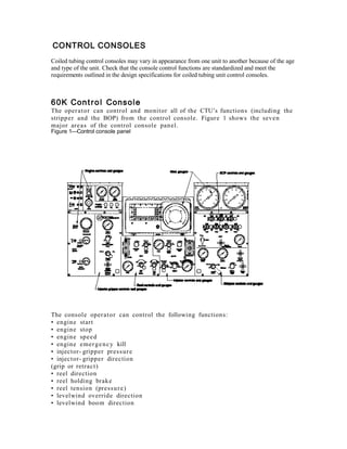
  • 1. CONTROL CONSOLES Coiled tubing control consoles may vary in appearance from one unit to another because of the age and type of the unit. Check that the console control functions are standardized and meet the requirements outlined in the design specifications for coiled tubing unit control consoles. 6 0 K Con t r o l Cons o l e The oper a t or can control and monitor all of the CTU’s functions (including the stripp e r and the BOP) from the control console. Figure 1 shows the seve n major are a s of the control console pan el. Figure 1—Control console panel The consol e oper a t or can control the following functions: • engin e start • engin e stop • engin e spe e d • engin e eme r g e n c y kill • injector- gripper pres s ur e • injector- gripper direction (grip or retra c t) • reel direction • reel holding brake • reel tension (pre s s u r e ) • levelwind override direction • levelwind boo m direction
  • 2. • injector holding brake • injector direction (in or out) • injector pres s u r e • injector- mot or displac e m e n t • stripp e r position (strip or retr a c t) • stripp e r pres s ur e • stripp e r hand- pump pres s u r e • auxiliary BOP ra ms (thre e) • BOP blind ra m • BOP cutt e r ra m • BOP tubing ra m • BOP slips ra m • accu m ul a t or pre s s ur e The consol e oper a t or can monitor the following para m e t e r s : • wellhe a d pres s ur e • tubing pres s ur e • weight indicat or • console oper a tin g pres s ur e • console pilot control pres s ur e • power- pack a g e engine tacho m e t e r • injector grippe r pres s ur e • reel pump pres s ur e • injector pump pres s ur e • injector pump torqu e / s p e e d pres s ur e • strippe r hydr a ulic pres s ur e • strippe r hydr a ulic supply (oper a tin g) pres s u r e • BOP hydr a ulic supply pres s u r e • alter n a t or char ging for both the power pack and the hous e The consol e cont ains ma n u a l hydr a ulic pu mp s that can supply e me r g e n c y pres s u r e for the control of vital functions if the main pump fails. All direction al control valves are close d when the knob or lever is cent e r e d . Engine Control The engin e controls are locat e d in the uppe r left are a of the control console pan el (Figur e 1) The engine control are a of the control console pan el is shown in Figure 2. Figure 2—Engine control area of the console
  • 3. The START , s TOP , and EMERGENCY KILL push button s start and stop the engine . All engin e controls are pne u m a t i c ally oper a t e d . The AIR THROTTLE regula ting valve controls the engine spe e d. Clockwis e rota tion of the valve incre a s e s engin e spe e d. The tacho m e t e r at the far left side of the control consol e pan el shows the engin e spe e d . Note If you use the EMERGENCY KILL, you mus t res e t the kill cylinder before the engin e will rest a r t. The controls for the outsid e flood lights, the air condition e r, and the hea t e r are also in this are a . Undern e a t h the tacho m e t e r controls are the volt me t e r s desig- nat e d for both the power pack and the hous e alter n a t o r s . Primary Injector The PRIMARY INJECTOR or “gripp er” controls are locat e d on the left side of the consol e (Figur e 1). The grippe r control are a of the control- console pan el is shown in Figure 3.
  • 4. Figure 3 – Primar y Injector or Gripper control are a of the consol e The GRIPPER POSITION lever controls the eng a g e m e n t of the grip cylinde r s and the gripper blocks. The lever has two positions: GRIP and RETRACT. Once it is place d in the require d position, the lever locks in place. Positioning the gripper position lever to the GRIP or RETRACT position direct s hydr a ulic pres s u r e to the linearbe a m grip cylinder s . In the grip position, applied pres s ur e to the grip cylinder s caus e s the linear be a m s to exert pres s u r e on the tubing OD throug h the grippe r blocks. Sufficient pres s ur e prev e n t s the tubing from sliding in the gripper blocks as the tubing is inject e d into or re mov e d from the well. Turning the GRIPPER PRESSURE ADJUST knob clockwis e incre a s e s the grippe r pres s u r e . The gripper pres s ur e mus t be adjust e d to a level high enoug h to preve n t slippa g e of the tubing at oper a ting loads. Although pres s ur e can be incre a s e d from the consol e, the oper a t or mus t first adjus t the pres s ur e to the require d value and the n open the blee d valve at the injector' s accu m ul a t or until the pres s ur e is stabilize d at the requir e d value. This proc e s s is nec e s s a r y bec a u s e of a safet y pilot- oper a t e d check- valve that preve n t s the loss of be a m pres s u r e whe n hydr a ulic pres s ur e is lost.
  • 5. The OPEN FOR GRIPPER HAND PUMP valve should be close d und er nor mal oper a tin g conditions. If, howev e r, hydr a ulic pres s u r e is lost, the accu m ul a t or on the injector should hold grippe r pres s u r e . If this accu m ul a t or pres s ur e start s drop- ping, ope n the OPEN FOR GRIPPER HAND PUMP valve by turning the valve count e r- clockwis e. Then use the ma n u al hand pu mp locat e d und er the console to hold pres s u r e on the gripper blocks until the BOP can be activat e d or until the tubing is sta ble. To maint ain control of the coiled tubing workstring, you mus t apply sufficient linear be a m pres s u r e to the tubing to prev e n t slippa g e betw e e n the tubing and the gripper blocks. The reco m m e n d e d linear be a m pres s u r e for a given hoisting load for the 60k injector is define d by the following equ a tion s: p = 200 psi (whe n Q < 10,00 0 lb) p = Q ÷ 50 psi (whe n Q > 10,000 lb) wher e p is the hydr a ulic pres s u r e (psi) applied to the linear be a m cylinder s (indica t e d by the oper a t or control cons ol e gaug e labele d GRIPPER PRESSURE ) and Q is the axial hoisting load (lb) on the tubing. Note Thes e reco m m e n d e d value s are bas e d on cons e rv a tiv e ass u m p - tions. Many factor s affect the gripping efficiency of the gripper blocks. Therefor e , differe n t be a m pres s u r e s ma y be use d bas e d on the conditions pres e n t . Exces sive gripper pres s ur e plac e s unn e c e s s a r y stre s s on the tubing and can result in decr e a s e d tubing life and da ma g e to the tubing. See the Gripper Block for Coiled Tubing Injectors Manual (Part No. 70.51 1 4 0) for reco m m e n d e d gripper pres s u r e s for various tubing sizes and wall thickne s s e s . The GRIPPER PRESSURE gaug e indicat e s the pres s ur e applied to the grippe r. Reel Controls The reel and levelwind controls are locat e d in the REEL are a at the botto m of the control consol e (Figur e 1). The reel control are a of the control- consol e pan el is shown in Figure 4 Figure 4—Reel control area of the console
  • 6. The REEL TORQUE LEVER controls the direction and winding force of the tubing reel. The lever oper a t e s the direction al valve to the main reel mot or. The SLACK (spool- off) position caus e s the reel to rota t e in a direction that unwinds the coiled tubing. Cauti o n Car e sh o u l d be tak e n to pre v e n t th e tubi n g fro m un w r a p pin g an d birdn e s t i n g w h e n th e re e l is in th e sla c k mo d e . Unwr a p p i n g coul d re s u l t in tubi n g da m a g e . The TENSION (spool- on) position caus e s the reel to rota t e in a direction that rewinds the coiled tubing. During nor mal oper a tion s , the reel is kept in the TENSION position all the time to ens ur e that the coiled tubing re mai n s tightly wound on the reel. The MAX PRESS ADJUST knob controls the hydr a ulic pres s u r e to the reel drive mot or. This knob is conn e c t e d to the high- and low- set pres s ur e- relief valves locat e d on the reel’s power pack ma nifold block. Turning the knob clockwis e incre a s e s the torqu e of the reel drive mot or. Monitor the reel pres s u r e during the job and adjust it as nec e s s a r y to maint ain a consist e n t coiled tubing wrap on the reel. The PUMP pres s u r e gaug e indicat e s the reel pu mp pres s u r e whe n the REEL TORQUE valve is in the TENSION position. The HOLDING BRAKE knob set s and rele a s e s the brake on the reel. The reel holding brake is locat e d inside the reel plan e t a r y ge ar box. The brake is a fail-safe, disc- type, spring- set/pr e s s u r e - rele a s e brak e. In the SET position, the hydr a ulic pres- sure is du mp e d off the brak e piston, and the springs set the brak e. In the RELEASE position, pre s s ur e is applied to the brak e piston and the brak e is rele a s e d to allow reel rotation. Cauti o n Do no t s e t th e re e l hol di n g brak e w hil e th e re e l is turni n g . The re e l hol di n g brak e is a parki n g brak e onl y . Occasion al interru ption of the auto- levelwind ma y be nec e s s a r y to ens ur e that the tubing wraps are unifor m. The LEVELWIND OVERRIDE knob allows the oper a t or to interru pt the auto m a ti c levelwind me c h a ni s m on the reel to adjus t the wraps of
  • 7. tubing. The knob is spring- bias e d to the cent e r (neutr al) position. When the knob is relea s e d , it stops the override function and re- eng a g e s the auto m a t ic levelwind. The LEVELWIND BOOM knob allows the levelwind tubing guide to be raise d ( UP ) or lower e d ( DOWN ) so that the correct relations hi p betw e e n the reel and the injector tubing guide can be ma d e for optimu m oper a tion. The valve is also springbias e d to the cent e r position. Injector Controls The injector pu mp and motor controls are locat e d at the botto m cent e r of the consol e (Figur e 1). The injector control are a of the control console pan el is shown in Figure 4. Figure 4 –Injector control area of the console The INJECTOR SPEED lever (Munson- Tyson valve) controls the spe e d and direction of the injector. Specifically, it direct s pilot pres s ur e to the injector direction al control, which both est a blish e s the direction of the injector and functions as a flow- control valve that controls the a mo u n t of fluid to the motor s . The injector spe e d is controlled relative to how far from the cent e r position the lever is place d. The injector is station a r y when the lever is cent e r e d , and the injector is at full spe e d when the lever is positione d in either of the extre m e positions. The MAX PRESS ADJUST knob controls the hydr a ulic pres s u r e at the injector drive mot or s. The knob oper a t e s by venting the main relief valve on the power pack a g e’ s injector ma nifold. Turning the MAX PRESS ADJUST knob clockwis e incre a s e s the power of the injector mot or s. The MAX PRESS ADJUST knob should be adjus t e d to the mini mu m a mo u n t of pres s ur e nec e s s a r y to overco m e the load- induc e d resist a n c e .
  • 8. The PUMP pres s u r e gaug e indicat e s the injector mot or pres s ur e regar dl e s s of the direction of rota tion. The gaug e also acts as a spar e weight indicator by taking the pres s u r e shown and multiplying by a factor of 12. Note The weight indicator is a mor e accur a t e device for me a s u ri ng the actu al injector forces. The LOW SPEED / HI TORQUE / VAR knob allows the oper a t or to select the injector mot or’s mod e of oper a tion. In the LOW SPEED / HI TORQUE mod e , the motor s oper a t e at ma xi mu m displac e m e n t (low spe e d) for maxi mu m torqu e . In the VAR (variable) mod e , the oper a t or can cha ng e the mot or displac e m e n t , and ther efor e, affect the injector motor spe e d and torqu e in speci al applications . Note When the injector is in variabl e mod e , the backpr e s s u r e on the syst e m can caus e the injector spe e d to cha ng e . For exa m pl e , oper a ti ng the levelwind override caus e s the return pres s u r e to incre a s e ; the incre a s e in retur n pres s u r e caus e s the injector spe e d control pres s u r e to incre a s e , which caus e s the injector spe e d to incre a s e . The ADJUST knob to the right of the LOW SPEED / HI TORQUE / VAR knob controls the spe e d and torqu e of the motor s in the VAR mod e . Clockwis e rota tion of the knob incre a s e s mot or spe e d and caus e s a corre s p o n di n g decr e a s e in availabl e torqu e . The pres s u r e gaug e next to the ADJUST knob indicat e s the injector mot or control pres s u r e . The HOLDING BRAKE knob controls the injector holding brake s inside the plan e t a r y ge ar boxe s that drive the injector. The brak e s are fail-safe, disc- type, springset/ pres s u r e- relea s e brake s . In the SET position, the hydr a ulic pres s u r e is re mov e d from the brake piston, and the springs set the brake . In the RELEASE position, pres s u r e is applied to the brak e piston, and the brake is rele a s e d to allow rotation of the motor s . BOP Controls The valves and gaug e s controlling and displa ying the oper a tin g conditions of the BOPs are locat e d on the right side of the console. (See Figure 1) The BOP control are a of the control cons ol e is shown in Figure 5. Figure 5—BOP control area of the console
  • 9. The BLIND, CUTTER , SLIPS , and TUBING levers control the ra ms on the qua d blowout preve n t e r . The thre e spar e levers allow the oper a t or to control additional safet y BOPs. For all BOP ra ms , the control- valve levers are locke d in both the open and close position to prev e n t inadve r t e n t selection of either mod e . The BOPs are nor mally eng a g e d whe n the tubing is station a r y. Closing the BOP ra ms while running tubing can interfer e with tubing oper a tion s and da m a g e the tubing. Dyna mic well- pres s ur e control is maint ain e d with the strippe r. To activat e the BOP ra ms , disen g a g e the locks, place the valve in the CLOSE position, and eng a g e the locks. To retra c t the ra ms , plac e the valve in the OPEN position. If a syst e m hydr a ulic failure occur s, a check valve on the supply side of the BOP control ma nifold isolat e s the BOP controls. The hous e’s accu m ul a t or pack a g e can supply power to oper a t e the BOPs if the main syst e m pre s s ur e is lost. A hand pu mp is also available as a final e me r g e n c y supply. The SUPPLY pres s u r e gaug e indicat e s the hydr a ulic pre s s ur e available for oper a t- ing the BOPs. The gaug e doe s not indicat e the pres s u r e available from the accu m ul a t or s . In the eve nt of power loss from the power pack a g e , the accu m ul a t or s store ener g y in the form of fluid pres s ur e . The accu m ul a t or s store enoug h ener g y to close all BOP ra ms 1.5 time s or to close, open, and close all the ra ms unde r “worst cas e ” conditions. The OPEN FOR BOP HAND PUMP valve should be close d unde r nor m al oper a ti ng conditions. If hydr a ulic power is lost, the accu m ul a t or s should supply power to activa t e the BOPs. If, howe v e r , accu m ul a t or pres s ur e is lost, open the OPEN FOR BOP HAND PUMP valve by turning the valve count e r clockwis e . To activat e the BOP, eng a g e the BOP ra m knob and use the ma n u a l hand pump. The ACCUMULATOR lever control rele a s e s pres s ur e stor e d in the accu m ul a t o r s after a job. All pres s u r e should be relea s e d befor e any hos e s are disconn e c t e d .
  • 10. Stripper Controls The valves and gaug e s controlling and displa ying the oper a tin g conditions of the stripp e r are locat e d at the lower right side of the consol e (Figure 1). The stripp e r controls are a of the control consol e is shown in Figure 6. Figure 6—Stripper control area of the console The STRIPPER POSITION lever direct s hydr a ulic pres s u r e to the strippe r. Moving the lever to the STRIP position applies pres s ur e to the port which squ e e z e s the stripp e r aroun d the tubing. This action provide s a seal aroun d the tubing to control wellhe a d pres s ur e . The RETRACT position re mov e s pres s ur e from the stripp e r. The STRIPPER PRESSURE ADJUST knob controls the a mo u n t of pres s u r e (sque e z e ) place d on the tubing. Turning the knob clockwis e incre a s e s the pres s ur e . The HYDRAULIC SUPPLY pres s u r e gaug e indicat e s the pres s u r e available for oper a ti ng the stripp e r. The STRIPPER PRESSURE gaug e indicat e s the pres s ur e being applied to the strippe r. The OPEN FOR STRIPPER HAND PUMP valve should be close d und er nor mal oper a tin g conditions. If, howev e r, hydr a ulic pres s u r e is lost, ope n the OPEN FOR STRIPPER HAND PUMP valve by turning the knob count e r clockwis e . Make sure that the STRIPPER POSITION valve is in the correct position and use the hand pu mp locat e d und er the console. To rele a s e the hand pump pres s ur e to the stripp e r, open the valve labele d STRIP - PER DUMP . The STRIPPER DUMP valve can also be use d to reduc e the strippe r pres s u r e without moving the STRIPPER POSITION lever into its RETRACT position.
  • 11. Miscellaneous Instrumen ts Miscellan e o u s gaug e s and instru m e n t s are locat e d in the upp er cent e r, upp er left, and uppe r right of the control console pan el (Figure 1). Thes e are a s of the control consol e pan el are shown in figure 7. Figure 7 – Miscellaneous instruments area of the control console. . The CONSOLE PRESSURE gaug e indicat e s the oper a tin g pres s ur e of the main hydr a ulic syst e m. The PILOT PRESSURE gaug e indicat e s the console pres s ur e provide d (500 psi or 3400 kPa) to oper a t e other cons ol e valve s. The WELLHEAD PRESSURE gaug e indicat e s the wellhe a d pres s ur e . The gaug e is isolat e d from the well fluids by a pres s ur e deboos t e r . The TUBING PRESSURE gaug e indicat e s the pres s u r e on the tubing. The gaug e is isolat e d from the well fluids by a pres s ur e deboos t e r . Cauti o n The WELLHEAD PRESSURE ga u g e and th e TUBING PRESSURE ga u g e ar e sp e c i a l ga u g e s wit h a 1:4 s e n s i n g - to- indi c a t i n g rati o . If repl a c e d , th e s e ga u g e s mu s t be re pl a c e d wit h ide n t i c a l ga u g e s . Failur e to do so will re s ul t in pr e s s u r e re a d i n g s tha t ar e onl y 25% of th e ac t u a l w ell h e a d or tubi n g pr e s s u r e . The digital and analog weight indicat or s indicat e the weight being suppor t e d by the load pins locat e d at the botto m of the injector. If prope rly “zeroe d, ” the s e weight indicator s will indicat e the tubing loads, such as tubing weight and snubbing force. Both weight indicat or s are a part of the dat a acquisition syst e m (DAS). See Section 10, 60k CTU Data- Acquisition Syst e m and the DAS ma n u a l s (Part No. 516.9 9 0 0 6 and Part No. 516.9 9 0 0 7) for mor e infor ma tio n.
  • 12. 3 0 K/ 3 8 K Con t r o l Con so l e The operator can control and monitor all of the CTU’s functions from the control console. Figure 8 shows the controls for a standard 30/38K coil tubing unit. Figure 8 -
  • 13. .25 D T I L C. E AL O SCA E F L L UL TP Y 6 PA S L CE 14 16 48 59 56 55 14 CO SO E N L PE R SSUR E 11 23 3 4 7 70 56 57 62 I J CO NE TR I N P E UR R SS E BA EM PE R SSUR E 69 14 IJCO NE T R OT U PE R SSUR E B OP PE R SSUR E ST I P R RP E PE R SSUR E C AN HI OL R IE 21 CO SOL N E LG T I HS BA EM PE R SSUR E A J ST DU LG T I HS HG IH OF F LW O H AE ETR C AE RN 48 A /C WL ED E HA L PE R SSUR E IJCO NE T R I N I J CO NE TR A J ST DU T BN UI G PE R SSUR E OT U HR ON 73 R E MT R EL OO PE R SSUR E R E A JU E L D ST 80 HG IH O N D P UM RE EL C I N LW O LA OD OT U O N D P UM LA OD LA OD ST P O AR I PE R SSUR E O N OF F O N OF F DM UP OF F OF F AR I R G A OR E UL T 63 46 16 14 PM B UP AX U BA EM AX U B OP P PC UM 31 31 AX U ST I P R RP E 31 63 46 63 67 73 6 C SE CU D T I E T E AL F RH N L S O A DE 80 CU H N L S A D T A DE N T R A 1/2 - 13N HE D C F 1.00 6.50 CU H N L S A D T A DE N T R A 1/2 - 13N HE D C F F 1.00 5.50 56 59 8 15 G SE D T I E E AL F CU H N L S A D T A DE N T R A 1/2 - 13N HED C 1.00 7.00 1.00 D S 12- 0993 LH J _ F 4.50 H N L CUT O F D T I A DE F E AL The console operator can control the following functions: - engine start - engine stop - engine speed - engine emergency kill - injector gripper pressure - injector gripper direction - reel direction - reel tension - levelwind override direction - injector direction(in or out) - injector speed - injector speed selector (high and low) - stripper pressure - stripper position - BOP blind rams - BOP cutter rams - BOP tubing rams - BOP slip rams - auxiliary BOP rams (three) - accumulator pressure The console operator can monitor the following parameters: - wellhead pressure 60 C VE IW CU H N L S A D T A DE N T R A 1/2 - 13N HE D C T R TL HO T E 996 494- C .15 ST I P R RP E 55 56 59 G EE MR KL IL L VL I D EE W N OF F P PA UM 22 DM UP ST R AT C WI H I DCA O EG T N I T R BA EM PE R SSUR E SP E ED C NRL OTO 12- 2993 _ I ST N M N L- I SC - H USE O E A O O - PRTR COL T I G T AL R I UBN R I E 3/8 I B 03- 03- 97 E 04 08 G 278.99742
  • 14. - tubing pressure weight indicator console operating pressure injector gripper pressure reel tension pressure stripper hydraulic pressure BOP supply pressure The console contains manual hydraulic pumps that can supply emergency pressure for the control of vital functions if the main pump fails. All directional control valves are closed when the knob or lever is centered. Engine Control The START, STOP, and EMERGENCY KILL push buttons start and stop the engine. All engine controls are pneumatically operated. The AIR THROTTLE regulating valve controls the engine speed. NOTE: If you use the EMERGENCY KILL, you must reset the kill switch on the power pack before the engine will restart. Injector Controls Injector “In – Out” (Directional Control) The injector direction is selected manually by positioning the lever to the “in” or “out” position. This valve directs pilot pressure to the main directional control valve located on the power pack and causes the valve to supply power to the injector drive motor ports. Injector Adjust (Pressure Control) The hydraulic pressure at the injector drive motors can be limited by adjusting the “injector pressure control” valve. This valve is an adjustable relief valve that is connected by a hose to the vent port on the main relief valve on the injector manifold block of the power pack. Turning the injector adjustment valve knob counterclockwise causes the maximum pressure directed to the injector motors to decrease. The adjusted pressure is the maximum pressure that is available to do work. It is a good operating practice to adjust this control only high enough to overcome the load induced resistance. Injector ‘In – Out” Pressure Gauges Two pressure gauges are mounted to the panel. One indicates the actual injector motor pressure in the “in” direction and the other in the “out” direction. By monitoring the pressure on the gauge and using the pressure factor found in the Injector section of the manual for the injector in use the operator may calculate the approximate load. NOTE: The weight indicator is a more accurate device for measuring the actual injector forces. Beam Pressure (Injector Gripper Control) Positioning the Beam Pressure control lever to the “on” or “off” position directs hydraulic pressure to the linear beam cylinders. Application of pressure to the “on” cylinder ports causes force to be exerted on the tubing OD by the linear beams. The force then generates the frictional reaction force necessary to grip the tubing without sliding the gripper blocks on the tubing. NOTE: This control should have a “Weevil lock” on it to keep it from being accidentally moved to the “off” position while pipe is in the hole. Beam Pressure Adjust (Injector Gripper Pressure Control) The magnitude of the tubing frictional force is proportional to the amount of lateral force generated by the gripper cylinders. The gripper pressure must be adjusted to a level high enough to prevent slippage of the tubing at the operating loads. Too high a setting, however, places unnecessary
  • 15. stresses on the tubing. Higher stresses cause the life of the tubing to decrease. High gripper pressures also accelerate the wear rate on the injector chain components. A nominal setting of 1000 psi is recommended. Turning the knob clockwise increases the gripper pressure. Gripper pressure is isolated at the injector by a pilot operated check valve. Reducing the pressure on the house gauge will not reduce the pressure on the gripper beams. If the pressure needs to be reduced there is a bleed off valve on the injector where this may be done. The operator must first adjust the pressure to the required setting and then open the bleed off valve until the pressure is stabilized. Extreme care should be taken when doing this. NOTE: Refer to the “Gripper Block for Coiled Tubing Injectors Manual” (Part # 70.51140) for recommended gripper pressures for various tubing sizes and wall thickness. Aux. Beam If hydraulic pressure is lost on the console, the beam pressure has a check valve, which isolates it and allows pressure to be maintained on the beams. If this pressure starts dropping or needs to be raised the Auxiliary Beam two-way valve should be switched from the “Off” position to the “On” position. There is an emergency hand pump, located below the console, that will allow the operator to supply pressure to the beams when this valve is in the “On” position Beam Pressure gauge The gauge “Beam Pressure” indicates the amount of hydraulic pressure that is being applied to the gripper cylinders on the injector. Speed Control “High – Low” The injector speed selector has a pre-set pressure on most units and only needs to be shifted to high or low to be activated. On some older units this control has a pressure control adjustment which needs manually set. This should be set at 1500 psi. When running in the hole the 30K injector should be shifted from high to low when the weight reaches approximately 10,000 lbs. When pulling out of the hole it may be shifted back into high when the weight reaches approximately 10,000 lbs. The injector should be stopped and put in neutral to carry out this operation. The 38K injector may be shifted at 12,000 lbs. Chain Oiler The chain oiler air operated button provides the operator with a means of lubricating the chains while tripping in and out of the hole. The chains should be oiled approximately every 10,000 running feet. Refer to the Injector section of this manual for types of acceptable lubricating oil. Pump “A”, “B”, “C” Three two-way ball valves mounted on the panel permit the operator to selectively engage the main injector drive pumps on the power pack. Setting the dump valve to the “vent” position causes the pump unloader to vent, thus diverting the entire pump flow to the tank. Venting all three valves will unload all three pumps. This is a convenient method of selecting injector speed by diverting some of the excess flow to the tank at a low pressure drop. The other method of controlling injector speed is to reduce the injector pressure until the relief valve bypasses some of the fluid flow. The excess pump flow will then be dumped across the main pressure relief valve, reducing the flow to the motors and causing the speed to decrease. A disadvantage of this speed control method is the wasted energy that is evident by the heat input into the hydraulic oil. Reel Controls Reel “In – Out” (Directional Control)
  • 16. The Reel directional control valve is used to select the direction that the reel turns. Positioning the lever to either the “In” or “Out” position causes a pilot signal to shift the main reel motor directional valve (on the power pack) in the direction to power the reel motor to the “in” or “out” direction. In most normal operations, the reel will always be in the “out” mode, whether going in or pulling out of the hole. It is necessary to maintain tension on the reel to prevent birdnesting. Reel Adjust The Reel Adjust valve allows the operator to adjust the pressure that is powering the reel drive motor. Turning the knob counterclockwise decreases the pressure at the motor port. This valve is connected to the high and low set pressure reducing relief valves located on the power pack reel manifold block. The reel pressure should be monitored during the job and adjusted as necessary to maintain a consistent wrap on the reel. Reel Motor Pressure gauge The reel pressure gauge located on the panel permits the operator to monitor the hydraulic pressure to the reel drive motor that is producing the tension on the tubing. Levelwind Occasional interruption of the auto-levelwind may be necessary to ensure that the tubing wraps are uniform. The “Levelwind” directional control knob allows the operator to override the autolevelwind when necessary. The operator should observe the direction that the levelwind carriage moves when the valve is selected. BOP & Stripper Controls BOP Control Valves The Blind, Cutter, Slips and Tubing levers control the rams on the quad blowout preventer. The three spare levers allow the operator to control additional safety BOP’s. For all BOP rams, the control valve levers are locked in the open position to prevent accidental closing. The BOP’s are normally engaged when the tubing is stationary. Closing the BOP rams while running tubing can interfere with tubing operations and damage the tubing. To activate the BOP rams, disengage the locks and place the valve in the CLOSE position. To retract the rams, place the valve in the OPEN position. BOP Pressure gauge The BOP Pressure gauge allows the operator to see the hydraulic pressure available for the BOP functions. Aux. BOP If a system hydraulic failure occurs, a check valve on the supply side of the BOP control manifold isolates the BOP controls. The house’s accumulator package can supply power to operate the BOPs if the main system pressure is lost. The Auxiliary BOP two-way valve should be switched from the “Off” position to the “On” position and the desired BOP valve selected. A hand pump, located below the console, is also available as a final emergency supply. Stripper The stripper valve is a two way valve that allows the operator to select the “Dump” position for decreasing or bleeding off the pressure on the stripper or select the “Off” position to maintain the required hydraulic pressure on the stripper.
  • 17. Air Regulator The Air Regulator allows the operator to adjust the amount of air pressure needed to activate the pneumatically powered pump mounted underneath the console. This pump supplies the pressure to hydraulically energize the stripper packoff. Air Pressure gauge The air pressure gauge located on the console lets the operator see how much air pressure is being applied to the pneumatic powered pump. Stripper Pressure gauge The stripper pressure gauge allows the operator to see how much hydraulic pressure is being applied to the stripper packoff. Aux. Stripper In the event of a system hydraulic failure or loss of air supply, a check valve on the supply side of the stripper isolates the stripper to prevent loss of pressure. The auxiliary stripper two-way valve may be switched from the “Off” position to the “On” position and pressure may be supplied with the emergency hand pump, located below the console. Miscellaneous Instruments The Console Pressure gauge indicates the console pressure available to operate the console valves. This pressure should normally be at 1500 psi. The Wellhead and Tubing Pressure gauges read the pressures on the wellhead and tubing. These gauges are each isolated from well fluids by pressure deboosters. NOTE: On some units these gauges are special gauges with a 1:4 sensing to indicating ratio. If replaced, these gauges must be replaced with identical gauges. Failure to do so will result in pressure readings that are only 25% of the actual pressure. Weight Indicators may be digital, analog or bladder type. The digital and analog weight indicators indicate the weight being supported by the load pins located at the bottom of the injector. If properly “zeroed,” these weight indicators will indicate the tubing loads, such as tubing weight and snubbing force. Both indicators are a part of the Data Acquisition System (DAS). See the DAS manual (part # 516.99007) for more information. The bladder type (Martin-Decker) weight indicator only indicates tubing weight and will not measure snubbing forces. There are toggle switches located on the console for operation of lights, heater, air conditioner and crane on most units.