
Empfohlen
Weitere ähnliche Inhalte
Was ist angesagt?
Was ist angesagt? (20)
Andere mochten auch
Andere mochten auch (14)
Kürzlich hochgeladen
Kürzlich hochgeladen (20)
Aet 142 starting_system_2_
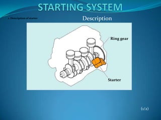
- 1. 1. Description of starter Description Ring gear Starter (1/2)
- 2. Outline 2. Type of starter (1) Reduction type (1) Reduction type Yoke Armature Drive gear Magnetic switch Pinion gear (2/2)
- 3. Outline (2) Conventional type (2) Conventional type Magnetic switch Drive lever Pinion gear Yoke Armature (2/2)
- 4. Outline (3) Planetary type (3) Planetary type Magnetic switch Drive lever Armature Yoke Planetary gear Pinion gear (2/2)
- 5. (4) Planetary reduction-segment conductor motor (PS) type (4) Planetary reduction-segment conductor motor (PS) type Magnetic switch Armature Pinion gear Permanent magnet Planetary gear (2/2)
- 6. Outline Characteristics Speed Starter speed Torque Output Voltage (N m) Voltage Torque (kW) (V) (rpm) Output Current (1/1)
- 7. Reduction Starter Components Yoke sub-assembly Armature Brush and brush holder Reduction gear Magnetic switch Pinion gear Overrunning clutch and helical spline (1/1)
- 8. Reduction Starter 1. Magnetic switch Construction 1. Magnetic switch Main contact Plunger Return spring Drive spring Plunger shaft Hold-in coil Pull-in coil (1/2)
- 9. Reduction Starter 2. Armature and ball bearing Construction 2. Armature and ball bearing Ball bearing Armature coil Ball bearing Commutator Armature core (1/2)
- 10. Reduction Starter 3. Yoke sub-assembly Construction 3. Yoke sub-assembly Yoke Brush Pole core Field coil (1/2)
- 11. Reduction Starter 4. Brush and brush holder Construction 4. Brush and brush holder Brush holder Body ground Brush Brush spring (2/2)
- 12. Reduction Starter 5. Reduction gear Construction 5. Reduction gear Drive gear Reduction gear Idle gear Clutch gear Ball bearing Ball bearing (2/2)
- 13. Reduction Starter 6. Overrunning clutch Construction 6. Overrunning clutch Clutch roller Spline shaft Return spring Pinion gear Clutch gear Pinion shaft (2/2)
- 14. Reduction Starter 7. Pinion gear and helical spline Construction 7. Pinion gear and helical spline Spline shaft Pinion gear Helical spline Pinion shaft Ring gear (2/2)
- 15. Reduction Starter 1. Magnetic switch Operation Magnetic switch (1/7)
- 16. Reduction Starter (1) General Operation 2 functions Pinion gear Motor engagement/ ON/OFF disengagement Pull-in Turns ON Engages Hold-in Transmits the 3 steps Holds at ON revolving force Return Turns OFF Disengages (1/7)
- 17. Reduction Starter SERVICE HINT: Operation Internal wiring diagram Pull-in coil Field coil Main contact Planger Contact plate Ignition Hold-in coil switch (1/7)
- 18. Reduction Starter Operation (2) Operation <1> Pull-in (2/7)
- 19. Reduction Starter Operation Battery Ignition switch Hold-in coil Pull-in coil Ground Field coil Armature coil Ground (2/7)
- 20. Reduction Starter Operation <2> Hold- in (3/7)
- 21. Reduction Starter Operation Battery Ignition switch Contact plate Hold-in coil Field coil Ground Armature coil Ground (3/7)
- 22. Reduction Starter Operation <3> Return (4/7)
- 23. Reduction Starter Operation Battery Contact plate Pull-in coil Field coil Hold-in coil Armature coil Ground Ground (4/7)
- 24. Reduction Starter Operation 2. Overrunning clutch Clutch roller Clutch Clutch roller spling Spline shaft (inner) Pinion Return gear spring Spline Clutch gear shaft Pinion shaft Clutch gear (outer) (inner) (outer) (5/7)
- 25. Reduction Starter (1) Operation <1> While the engine cranks Operation <1> While the engine cranks (5/7)
- 26. Reduction Starter <2> After the engine starts Operation <2> After the engine starts (5/7)
- 27. Reduction Starter Operation 3. Engagement/disengagement mechanism (1) General Armature Revolving force Push from magnetic switch Helical spline (6/7)
- 28. Reduction Starter (2) Engagement mechanism Operation Click on the illustration. (6/7)
- 29. Reduction Starter Operation HINT: Pinion Ring gear gear Chamfer (6/7)
- 30. Reduction Starter Operation (3) Disengagement mechanism Helical spline Revolving force Thrust Return spring (7/7)
- 31. Reduction Starter Operation Pressure (Low) Pressure to disengage the pinion gear (Low) Revolving speed (Same) (7/7)
- 32. Reduction Starter Operation Return spring (7/7)
- 33. Conventional Starter 1. Construction differences between the conventional type and the reduction type Other Constructions of Starter Engagement/disengagement Speed reduction Brake of the pinion gear mechanism mechanism Reduction type Magnetic switch Yes No Conventional Magnetic switch No Yes, No type and drive lever (1/4)
- 34. Conventional Starter 2. Engagement/disengagement of the pinion gear 3. Speed reduction mechanism Magnetic switch Drive lever Drive spring (1/4)
- 35. Conventional Starter Other Constructions of Starter 4. Brake mechanism Lock plate Brake spring Armature Commutator end frame (2/4)
- 36. Conventional Starter 1. Construction differences between the planetary type, the reduction type and the conventional type Other Constructions of Starter Engagement/disengagement Speed Brake of the pinion gear reduction mechanism mechanism Reduction type Magnetic switch Yes No Conventional No Yes, No type Magnetic switch and drive lever Planetary type Yes No (3/4)
- 37. Conventional Starter 2. Engagement/disengagement of the pinion gear Other Constructions of Starter Drive spring (built in the magnetic switch) Drive lever (3/4)
- 38. Conventional Starter 3. Speed reduction mechanism (1) Construction (2) Characteristics Other Constructions of Starter <Operation of the planetary gear> Sun gear : Drive Planetary gear : Reduce Armature Planetary carrier Sun gear Planetary carrier : Output Internal gear Planetary gear (4/4)
- 39. Conventional Starter (3) Operation Other Constructions of Starter Click on the illustration. (4/4)
- 40. Conventional Starter Other Constructions of Starter REFERENCE: (4/4)
- 41. Conventional Starter Other Constructions of Starter (4/4)
- 42. Reference 1. Field coil PS (Planetary reduction-Segment conductor motor) Starter Main magnet Interpolar magnet Magnetic flux generated by main magnet Magnetic flux generated by relationship between main and interpolar magnets (1/2)
- 43. Reference 2. Armature PS (Planetary reduction-Segment conductor motor) Starter Conventional type starter Armature Brush Commutator Brush Armature Surface PS starter commutator Square-shaped Round-shaped conductor conductor wire B-B cross section A-A cross section conventional type PS starter starter (2/2)
- 44. Inspection 1. Check battery terminal voltage Inspection of the Battery Voltage Check battery terminal voltage START (1/2)
- 45. Inspection 2. Check terminal 30 voltage 3. Check terminal 50 voltage Inspection of the Battery Voltage Check terminal 30 voltage START Terminal 30 Check terminal 50 voltage Terminal 50 (2/2)