SlideShare ist ein Scribd-Unternehmen logo
1 von 8
Downloaden Sie, um offline zu lesen
(12) United States Patent
US007257918B2
(10) Patent N0.: US 7,257,918 B2
Moore (45) Date of Patent: Aug. 21, 2007
(54) DOUBLE ACTION, HAMMER TRIGGER 4,275,640 A 6/1981 Wilhelm
MECHANISM FOR A FIREARM 4,428,138 A 1/1984 Seecarnp
5,216,195 A 6/1993 Tuma
(76) Inventor: Wildey J. Moore, 45 Angevine Rd., 5,386,659 A 2/1995 Vaid et a1~
Warren’ CT (Us) 06794 5,400,537 A 3/1995 Meller et a1.
5,426,880 A 6/1995 Ruger et a1.
( * ) Notice: Subject to any disclaimer, the term of this 6,457,271 B1 10/2002 Vaid et a1~
patent is extended Or adjusted under 35 2001/0042332 A1 11/2001 Gering et a1.
U.S.C. 154(b) by 326 days.
FOREIGN PATENT DOCUMENTS
(21) Appl. No.: 10/527,859 EP 0 550 238 A1 7/1993
(22) PCT Filed: Sep. 26, 2003
Primary ExamineriMichelle Clement
(86) PCT No.: PCT/US03/30290 (74) Attorney, Agent, or FirmiMcCormick, Paulding &
Huber LLP
§ 371 (0X1),
(2), (4) Date: Mar. 15, 2005 (57) ABSTRACT
(87) PCT Pub- N05 W02004/033983 Double action, hammer trigger mechanism for a semi
automatic ?rearm (10) With a spring loaded slide (12) having
PCT Pub‘ Date: Apr‘ 22’ 2004 a cam surface (28), a pivoting sear (46) to hold the hammer
_ _ _ (20) in a cocked position and a transfer bar (26) connected
(65) Pnor Pubhcatlon Data to a pivot pin (54) on the trigger (24). The transfer bar has
US 2006/0086030 A1 Apr. 27, 2006 a cam ?nger (30) to move the transfer bar doWn When the
slide moves in a rearward direction during ?ring. When the
Related US. Application Data sear is holding the hammer cocked, a second ?nger (62) on
(60) Provisional application No. 60/416,030, ?led on Oct. the transfer bar is arranged.to engage a Single actio‘? let-0.1T
3 2002' pm (56) on the sear and pivot the sear When the trigger 1s
’ pulled so as to release the hammer. The cam ?nger also
(51) Int CL moves the transfer bar doWn When the slide is stationary and
F41A 3/00 (200601) the trigger is operated. The transfer bar has a notch (60)
(52) us. Cl. ...................................... .. 42/69.03~ 89/147 receiving a double action IeF'O?C Pin (58) 011th? hammer. to
(58) Field of Classi?cation Search 42/69.01,469.03' c‘i‘uselhe transferbm ‘9 PW“ the hammer. In a Cockmg
89/147’ direction as the trigger 1s pulled. This motion moves the
S 1. t. ?l f 1 t h h. t transfer bar notch aWay from the double action let-oif pm to
ee app 10a Ion e or Comp 6 e Seam 15 Dry‘ release the hammer When the trigger is pulled to a double
(56) References Cited action let-oifposition before the hammer reaches the cocked
position.
U.S. PATENT DOCUMENTS
3,722,358 A 3/1973 Seecamp 5 Claims, 4 Drawing Sheets
U.S. Patent Aug. 21, 2007 Sheet 2 0f 4 US 7,257,918 B2
N.A».
“a,
‘N
Q»Q,
.0.
N“.R.9“.E.
w“.“W2.
‘0?v3-N»
Sg
3ow
U.S. Patent Aug. 21, 2007 Sheet 3 0f 4 US 7,257,918 B2
54
.26’
F219.3
U.S. Patent Aug. 21, 2007 Sheet 4 0f 4 US 7,257,918 B2
US 7,257,918 B2
1
DOUBLE ACTION, HAMMER TRIGGER
MECHANISM FOR A FIREARM
CROSS REFERENCE TO RELATED
APPLICATIONS
This application claims the bene?ts of prior ?led, US.
provisional patent application Ser. No. 60/416,030, noW
abandoned ?led on Oct. 3, 2002 and International Applica
tion No. PCT/US2003/030290 ?led on Sep. 26, 2003.
TECHNICAL FIELD
This invention relates to an improved double action,
hammer trigger mechanism for a ?rearm. More particularly,
it relates to an improved mechanism for releasing the
hammer When the trigger operates a knoWn type of transfer
bar operating means to either release the hammer at a single
action let-off position, or to draW back the hammer and
release it When the trigger is pulled to a double action let-off
position.
BACKGROUND ART
A ?rearm, and in particular an autoloading or automatic
?rearm, is equipped With an external hammer that can be
cocked to the rear and engaged With a sear and then tripped
by squeezing the trigger Which engages the sear by means of
linkage releasing its engagement to the hammer (single
action let-o?‘). Alternatively, the hammer can be draWn to the
rear for release and ?ring by squeezing the trigger Without
?rst cocking the hammer. This is accomplished through the
linkage system engaging the hammer With the trigger for the
aforementioned purpose; pulling the hammer rearWard and
releasing it before it can be engaged by the sear (double
action let-o?‘).
This invention relates to ?rearms functioning in the
aforementioned manner incorporating a hammer spring,
usually located in an area behind the magaZine Well in the
frame and consisting of various components to accomplish
the single action and double action let-offs. Historically, it is
not recommended that anyone but an accomplished gun
smith Work on these mechanisms as they are complicated
and improper assembly or disassembly is very likely to
occur. The invention addresses these issues by accomplish
ing the same objectives but With basic components that
anyone With an aptitude for mechanics can easily under
stand.
Accordingly, one object of the present invention is to
provide a simpli?ed double action, hammer trigger mecha
nism for a ?rearm.
Another object of the invention is to provide an improved
single action mechanism for releasing a sear engagement
With a cocked hammer using a transfer bar connected to the
trigger.
Another object of the invention is to provide an improved
double action let-off mechanism using a transfer bar con
nected to the trigger for pulling back and releasing the
hammer before the sear engages the hammer.
Still another object of the invention is to provide an
improved hammer trigger mechanism suitable for an auto
matic or semi-automatic ?rearm of the type having a slide
operated With a recoil spring for automatic or semi-auto
matic ?ring.
20
25
30
35
40
45
50
55
60
65
2
DISCLOSURE OF INVENTION
An improved double action, hammer trigger mechanism
for a ?rearm of the type having a frame, a barrel for
receiving a cartridge, a slide or bolt arranged to move
longitudinally betWeen a forWard and a rearWard position
With respect to the barrel, the slide or bolt de?ning a cam
surface, a ?ring pin longitudinally slidable in the slide or
bolt so as to strike the cartridge, a hammer arranged to pivot
about a ?rst pivot point on the frame, the hammer de?ning
a sear notch, spring biasing means urging the hammer
toWard the ?ring pin, a spring-loaded sear arranged to pivot
about a second pivot point on the frame, the sear including
a lip for cooperating With the sear notch to hold the hammer
cocked When the hammer is pivoted, a trigger arranged to
pivot about a third pivot point on the frame, the trigger
having a trigger pivot pin thereon Which is disposed so as to
move in a forWard direction When the trigger is pulled, a
transfer bar having a ?rst end connected to the trigger pivot
pin, the transfer bar including a ?rst ?nger cooperating With
the cam surface When the slide is in a forWard position, and
a transfer spring biasing the ?rst ?nger toWard the cam
surface, the improvement comprising a single action let-off
pin disposed on the sear, the transfer bar further including a
second ?nger arranged to engage the single action let-offpin
and pivot the sear When the trigger is pulled so as to release
the hammer When the sear is holding the hammer cocked, a
double action let-off pin disposed on the hammer, the
transfer bar de?ning a notch disposed to receive the double
action let-off pin to cause the transfer bar to pivot the
hammer in a cocking direction against the spring biasing
means When the trigger is pulled to an intermediate position,
the transfer bar ?rst ?nger cooperating With the slide cam
surface to move the transfer bar notch aWay from the let-off
pin to release the hammer When the trigger is pulled to a
double action let-off position.
BRIEF DESCRIPTION OF DRAWINGS
The invention Will be better understood by reference to
the folloWing description, taken in connection With the
accompanying draWings, in Which:
FIG. 1 is a side elevational draWing, partly in section, of
a semi-automatic ?rearm,
FIG. 2 is a styliZed side elevational draWing of the
uncocked hammer trigger mechanism,
FIG. 2a is an enlarged vieW of a portion ofthe mechanism
of FIG. 2,
FIG. 3 is a side elevational draWing of the trigger mecha
nism according to FIG. 2, but With the hammer cocked for
single action let-off,
FIG. 4 is a simpli?ed draWing ofthe major components of
the trigger mechanism commencing double action hammer
rotation,
FIG. 5 is a side elevational draWing of the same mecha
nism at a later stage of double action movement, and
FIG. 6 is a side elevational vieW of the mechanism at the
double action let-off position.
BEST MODE FOR CARRYING OUT THE
INVENTION
Referring noW to FIG. 1 of the draWing, the invention is
described as embodied in a semi-automatic ?rearm of the
type using a spring-loaded cartridge magaZine (not shoWn)
and having a reciprocating slide 12 adapted to move from a
forWard position in a rearWard direction against a recoil
US 7,257,918 B2
3
spring (not shown) when a cartridge 14 is ?red. During the
rearward movement, the shell of cartridge 14 is ejected, and
during the return forward movement, a new cartridge is
stripped from the magaZine and inserted into the bore of a
barrel 16 in a manner well known in the art. Slide 12 is
reciprocable in tracks upon a frame 18. A hammer 20 is
pivotably mounted on frame 18 to strike a ?ring pin 22,
which is longitudinally slidable in the slide 12 so as to strike
the rear of cartridge 14. A trigger 24 is pivotably mounted in
the frame and connected to push or pull a transfer bar 26.
Slide 12 includes a cam surface 28, which cooperates with
a ?rst ?nger 30 to raise or lower the end of transfer bar 26
when the transfer bar is pushed or pulled longitudinally by
the trigger 24. The foregoing list of elements describes a
construction known in the prior art. The invention relates to
improvements in the linkages in the vicinity of arrow A, as
illustrated in the following ?gures.
Referring to FIG. 2 of the drawing, the hammer trigger
mechanism is illustrated at 0° of trigger rotation and 0° of
hammer rotation. Transfer bar 26 is biased upwardly by a
transfer spring 32 of a suitable type located in a magaZine
well 34. Hammer 20 is arranged to pivot about a pin de?ning
a ?rst pivot point 36 on the frame. The hammer de?nes a
sear notch 38 and is spring biased by a known type of spring
biasing arrangement having a spring 40 compressed in a
hammer spring well 42 by a hammer spring compression pin
44.
A spring-loaded sear 46 is arranged to pivot about a pin
de?ning a second pivot point 48 against a compression
spring located in a sear spring well 50. A spring-loaded sear
is well known and the spring is not illustrated in order not
to obscure the details of the invention.
The trigger 24 is arranged to pivot about a pin de?ning a
third pivot point 52 on the frame, and is pivotably connected
to transfer bar 26 by a trigger pivot pin 54. When the trigger
24 is pulled, the trigger pivot pin pulls the transfer bar 26 in
a forward direction.
In accordance with the present invention, sear 46 is
equipped with a single action let-off pin 56, and hammer 20
is equipped with a double action let-olf pin 58. As shown in
FIG. 2a, single action let-offpin 58 extends over the transfer
bar 26 between ?rst and second ?ngers 30 and 62 respec
tively, and double action let-olf pin extends over the transfer
bar 26 in alignment with notch 26.
Reference to the enlarged scale drawing of FIG. 2a, it is
seen that the end oftransfer bar 26 de?nes notch 60 disposed
to receive the double action let-olf pin 58. Further, the
transfer bar 26 de?nes a second ?nger 62, which is arranged
to engage the single action let-olf pin and pivot the sear
when the trigger is pulled.
Referring to FIG. 3 of the drawing, the hammer trigger
mechanism is shown for 49.5° of trigger rotation and 60° of
hammer rotation. Hammer 20 is shown cocked for single
action let-off, and is being held in place by sear 46. Trigger
24 has been pulled, causing transfer bar 26 to be pulled
forwardly and downwardly as dictated by the cam surface
28. The second ?nger 62 on the transfer bar is so positioned
and dimensioned to engage the single action let-olf pin 56.
This causes sear 46 to pivot and release hammer 20 to strike
?ring pin 22.
FIGS. 4 through 6 illustrate the double action let-olf
sequence. Referring to FIG. 4 of the drawing, the hammer
trigger mechanism is shown at 30° of trigger rotation and
342° of hammer rotation. As trigger 24 is pulled, the ?rst
?nger 30 begins to force transfer bar 26 in a downward
direction against transfer spring 32, as transfer bar 26 moves
forward. The notch 60 in the transfer bar engages the double
20
25
30
35
40
45
50
55
60
65
4
action let-olf pin 58 and is starting to cock hammer 20
against the compression spring 40 in hammer spring well 42.
Referring to FIG. 5 of the drawing, trigger 24 has been
drawn to a 40° rotation position to further rotate the hammer
to a 35° position against spring 40. Cam surface 28 contin
ues to cause the transfer bar 26 to move in a downward
direction against transfer spring 32. This moves notch 60 in
a direction away from the double action let-olf pin 58.
Finally, referring to FIG. 6 ofthe drawing at double action
let-olf position, the trigger has been pulled to 55° trigger
rotation, and the hammer to 492° hammer rotation. The sear
has not yet engaged the hammer to hold it in a cocked
position (FIG. 3). The ?rst ?nger 30 has lowered transfer bar
26 to the point where notch 60 no longer holds the double
action let-olfpin 58. This releases hammer 20 to strike ?ring
pin 22.
The invention has been described for a semi-automatic
?rearm with a recoil slide and the cam surface disposed in
the slide when the slide is in the forward position. The
invention is equally applicable to a ?rearm with a bolt
instead of a slide mechanism. In this case, the bolt is closed
to hold the cartridge in the chamber. When the bolt is at the
forward position, a cam surface similar to cam surface 28 is
so disposed in the bolt to cooperate with a transfer bar. The
modi?cation ofthe invention to apply to a ?rearm with a bolt
will be readily understood by one skilled in the art.
While there has been described what is considered to be
the preferred embodiment of the invention, other modi?ca
tions will occur to those skilled in the art. It is desired to
secure all such modi?cations as fall within the true spirit and
scope of the invention.
The invention claimed is:
1. Improvement in a double action, hammer trigger
mechanism for a ?rearm of a known type having a frame, a
barrel for receiving a cartridge, a slide arranged to move
longitudinally between a forward and a rearward position
with respect to said barrel, said slide being spring-loaded in
a forward direction and adapted to move in a rearward
direction when the cartridge is ?red, said slide de?ning a
cam surface, a ?ring pin longitudinally slidable in the slide
so as to strike the cartridge, a hammer arranged to pivot
about a ?rst pivot point on the frame, said hammer having
a double action let-olfpin disposed thereon and also de?ning
a sear notch, spring biasing means urging said hammer
toward the ?ring pin, a spring-loaded sear arranged to pivot
about a second pivot point on the frame, said sear including
a lip for cooperating with the sear notch to hold the hammer
cocked when the hammer is pivoted against said spring
biasing means, a trigger arranged to pivot about a third pivot
point on the frame, said trigger having a trigger pivot pin
thereon that is disposed so as to move in said forward
direction when the trigger is pulled, a transfer bar having a
?rst end connected to said trigger pivot pin, said transfer bar
de?ning a transfer bar notch disposed to receive said double
action let-olfpin so as to enable said transfer bar to pivot the
hammer in a cocking direction against said spring biasing
means when the trigger is pulled, and a transfer spring
biasing the ?rst ?nger toward said cam surface, said
improvement being characterized by:
a single action let-olf pin disposed on said sear,
said transfer bar including a ?rst ?nger cooperating with
said cam surface when the slide is in a forward position,
said transfer bar further including a second ?nger arranged
to engage said single action let-olf pin and pivot the sear
when the trigger is pulled so as to release the hammer when
the sear is holding the hammer cocked, said transfer bar ?rst
?nger being arranged to cooperate with the slide cam surface
US 7,257,918 B2
5
to move said transfer bar notch away from the double action
let-olf pin to release the hammer When the trigger is pulled
further to a double action let-olfposition When the sear is not
holding the hammer cocked.
2. The improvement according to claim 1, Wherein said
transfer bar has its ?rst end pivotably mounted on said
trigger pivot pin and extends in a rearWard direction beneath
said slide, and Wherein said ?rst ?nger extends laterally
therefrom into engagement With said cam surface on the
slide, said second ?nger being spaced from the ?rst ?nger to
receive said single action let-olf pin therebetWeen and
located to be proximate the single action let-olfpin When the
hammer is cocked.
3. The improvement according to claim 1, Wherein said
transfer bar has its ?rst end pivotably mounted on said
trigger pivot pin and extends in a rearWard direction beneath
said slide, and Wherein said ?rst ?nger extends laterally
therefrom into engagement With said cam surface on the
5
10
15
6
slide and said cam surface is contoured to pivot the transfer
bar aWay from the slide as the trigger is pulled, said transfer
bar notch being shaped to hold said double action let-olfpin
therein to move the hammer toWard a cocked position as the
trigger is pulled and to release the double action let-olf pin
therefrom before the hammer reaches the cocked position.
4. The improvement according to claim 1, Wherein said
transfer bar extends alongside said sear and Wherein said
single action let-olf pin comprises a pin disposed on said
sear and extending over the transfer bar betWeen said ?rst
and second ?ngers.
5. The improvement according to claim 1, Wherein said
transfer bar extends alongside said hammer and Wherein said
double action let-olf pin, comprises a pin disposed on said
hammer and extending over the transfer bar in substantial
alignment With said transfer bar notch.

Weitere ähnliche Inhalte

Was ist angesagt?

Met 305 tutorial_6_cams
Met 305 tutorial_6_camsMet 305 tutorial_6_cams
Met 305 tutorial_6_camshotman1991
 
Modification of Disc Brakes Using Rotating Brake Pads
Modification of Disc Brakes Using Rotating Brake PadsModification of Disc Brakes Using Rotating Brake Pads
Modification of Disc Brakes Using Rotating Brake PadsIOSR Journals
 
MET 304 Bearings notes
MET 304 Bearings notesMET 304 Bearings notes
MET 304 Bearings noteshotman1991
 
Introduction of Spur Gear theory by_Prof. Sagar Dhotare
Introduction of Spur Gear theory by_Prof. Sagar DhotareIntroduction of Spur Gear theory by_Prof. Sagar Dhotare
Introduction of Spur Gear theory by_Prof. Sagar DhotareSagar Dhotare
 
Catálago de rolamentos de-rolos conicos SNR
Catálago de rolamentos de-rolos conicos SNRCatálago de rolamentos de-rolos conicos SNR
Catálago de rolamentos de-rolos conicos SNRAndré Sá
 
Design and fibrication of rocker bogie mechansim automated combat rover
Design and fibrication of rocker bogie mechansim automated combat roverDesign and fibrication of rocker bogie mechansim automated combat rover
Design and fibrication of rocker bogie mechansim automated combat roverRoshansharma99
 
IRJET-Design and Development of Three Link Suspension System for a Quad Bike
IRJET-Design and Development of Three Link Suspension System for a Quad BikeIRJET-Design and Development of Three Link Suspension System for a Quad Bike
IRJET-Design and Development of Three Link Suspension System for a Quad BikeIRJET Journal
 
Elemen Mesin II - Rodagigi Lurus
Elemen Mesin II - Rodagigi LurusElemen Mesin II - Rodagigi Lurus
Elemen Mesin II - Rodagigi LurusCharis Muhammad
 
Braking system
Braking systemBraking system
Braking systemnmahi96
 
5146 5150.output
5146 5150.output5146 5150.output
5146 5150.outputj1075017
 
GEAR BOX FUNDAMENTAL ASHUTOSH MOHANTY
GEAR BOX FUNDAMENTAL ASHUTOSH MOHANTYGEAR BOX FUNDAMENTAL ASHUTOSH MOHANTY
GEAR BOX FUNDAMENTAL ASHUTOSH MOHANTYAshutosh Mohanty
 
Basic of Brakes,
Basic of Brakes, Basic of Brakes,
Basic of Brakes, dodi mulya
 
Design of flywheel theory and numericals prof. sagar a dhotare
Design of flywheel theory and numericals   prof. sagar a dhotareDesign of flywheel theory and numericals   prof. sagar a dhotare
Design of flywheel theory and numericals prof. sagar a dhotareSagar Dhotare
 
Hyster b454 (w40 zc) forklift service repair manual
Hyster b454 (w40 zc) forklift service repair manualHyster b454 (w40 zc) forklift service repair manual
Hyster b454 (w40 zc) forklift service repair manualujjsfjkkekmem
 

Was ist angesagt? (19)

5691 5695.output
5691 5695.output5691 5695.output
5691 5695.output
 
Met 305 tutorial_6_cams
Met 305 tutorial_6_camsMet 305 tutorial_6_cams
Met 305 tutorial_6_cams
 
Modification of Disc Brakes Using Rotating Brake Pads
Modification of Disc Brakes Using Rotating Brake PadsModification of Disc Brakes Using Rotating Brake Pads
Modification of Disc Brakes Using Rotating Brake Pads
 
MET 304 Bearings notes
MET 304 Bearings notesMET 304 Bearings notes
MET 304 Bearings notes
 
Introduction of Spur Gear theory by_Prof. Sagar Dhotare
Introduction of Spur Gear theory by_Prof. Sagar DhotareIntroduction of Spur Gear theory by_Prof. Sagar Dhotare
Introduction of Spur Gear theory by_Prof. Sagar Dhotare
 
Catálago de rolamentos de-rolos conicos SNR
Catálago de rolamentos de-rolos conicos SNRCatálago de rolamentos de-rolos conicos SNR
Catálago de rolamentos de-rolos conicos SNR
 
Design and fibrication of rocker bogie mechansim automated combat rover
Design and fibrication of rocker bogie mechansim automated combat roverDesign and fibrication of rocker bogie mechansim automated combat rover
Design and fibrication of rocker bogie mechansim automated combat rover
 
Clutches
ClutchesClutches
Clutches
 
IRJET-Design and Development of Three Link Suspension System for a Quad Bike
IRJET-Design and Development of Three Link Suspension System for a Quad BikeIRJET-Design and Development of Three Link Suspension System for a Quad Bike
IRJET-Design and Development of Three Link Suspension System for a Quad Bike
 
backhoe Report
backhoe Reportbackhoe Report
backhoe Report
 
Elemen Mesin II - Rodagigi Lurus
Elemen Mesin II - Rodagigi LurusElemen Mesin II - Rodagigi Lurus
Elemen Mesin II - Rodagigi Lurus
 
5556 5560.output
5556 5560.output5556 5560.output
5556 5560.output
 
Braking system
Braking systemBraking system
Braking system
 
5146 5150.output
5146 5150.output5146 5150.output
5146 5150.output
 
Cotter & Knuckle Joints
Cotter & Knuckle JointsCotter & Knuckle Joints
Cotter & Knuckle Joints
 
GEAR BOX FUNDAMENTAL ASHUTOSH MOHANTY
GEAR BOX FUNDAMENTAL ASHUTOSH MOHANTYGEAR BOX FUNDAMENTAL ASHUTOSH MOHANTY
GEAR BOX FUNDAMENTAL ASHUTOSH MOHANTY
 
Basic of Brakes,
Basic of Brakes, Basic of Brakes,
Basic of Brakes,
 
Design of flywheel theory and numericals prof. sagar a dhotare
Design of flywheel theory and numericals   prof. sagar a dhotareDesign of flywheel theory and numericals   prof. sagar a dhotare
Design of flywheel theory and numericals prof. sagar a dhotare
 
Hyster b454 (w40 zc) forklift service repair manual
Hyster b454 (w40 zc) forklift service repair manualHyster b454 (w40 zc) forklift service repair manual
Hyster b454 (w40 zc) forklift service repair manual
 

Andere mochten auch

Grand power k100 us6826997
Grand power k100 us6826997Grand power k100 us6826997
Grand power k100 us6826997Jin Song
 
触发机制 尤金楼Hedeick
触发机制  尤金楼Hedeick触发机制  尤金楼Hedeick
触发机制 尤金楼HedeickJin Song
 
专利4567810 自动火器
专利4567810 自动火器专利4567810 自动火器
专利4567810 自动火器Jin Song
 
Ep2525185 a1
Ep2525185 a1Ep2525185 a1
Ep2525185 a1Jin Song
 
Ep2228616 a1
Ep2228616 a1Ep2228616 a1
Ep2228616 a1Jin Song
 
1德林杰双发
1德林杰双发1德林杰双发
1德林杰双发Jin Song
 
Gb189629836 a
Gb189629836 aGb189629836 a
Gb189629836 aJin Song
 
Ep2185888 b1
Ep2185888 b1Ep2185888 b1
Ep2185888 b1Jin Song
 
触发机制 马丁德里克研究
触发机制  马丁德里克研究触发机制  马丁德里克研究
触发机制 马丁德里克研究Jin Song
 
触发机制 埃德温·S。
触发机制  埃德温·S。触发机制  埃德温·S。
触发机制 埃德温·S。Jin Song
 
触发机制 爱德华研究莫罗
触发机制  爱德华研究莫罗触发机制  爱德华研究莫罗
触发机制 爱德华研究莫罗Jin Song
 
触发机制 罗伊摇篮等
触发机制  罗伊摇篮等触发机制  罗伊摇篮等
触发机制 罗伊摇篮等Jin Song
 
Us20110225862
Us20110225862Us20110225862
Us20110225862Jin Song
 
齿轮触发
齿轮触发齿轮触发
齿轮触发Jin Song
 
Uzi冲锋枪
Uzi冲锋枪Uzi冲锋枪
Uzi冲锋枪Jin Song
 

Andere mochten auch (20)

Us4575963
Us4575963Us4575963
Us4575963
 
Us6547120
Us6547120Us6547120
Us6547120
 
Grand power k100 us6826997
Grand power k100 us6826997Grand power k100 us6826997
Grand power k100 us6826997
 
触发机制 尤金楼Hedeick
触发机制  尤金楼Hedeick触发机制  尤金楼Hedeick
触发机制 尤金楼Hedeick
 
专利4567810 自动火器
专利4567810 自动火器专利4567810 自动火器
专利4567810 自动火器
 
Ep2525185 a1
Ep2525185 a1Ep2525185 a1
Ep2525185 a1
 
Ep2228616 a1
Ep2228616 a1Ep2228616 a1
Ep2228616 a1
 
1德林杰双发
1德林杰双发1德林杰双发
1德林杰双发
 
Us6981630
Us6981630Us6981630
Us6981630
 
Gb189629836 a
Gb189629836 aGb189629836 a
Gb189629836 a
 
Us5109622
Us5109622Us5109622
Us5109622
 
Ep2185888 b1
Ep2185888 b1Ep2185888 b1
Ep2185888 b1
 
触发机制 马丁德里克研究
触发机制  马丁德里克研究触发机制  马丁德里克研究
触发机制 马丁德里克研究
 
触发机制 埃德温·S。
触发机制  埃德温·S。触发机制  埃德温·S。
触发机制 埃德温·S。
 
触发机制 爱德华研究莫罗
触发机制  爱德华研究莫罗触发机制  爱德华研究莫罗
触发机制 爱德华研究莫罗
 
触发机制 罗伊摇篮等
触发机制  罗伊摇篮等触发机制  罗伊摇篮等
触发机制 罗伊摇篮等
 
Us20110225862
Us20110225862Us20110225862
Us20110225862
 
齿轮触发
齿轮触发齿轮触发
齿轮触发
 
Uzi
UziUzi
Uzi
 
Uzi冲锋枪
Uzi冲锋枪Uzi冲锋枪
Uzi冲锋枪
 

Ähnlich wie Us7257918 (20)

Us20130104436
Us20130104436Us20130104436
Us20130104436
 
德林杰四发
德林杰四发德林杰四发
德林杰四发
 
4346 4350.output
4346 4350.output4346 4350.output
4346 4350.output
 
780175
780175780175
780175
 
猎枪退壳
猎枪退壳猎枪退壳
猎枪退壳
 
单发
单发单发
单发
 
780200
780200780200
780200
 
780200
780200780200
780200
 
5546 5550.output
5546 5550.output5546 5550.output
5546 5550.output
 
780000
780000780000
780000
 
780000
780000780000
780000
 
780000
780000780000
780000
 
Us4296645
Us4296645Us4296645
Us4296645
 
4861 4865.output
4861 4865.output4861 4865.output
4861 4865.output
 
4776 4780.output
4776 4780.output4776 4780.output
4776 4780.output
 
5346 5350.output
5346 5350.output5346 5350.output
5346 5350.output
 
5346 5350.output
5346 5350.output5346 5350.output
5346 5350.output
 
4551 4555.output
4551 4555.output4551 4555.output
4551 4555.output
 
US8231131
US8231131US8231131
US8231131
 
4716 4720.output
4716 4720.output4716 4720.output
4716 4720.output
 

Mehr von Jin Song

用户 手册-英镑-Smg
用户 手册-英镑-Smg用户 手册-英镑-Smg
用户 手册-英镑-SmgJin Song
 
瓦尔特Ppetppk说明
瓦尔特Ppetppk说明瓦尔特Ppetppk说明
瓦尔特Ppetppk说明Jin Song
 
瓦尔特P5半 自动手枪
瓦尔特P5半   自动手枪瓦尔特P5半   自动手枪
瓦尔特P5半 自动手枪Jin Song
 
马枪瑞典 2004 年
马枪瑞典 2004 年马枪瑞典 2004 年
马枪瑞典 2004 年Jin Song
 
鲁格 22-充电器pistol
鲁格 22-充电器pistol鲁格 22-充电器pistol
鲁格 22-充电器pistolJin Song
 
柯尔特樵夫.22自动手枪
柯尔特樵夫.22自动手枪柯尔特樵夫.22自动手枪
柯尔特樵夫.22自动手枪Jin Song
 
卡尔 古斯塔夫 M45
卡尔   古斯塔夫 M45卡尔   古斯塔夫 M45
卡尔 古斯塔夫 M45Jin Song
 
阿斯特拉 2000
阿斯特拉 2000阿斯特拉 2000
阿斯特拉 2000Jin Song
 
Sp sh 44_rs信号枪
Sp sh 44_rs信号枪Sp sh 44_rs信号枪
Sp sh 44_rs信号枪Jin Song
 
Ruger mark-i用户手册
Ruger mark-i用户手册Ruger mark-i用户手册
Ruger mark-i用户手册Jin Song
 
Ina953(马德森)手册(葡萄牙,1954年)
Ina953(马德森)手册(葡萄牙,1954年)Ina953(马德森)手册(葡萄牙,1954年)
Ina953(马德森)手册(葡萄牙,1954年)Jin Song
 
Hk g3(mp5)
Hk g3(mp5)Hk g3(mp5)
Hk g3(mp5)Jin Song
 
Et gsp expert_.22
Et gsp expert_.22Et gsp expert_.22
Et gsp expert_.22Jin Song
 
Brugger thomet-smg mp9-tp9 技术规范手册l
Brugger thomet-smg mp9-tp9 技术规范手册lBrugger thomet-smg mp9-tp9 技术规范手册l
Brugger thomet-smg mp9-tp9 技术规范手册lJin Song
 
Bergmann bayard manual
Bergmann bayard manualBergmann bayard manual
Bergmann bayard manualJin Song
 
Beretta 1915
Beretta 1915Beretta 1915
Beretta 1915Jin Song
 
Beretta 418
Beretta 418Beretta 418
Beretta 418Jin Song
 
Beretta 34
Beretta 34Beretta 34
Beretta 34Jin Song
 
Beretta 950-20
Beretta 950-20Beretta 950-20
Beretta 950-20Jin Song
 
Beretta 70
Beretta 70Beretta 70
Beretta 70Jin Song
 

Mehr von Jin Song (20)

用户 手册-英镑-Smg
用户 手册-英镑-Smg用户 手册-英镑-Smg
用户 手册-英镑-Smg
 
瓦尔特Ppetppk说明
瓦尔特Ppetppk说明瓦尔特Ppetppk说明
瓦尔特Ppetppk说明
 
瓦尔特P5半 自动手枪
瓦尔特P5半   自动手枪瓦尔特P5半   自动手枪
瓦尔特P5半 自动手枪
 
马枪瑞典 2004 年
马枪瑞典 2004 年马枪瑞典 2004 年
马枪瑞典 2004 年
 
鲁格 22-充电器pistol
鲁格 22-充电器pistol鲁格 22-充电器pistol
鲁格 22-充电器pistol
 
柯尔特樵夫.22自动手枪
柯尔特樵夫.22自动手枪柯尔特樵夫.22自动手枪
柯尔特樵夫.22自动手枪
 
卡尔 古斯塔夫 M45
卡尔   古斯塔夫 M45卡尔   古斯塔夫 M45
卡尔 古斯塔夫 M45
 
阿斯特拉 2000
阿斯特拉 2000阿斯特拉 2000
阿斯特拉 2000
 
Sp sh 44_rs信号枪
Sp sh 44_rs信号枪Sp sh 44_rs信号枪
Sp sh 44_rs信号枪
 
Ruger mark-i用户手册
Ruger mark-i用户手册Ruger mark-i用户手册
Ruger mark-i用户手册
 
Ina953(马德森)手册(葡萄牙,1954年)
Ina953(马德森)手册(葡萄牙,1954年)Ina953(马德森)手册(葡萄牙,1954年)
Ina953(马德森)手册(葡萄牙,1954年)
 
Hk g3(mp5)
Hk g3(mp5)Hk g3(mp5)
Hk g3(mp5)
 
Et gsp expert_.22
Et gsp expert_.22Et gsp expert_.22
Et gsp expert_.22
 
Brugger thomet-smg mp9-tp9 技术规范手册l
Brugger thomet-smg mp9-tp9 技术规范手册lBrugger thomet-smg mp9-tp9 技术规范手册l
Brugger thomet-smg mp9-tp9 技术规范手册l
 
Bergmann bayard manual
Bergmann bayard manualBergmann bayard manual
Bergmann bayard manual
 
Beretta 1915
Beretta 1915Beretta 1915
Beretta 1915
 
Beretta 418
Beretta 418Beretta 418
Beretta 418
 
Beretta 34
Beretta 34Beretta 34
Beretta 34
 
Beretta 950-20
Beretta 950-20Beretta 950-20
Beretta 950-20
 
Beretta 70
Beretta 70Beretta 70
Beretta 70
 

Kürzlich hochgeladen

Food Chain and Food Web (Ecosystem) EVS, B. Pharmacy 1st Year, Sem-II
Food Chain and Food Web (Ecosystem) EVS, B. Pharmacy 1st Year, Sem-IIFood Chain and Food Web (Ecosystem) EVS, B. Pharmacy 1st Year, Sem-II
Food Chain and Food Web (Ecosystem) EVS, B. Pharmacy 1st Year, Sem-IIShubhangi Sonawane
 
Ecological Succession. ( ECOSYSTEM, B. Pharmacy, 1st Year, Sem-II, Environmen...
Ecological Succession. ( ECOSYSTEM, B. Pharmacy, 1st Year, Sem-II, Environmen...Ecological Succession. ( ECOSYSTEM, B. Pharmacy, 1st Year, Sem-II, Environmen...
Ecological Succession. ( ECOSYSTEM, B. Pharmacy, 1st Year, Sem-II, Environmen...Shubhangi Sonawane
 
The basics of sentences session 3pptx.pptx
The basics of sentences session 3pptx.pptxThe basics of sentences session 3pptx.pptx
The basics of sentences session 3pptx.pptxheathfieldcps1
 
Unit-IV- Pharma. Marketing Channels.pptx
Unit-IV- Pharma. Marketing Channels.pptxUnit-IV- Pharma. Marketing Channels.pptx
Unit-IV- Pharma. Marketing Channels.pptxVishalSingh1417
 
Measures of Central Tendency: Mean, Median and Mode
Measures of Central Tendency: Mean, Median and ModeMeasures of Central Tendency: Mean, Median and Mode
Measures of Central Tendency: Mean, Median and ModeThiyagu K
 
Application orientated numerical on hev.ppt
Application orientated numerical on hev.pptApplication orientated numerical on hev.ppt
Application orientated numerical on hev.pptRamjanShidvankar
 
Role Of Transgenic Animal In Target Validation-1.pptx
Role Of Transgenic Animal In Target Validation-1.pptxRole Of Transgenic Animal In Target Validation-1.pptx
Role Of Transgenic Animal In Target Validation-1.pptxNikitaBankoti2
 
On National Teacher Day, meet the 2024-25 Kenan Fellows
On National Teacher Day, meet the 2024-25 Kenan FellowsOn National Teacher Day, meet the 2024-25 Kenan Fellows
On National Teacher Day, meet the 2024-25 Kenan FellowsMebane Rash
 
Explore beautiful and ugly buildings. Mathematics helps us create beautiful d...
Explore beautiful and ugly buildings. Mathematics helps us create beautiful d...Explore beautiful and ugly buildings. Mathematics helps us create beautiful d...
Explore beautiful and ugly buildings. Mathematics helps us create beautiful d...christianmathematics
 
1029-Danh muc Sach Giao Khoa khoi 6.pdf
1029-Danh muc Sach Giao Khoa khoi  6.pdf1029-Danh muc Sach Giao Khoa khoi  6.pdf
1029-Danh muc Sach Giao Khoa khoi 6.pdfQucHHunhnh
 
Beyond the EU: DORA and NIS 2 Directive's Global Impact
Beyond the EU: DORA and NIS 2 Directive's Global ImpactBeyond the EU: DORA and NIS 2 Directive's Global Impact
Beyond the EU: DORA and NIS 2 Directive's Global ImpactPECB
 
Z Score,T Score, Percential Rank and Box Plot Graph
Z Score,T Score, Percential Rank and Box Plot GraphZ Score,T Score, Percential Rank and Box Plot Graph
Z Score,T Score, Percential Rank and Box Plot GraphThiyagu K
 
psychiatric nursing HISTORY COLLECTION .docx
psychiatric  nursing HISTORY  COLLECTION  .docxpsychiatric  nursing HISTORY  COLLECTION  .docx
psychiatric nursing HISTORY COLLECTION .docxPoojaSen20
 
ComPTIA Overview | Comptia Security+ Book SY0-701
ComPTIA Overview | Comptia Security+ Book SY0-701ComPTIA Overview | Comptia Security+ Book SY0-701
ComPTIA Overview | Comptia Security+ Book SY0-701bronxfugly43
 
This PowerPoint helps students to consider the concept of infinity.
This PowerPoint helps students to consider the concept of infinity.This PowerPoint helps students to consider the concept of infinity.
This PowerPoint helps students to consider the concept of infinity.christianmathematics
 
Python Notes for mca i year students osmania university.docx
Python Notes for mca i year students osmania university.docxPython Notes for mca i year students osmania university.docx
Python Notes for mca i year students osmania university.docxRamakrishna Reddy Bijjam
 
2024-NATIONAL-LEARNING-CAMP-AND-OTHER.pptx
2024-NATIONAL-LEARNING-CAMP-AND-OTHER.pptx2024-NATIONAL-LEARNING-CAMP-AND-OTHER.pptx
2024-NATIONAL-LEARNING-CAMP-AND-OTHER.pptxMaritesTamaniVerdade
 
Holdier Curriculum Vitae (April 2024).pdf
Holdier Curriculum Vitae (April 2024).pdfHoldier Curriculum Vitae (April 2024).pdf
Holdier Curriculum Vitae (April 2024).pdfagholdier
 

Kürzlich hochgeladen (20)

Mehran University Newsletter Vol-X, Issue-I, 2024
Mehran University Newsletter Vol-X, Issue-I, 2024Mehran University Newsletter Vol-X, Issue-I, 2024
Mehran University Newsletter Vol-X, Issue-I, 2024
 
Food Chain and Food Web (Ecosystem) EVS, B. Pharmacy 1st Year, Sem-II
Food Chain and Food Web (Ecosystem) EVS, B. Pharmacy 1st Year, Sem-IIFood Chain and Food Web (Ecosystem) EVS, B. Pharmacy 1st Year, Sem-II
Food Chain and Food Web (Ecosystem) EVS, B. Pharmacy 1st Year, Sem-II
 
Ecological Succession. ( ECOSYSTEM, B. Pharmacy, 1st Year, Sem-II, Environmen...
Ecological Succession. ( ECOSYSTEM, B. Pharmacy, 1st Year, Sem-II, Environmen...Ecological Succession. ( ECOSYSTEM, B. Pharmacy, 1st Year, Sem-II, Environmen...
Ecological Succession. ( ECOSYSTEM, B. Pharmacy, 1st Year, Sem-II, Environmen...
 
The basics of sentences session 3pptx.pptx
The basics of sentences session 3pptx.pptxThe basics of sentences session 3pptx.pptx
The basics of sentences session 3pptx.pptx
 
Unit-IV- Pharma. Marketing Channels.pptx
Unit-IV- Pharma. Marketing Channels.pptxUnit-IV- Pharma. Marketing Channels.pptx
Unit-IV- Pharma. Marketing Channels.pptx
 
Measures of Central Tendency: Mean, Median and Mode
Measures of Central Tendency: Mean, Median and ModeMeasures of Central Tendency: Mean, Median and Mode
Measures of Central Tendency: Mean, Median and Mode
 
Application orientated numerical on hev.ppt
Application orientated numerical on hev.pptApplication orientated numerical on hev.ppt
Application orientated numerical on hev.ppt
 
Role Of Transgenic Animal In Target Validation-1.pptx
Role Of Transgenic Animal In Target Validation-1.pptxRole Of Transgenic Animal In Target Validation-1.pptx
Role Of Transgenic Animal In Target Validation-1.pptx
 
On National Teacher Day, meet the 2024-25 Kenan Fellows
On National Teacher Day, meet the 2024-25 Kenan FellowsOn National Teacher Day, meet the 2024-25 Kenan Fellows
On National Teacher Day, meet the 2024-25 Kenan Fellows
 
Explore beautiful and ugly buildings. Mathematics helps us create beautiful d...
Explore beautiful and ugly buildings. Mathematics helps us create beautiful d...Explore beautiful and ugly buildings. Mathematics helps us create beautiful d...
Explore beautiful and ugly buildings. Mathematics helps us create beautiful d...
 
1029-Danh muc Sach Giao Khoa khoi 6.pdf
1029-Danh muc Sach Giao Khoa khoi  6.pdf1029-Danh muc Sach Giao Khoa khoi  6.pdf
1029-Danh muc Sach Giao Khoa khoi 6.pdf
 
Beyond the EU: DORA and NIS 2 Directive's Global Impact
Beyond the EU: DORA and NIS 2 Directive's Global ImpactBeyond the EU: DORA and NIS 2 Directive's Global Impact
Beyond the EU: DORA and NIS 2 Directive's Global Impact
 
Z Score,T Score, Percential Rank and Box Plot Graph
Z Score,T Score, Percential Rank and Box Plot GraphZ Score,T Score, Percential Rank and Box Plot Graph
Z Score,T Score, Percential Rank and Box Plot Graph
 
psychiatric nursing HISTORY COLLECTION .docx
psychiatric  nursing HISTORY  COLLECTION  .docxpsychiatric  nursing HISTORY  COLLECTION  .docx
psychiatric nursing HISTORY COLLECTION .docx
 
Asian American Pacific Islander Month DDSD 2024.pptx
Asian American Pacific Islander Month DDSD 2024.pptxAsian American Pacific Islander Month DDSD 2024.pptx
Asian American Pacific Islander Month DDSD 2024.pptx
 
ComPTIA Overview | Comptia Security+ Book SY0-701
ComPTIA Overview | Comptia Security+ Book SY0-701ComPTIA Overview | Comptia Security+ Book SY0-701
ComPTIA Overview | Comptia Security+ Book SY0-701
 
This PowerPoint helps students to consider the concept of infinity.
This PowerPoint helps students to consider the concept of infinity.This PowerPoint helps students to consider the concept of infinity.
This PowerPoint helps students to consider the concept of infinity.
 
Python Notes for mca i year students osmania university.docx
Python Notes for mca i year students osmania university.docxPython Notes for mca i year students osmania university.docx
Python Notes for mca i year students osmania university.docx
 
2024-NATIONAL-LEARNING-CAMP-AND-OTHER.pptx
2024-NATIONAL-LEARNING-CAMP-AND-OTHER.pptx2024-NATIONAL-LEARNING-CAMP-AND-OTHER.pptx
2024-NATIONAL-LEARNING-CAMP-AND-OTHER.pptx
 
Holdier Curriculum Vitae (April 2024).pdf
Holdier Curriculum Vitae (April 2024).pdfHoldier Curriculum Vitae (April 2024).pdf
Holdier Curriculum Vitae (April 2024).pdf
 

Us7257918

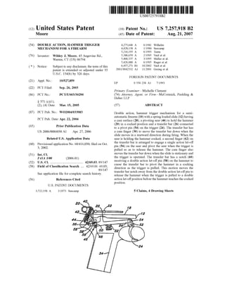
  • 1. (12) United States Patent US007257918B2 (10) Patent N0.: US 7,257,918 B2 Moore (45) Date of Patent: Aug. 21, 2007 (54) DOUBLE ACTION, HAMMER TRIGGER 4,275,640 A 6/1981 Wilhelm MECHANISM FOR A FIREARM 4,428,138 A 1/1984 Seecarnp 5,216,195 A 6/1993 Tuma (76) Inventor: Wildey J. Moore, 45 Angevine Rd., 5,386,659 A 2/1995 Vaid et a1~ Warren’ CT (Us) 06794 5,400,537 A 3/1995 Meller et a1. 5,426,880 A 6/1995 Ruger et a1. ( * ) Notice: Subject to any disclaimer, the term of this 6,457,271 B1 10/2002 Vaid et a1~ patent is extended Or adjusted under 35 2001/0042332 A1 11/2001 Gering et a1. U.S.C. 154(b) by 326 days. FOREIGN PATENT DOCUMENTS (21) Appl. No.: 10/527,859 EP 0 550 238 A1 7/1993 (22) PCT Filed: Sep. 26, 2003 Primary ExamineriMichelle Clement (86) PCT No.: PCT/US03/30290 (74) Attorney, Agent, or FirmiMcCormick, Paulding & Huber LLP § 371 (0X1), (2), (4) Date: Mar. 15, 2005 (57) ABSTRACT (87) PCT Pub- N05 W02004/033983 Double action, hammer trigger mechanism for a semi automatic ?rearm (10) With a spring loaded slide (12) having PCT Pub‘ Date: Apr‘ 22’ 2004 a cam surface (28), a pivoting sear (46) to hold the hammer _ _ _ (20) in a cocked position and a transfer bar (26) connected (65) Pnor Pubhcatlon Data to a pivot pin (54) on the trigger (24). The transfer bar has US 2006/0086030 A1 Apr. 27, 2006 a cam ?nger (30) to move the transfer bar doWn When the slide moves in a rearward direction during ?ring. When the Related US. Application Data sear is holding the hammer cocked, a second ?nger (62) on (60) Provisional application No. 60/416,030, ?led on Oct. the transfer bar is arranged.to engage a Single actio‘? let-0.1T 3 2002' pm (56) on the sear and pivot the sear When the trigger 1s ’ pulled so as to release the hammer. The cam ?nger also (51) Int CL moves the transfer bar doWn When the slide is stationary and F41A 3/00 (200601) the trigger is operated. The transfer bar has a notch (60) (52) us. Cl. ...................................... .. 42/69.03~ 89/147 receiving a double action IeF'O?C Pin (58) 011th? hammer. to (58) Field of Classi?cation Search 42/69.01,469.03' c‘i‘uselhe transferbm ‘9 PW“ the hammer. In a Cockmg 89/147’ direction as the trigger 1s pulled. This motion moves the S 1. t. ?l f 1 t h h. t transfer bar notch aWay from the double action let-oif pm to ee app 10a Ion e or Comp 6 e Seam 15 Dry‘ release the hammer When the trigger is pulled to a double (56) References Cited action let-oifposition before the hammer reaches the cocked position. U.S. PATENT DOCUMENTS 3,722,358 A 3/1973 Seecamp 5 Claims, 4 Drawing Sheets
  • 2.
  • 3. U.S. Patent Aug. 21, 2007 Sheet 2 0f 4 US 7,257,918 B2 N.A». “a, ‘N Q»Q, .0. N“.R.9“.E. w“.“W2. ‘0?v3-N» Sg 3ow
  • 4. U.S. Patent Aug. 21, 2007 Sheet 3 0f 4 US 7,257,918 B2 54 .26’ F219.3
  • 5. U.S. Patent Aug. 21, 2007 Sheet 4 0f 4 US 7,257,918 B2
  • 6. US 7,257,918 B2 1 DOUBLE ACTION, HAMMER TRIGGER MECHANISM FOR A FIREARM CROSS REFERENCE TO RELATED APPLICATIONS This application claims the bene?ts of prior ?led, US. provisional patent application Ser. No. 60/416,030, noW abandoned ?led on Oct. 3, 2002 and International Applica tion No. PCT/US2003/030290 ?led on Sep. 26, 2003. TECHNICAL FIELD This invention relates to an improved double action, hammer trigger mechanism for a ?rearm. More particularly, it relates to an improved mechanism for releasing the hammer When the trigger operates a knoWn type of transfer bar operating means to either release the hammer at a single action let-off position, or to draW back the hammer and release it When the trigger is pulled to a double action let-off position. BACKGROUND ART A ?rearm, and in particular an autoloading or automatic ?rearm, is equipped With an external hammer that can be cocked to the rear and engaged With a sear and then tripped by squeezing the trigger Which engages the sear by means of linkage releasing its engagement to the hammer (single action let-o?‘). Alternatively, the hammer can be draWn to the rear for release and ?ring by squeezing the trigger Without ?rst cocking the hammer. This is accomplished through the linkage system engaging the hammer With the trigger for the aforementioned purpose; pulling the hammer rearWard and releasing it before it can be engaged by the sear (double action let-o?‘). This invention relates to ?rearms functioning in the aforementioned manner incorporating a hammer spring, usually located in an area behind the magaZine Well in the frame and consisting of various components to accomplish the single action and double action let-offs. Historically, it is not recommended that anyone but an accomplished gun smith Work on these mechanisms as they are complicated and improper assembly or disassembly is very likely to occur. The invention addresses these issues by accomplish ing the same objectives but With basic components that anyone With an aptitude for mechanics can easily under stand. Accordingly, one object of the present invention is to provide a simpli?ed double action, hammer trigger mecha nism for a ?rearm. Another object of the invention is to provide an improved single action mechanism for releasing a sear engagement With a cocked hammer using a transfer bar connected to the trigger. Another object of the invention is to provide an improved double action let-off mechanism using a transfer bar con nected to the trigger for pulling back and releasing the hammer before the sear engages the hammer. Still another object of the invention is to provide an improved hammer trigger mechanism suitable for an auto matic or semi-automatic ?rearm of the type having a slide operated With a recoil spring for automatic or semi-auto matic ?ring. 20 25 30 35 40 45 50 55 60 65 2 DISCLOSURE OF INVENTION An improved double action, hammer trigger mechanism for a ?rearm of the type having a frame, a barrel for receiving a cartridge, a slide or bolt arranged to move longitudinally betWeen a forWard and a rearWard position With respect to the barrel, the slide or bolt de?ning a cam surface, a ?ring pin longitudinally slidable in the slide or bolt so as to strike the cartridge, a hammer arranged to pivot about a ?rst pivot point on the frame, the hammer de?ning a sear notch, spring biasing means urging the hammer toWard the ?ring pin, a spring-loaded sear arranged to pivot about a second pivot point on the frame, the sear including a lip for cooperating With the sear notch to hold the hammer cocked When the hammer is pivoted, a trigger arranged to pivot about a third pivot point on the frame, the trigger having a trigger pivot pin thereon Which is disposed so as to move in a forWard direction When the trigger is pulled, a transfer bar having a ?rst end connected to the trigger pivot pin, the transfer bar including a ?rst ?nger cooperating With the cam surface When the slide is in a forWard position, and a transfer spring biasing the ?rst ?nger toWard the cam surface, the improvement comprising a single action let-off pin disposed on the sear, the transfer bar further including a second ?nger arranged to engage the single action let-offpin and pivot the sear When the trigger is pulled so as to release the hammer When the sear is holding the hammer cocked, a double action let-off pin disposed on the hammer, the transfer bar de?ning a notch disposed to receive the double action let-off pin to cause the transfer bar to pivot the hammer in a cocking direction against the spring biasing means When the trigger is pulled to an intermediate position, the transfer bar ?rst ?nger cooperating With the slide cam surface to move the transfer bar notch aWay from the let-off pin to release the hammer When the trigger is pulled to a double action let-off position. BRIEF DESCRIPTION OF DRAWINGS The invention Will be better understood by reference to the folloWing description, taken in connection With the accompanying draWings, in Which: FIG. 1 is a side elevational draWing, partly in section, of a semi-automatic ?rearm, FIG. 2 is a styliZed side elevational draWing of the uncocked hammer trigger mechanism, FIG. 2a is an enlarged vieW of a portion ofthe mechanism of FIG. 2, FIG. 3 is a side elevational draWing of the trigger mecha nism according to FIG. 2, but With the hammer cocked for single action let-off, FIG. 4 is a simpli?ed draWing ofthe major components of the trigger mechanism commencing double action hammer rotation, FIG. 5 is a side elevational draWing of the same mecha nism at a later stage of double action movement, and FIG. 6 is a side elevational vieW of the mechanism at the double action let-off position. BEST MODE FOR CARRYING OUT THE INVENTION Referring noW to FIG. 1 of the draWing, the invention is described as embodied in a semi-automatic ?rearm of the type using a spring-loaded cartridge magaZine (not shoWn) and having a reciprocating slide 12 adapted to move from a forWard position in a rearWard direction against a recoil
  • 7. US 7,257,918 B2 3 spring (not shown) when a cartridge 14 is ?red. During the rearward movement, the shell of cartridge 14 is ejected, and during the return forward movement, a new cartridge is stripped from the magaZine and inserted into the bore of a barrel 16 in a manner well known in the art. Slide 12 is reciprocable in tracks upon a frame 18. A hammer 20 is pivotably mounted on frame 18 to strike a ?ring pin 22, which is longitudinally slidable in the slide 12 so as to strike the rear of cartridge 14. A trigger 24 is pivotably mounted in the frame and connected to push or pull a transfer bar 26. Slide 12 includes a cam surface 28, which cooperates with a ?rst ?nger 30 to raise or lower the end of transfer bar 26 when the transfer bar is pushed or pulled longitudinally by the trigger 24. The foregoing list of elements describes a construction known in the prior art. The invention relates to improvements in the linkages in the vicinity of arrow A, as illustrated in the following ?gures. Referring to FIG. 2 of the drawing, the hammer trigger mechanism is illustrated at 0° of trigger rotation and 0° of hammer rotation. Transfer bar 26 is biased upwardly by a transfer spring 32 of a suitable type located in a magaZine well 34. Hammer 20 is arranged to pivot about a pin de?ning a ?rst pivot point 36 on the frame. The hammer de?nes a sear notch 38 and is spring biased by a known type of spring biasing arrangement having a spring 40 compressed in a hammer spring well 42 by a hammer spring compression pin 44. A spring-loaded sear 46 is arranged to pivot about a pin de?ning a second pivot point 48 against a compression spring located in a sear spring well 50. A spring-loaded sear is well known and the spring is not illustrated in order not to obscure the details of the invention. The trigger 24 is arranged to pivot about a pin de?ning a third pivot point 52 on the frame, and is pivotably connected to transfer bar 26 by a trigger pivot pin 54. When the trigger 24 is pulled, the trigger pivot pin pulls the transfer bar 26 in a forward direction. In accordance with the present invention, sear 46 is equipped with a single action let-off pin 56, and hammer 20 is equipped with a double action let-olf pin 58. As shown in FIG. 2a, single action let-offpin 58 extends over the transfer bar 26 between ?rst and second ?ngers 30 and 62 respec tively, and double action let-olf pin extends over the transfer bar 26 in alignment with notch 26. Reference to the enlarged scale drawing of FIG. 2a, it is seen that the end oftransfer bar 26 de?nes notch 60 disposed to receive the double action let-olf pin 58. Further, the transfer bar 26 de?nes a second ?nger 62, which is arranged to engage the single action let-olf pin and pivot the sear when the trigger is pulled. Referring to FIG. 3 of the drawing, the hammer trigger mechanism is shown for 49.5° of trigger rotation and 60° of hammer rotation. Hammer 20 is shown cocked for single action let-off, and is being held in place by sear 46. Trigger 24 has been pulled, causing transfer bar 26 to be pulled forwardly and downwardly as dictated by the cam surface 28. The second ?nger 62 on the transfer bar is so positioned and dimensioned to engage the single action let-olf pin 56. This causes sear 46 to pivot and release hammer 20 to strike ?ring pin 22. FIGS. 4 through 6 illustrate the double action let-olf sequence. Referring to FIG. 4 of the drawing, the hammer trigger mechanism is shown at 30° of trigger rotation and 342° of hammer rotation. As trigger 24 is pulled, the ?rst ?nger 30 begins to force transfer bar 26 in a downward direction against transfer spring 32, as transfer bar 26 moves forward. The notch 60 in the transfer bar engages the double 20 25 30 35 40 45 50 55 60 65 4 action let-olf pin 58 and is starting to cock hammer 20 against the compression spring 40 in hammer spring well 42. Referring to FIG. 5 of the drawing, trigger 24 has been drawn to a 40° rotation position to further rotate the hammer to a 35° position against spring 40. Cam surface 28 contin ues to cause the transfer bar 26 to move in a downward direction against transfer spring 32. This moves notch 60 in a direction away from the double action let-olf pin 58. Finally, referring to FIG. 6 ofthe drawing at double action let-olf position, the trigger has been pulled to 55° trigger rotation, and the hammer to 492° hammer rotation. The sear has not yet engaged the hammer to hold it in a cocked position (FIG. 3). The ?rst ?nger 30 has lowered transfer bar 26 to the point where notch 60 no longer holds the double action let-olfpin 58. This releases hammer 20 to strike ?ring pin 22. The invention has been described for a semi-automatic ?rearm with a recoil slide and the cam surface disposed in the slide when the slide is in the forward position. The invention is equally applicable to a ?rearm with a bolt instead of a slide mechanism. In this case, the bolt is closed to hold the cartridge in the chamber. When the bolt is at the forward position, a cam surface similar to cam surface 28 is so disposed in the bolt to cooperate with a transfer bar. The modi?cation ofthe invention to apply to a ?rearm with a bolt will be readily understood by one skilled in the art. While there has been described what is considered to be the preferred embodiment of the invention, other modi?ca tions will occur to those skilled in the art. It is desired to secure all such modi?cations as fall within the true spirit and scope of the invention. The invention claimed is: 1. Improvement in a double action, hammer trigger mechanism for a ?rearm of a known type having a frame, a barrel for receiving a cartridge, a slide arranged to move longitudinally between a forward and a rearward position with respect to said barrel, said slide being spring-loaded in a forward direction and adapted to move in a rearward direction when the cartridge is ?red, said slide de?ning a cam surface, a ?ring pin longitudinally slidable in the slide so as to strike the cartridge, a hammer arranged to pivot about a ?rst pivot point on the frame, said hammer having a double action let-olfpin disposed thereon and also de?ning a sear notch, spring biasing means urging said hammer toward the ?ring pin, a spring-loaded sear arranged to pivot about a second pivot point on the frame, said sear including a lip for cooperating with the sear notch to hold the hammer cocked when the hammer is pivoted against said spring biasing means, a trigger arranged to pivot about a third pivot point on the frame, said trigger having a trigger pivot pin thereon that is disposed so as to move in said forward direction when the trigger is pulled, a transfer bar having a ?rst end connected to said trigger pivot pin, said transfer bar de?ning a transfer bar notch disposed to receive said double action let-olfpin so as to enable said transfer bar to pivot the hammer in a cocking direction against said spring biasing means when the trigger is pulled, and a transfer spring biasing the ?rst ?nger toward said cam surface, said improvement being characterized by: a single action let-olf pin disposed on said sear, said transfer bar including a ?rst ?nger cooperating with said cam surface when the slide is in a forward position, said transfer bar further including a second ?nger arranged to engage said single action let-olf pin and pivot the sear when the trigger is pulled so as to release the hammer when the sear is holding the hammer cocked, said transfer bar ?rst ?nger being arranged to cooperate with the slide cam surface
  • 8. US 7,257,918 B2 5 to move said transfer bar notch away from the double action let-olf pin to release the hammer When the trigger is pulled further to a double action let-olfposition When the sear is not holding the hammer cocked. 2. The improvement according to claim 1, Wherein said transfer bar has its ?rst end pivotably mounted on said trigger pivot pin and extends in a rearWard direction beneath said slide, and Wherein said ?rst ?nger extends laterally therefrom into engagement With said cam surface on the slide, said second ?nger being spaced from the ?rst ?nger to receive said single action let-olf pin therebetWeen and located to be proximate the single action let-olfpin When the hammer is cocked. 3. The improvement according to claim 1, Wherein said transfer bar has its ?rst end pivotably mounted on said trigger pivot pin and extends in a rearWard direction beneath said slide, and Wherein said ?rst ?nger extends laterally therefrom into engagement With said cam surface on the 5 10 15 6 slide and said cam surface is contoured to pivot the transfer bar aWay from the slide as the trigger is pulled, said transfer bar notch being shaped to hold said double action let-olfpin therein to move the hammer toWard a cocked position as the trigger is pulled and to release the double action let-olf pin therefrom before the hammer reaches the cocked position. 4. The improvement according to claim 1, Wherein said transfer bar extends alongside said sear and Wherein said single action let-olf pin comprises a pin disposed on said sear and extending over the transfer bar betWeen said ?rst and second ?ngers. 5. The improvement according to claim 1, Wherein said transfer bar extends alongside said hammer and Wherein said double action let-olf pin, comprises a pin disposed on said hammer and extending over the transfer bar in substantial alignment With said transfer bar notch.