Sesión de Laboratorio 3: Leyes de Kirchhoff, Circuitos RC y Diodos
•
1 gefällt mir•147 views

Laboratory session in Physics II subject for September 2016-January 2017 semester in Yachay Tech University (Ecuador). Topic covered: electricity, electrical circuits, resistances, capacitances, diodes Based on Bruna Regalado's work

Empfohlen
Weitere ähnliche Inhalte
Was ist angesagt?
Was ist angesagt? (20)
Ähnlich wie Sesión de Laboratorio 3: Leyes de Kirchhoff, Circuitos RC y Diodos
Ähnlich wie Sesión de Laboratorio 3: Leyes de Kirchhoff, Circuitos RC y Diodos (20)
Mehr von Javier García Molleja
Mehr von Javier García Molleja (20)
Kürzlich hochgeladen
Kürzlich hochgeladen (20)
Sesión de Laboratorio 3: Leyes de Kirchhoff, Circuitos RC y Diodos
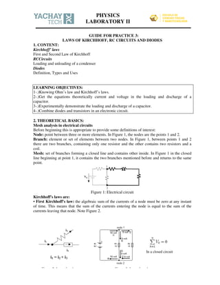
- 1. GUIDE FOR PRACTICE 3: LAWS OF KIRCHHOFF, RC CIRCUITS AND DIODES 1. CONTENT: Kirchhoff’ laws First and Second Law of Kirchhoff RCCircuits Loading and unloading of a condenser Diodes Definition, Types and Uses LEARNING OBJECTIVES: 1-.)Knowing Ohm’s law and Kirchhoff’s laws. 2-.)Get the equations theoretically current and voltage in the loading and discharge of a capacitor. 3-.)Experimentally demonstrate the loading and discharge of a capacitor. 4-.)Combine diodes and transistors in an electronic circuit. 2. THEORETICAL BASICS: Mesh analysis in electrical circuits Before beginning this is appropriate to provide some definitions of interest: Node: point between three or more elements. In Figure 1, the nodes are the points 1 and 2. Branch: element or set of elements between two nodes. In Figure 1, between points 1 and 2 there are two branches, containing only one resistor and the other contains two resistors and a coil. Mesh: set of branches forming a closed line and contains other inside. In Figure 1 in the closed line beginning at point 1, it contains the two branches mentioned before and returns to the same point. Figure 1: Electrical circuit Kirchhoff's laws are: • First Kirchhoff's law: the algebraic sum of the currents of a node must be zero at any instant of time. This means that the sum of the currents entering the node is equal to the sum of the currents leaving that node. Note Figure 2. In a closed circuit Figure 2: Law of nodes Figure 3: Law of mesh PHYSICS LABORATORY II
- 2. • Second Kirchhoff's law (Figure 3): the algebraic sum of the potential drops (voltages) in a closed mesh must be zero at any instant of time online. This means that the sum of the tensions in one direction is equal to the sum of the voltages in the opposite direction. To perform the analysis of the signs is considered: • The passive elements (which consume or absorb power) have the voltage and electric current in the same direction. These are capacitors, resistors and inductors. • The active elements (electric power sagging) have the voltage and electric current have opposite direction. These are for example the voltage generators and power sources or batteries. In mesh analysis must follow a series of steps that will arrive at the values of electric currents and potential drops in each mesh: 1- Each mesh a stream so that all have the same direction is assigned. For example in Figure 2 can be seen the currents I1, I2 and I3. 2- Currents external branches (belonging to a single mesh) will mesh current. 3- Currents internal branches (belonging to two screens) is the difference of two mesh currents. 4- Finally, it is solving the system of equations which will have as many equations as unknowns currents. RC circuits: Circuits direct current (DC or DC) containing capacitors (condensers), the current is always in the same direction but may vary over time. An RC circuit is one which is formed by a resistor and a capacitor in series. Charging a capacitor: Suppose the capacitor circuit shown in Figure 4 is initially uncharged therefore not be a current while the switch S is open. However, if the switch is closed at t = 0, the load will begin to flow, establishing a current in the circuit, and the capacitor will begin charging. During this process, the charges do not jump from one plate to another capacitor. Instead, the load is transferred from one plate to another and their connecting wires due to the electric field battery set conductors (wires), until the capacitor is fully charged. As the capacitor charges the potential difference increases. The value of the maximum load on the plates depend on the source voltage. Once the maximum load is reached, the current in the circuit is zero, since the potential difference applied to the capacitor is equal to that supplied by the source (Vi). Figure 4: RC circuits If the circuit of Figure 4 for an instant after the switch is closed and applying the laws of Kirchhoff runs you can be obtained equations charge and current as follows: Vi-Vc-VR = 0 (2nd Law of Kirchhoff) Where: Vi = voltage source; Vc: voltage at the capacitor; VR: Voltage resistance the following equations are established: − − = 0 Knowing that I= y that = − − = 0 = −
- 3. − = − = − − = Solving differential equations has the right equation: − = − It has integrand: ( − ) = − Solvingthe integral: − − = − The capacitor charging equation is obtained: ( ) = (1 − ) (Figure 5) If desired to obtain the equation of voltage on the capacitor is divided q(t)/C=Vc(t): !(") = #($ − % " &'⁄ ) Differentiating the equation q(t) the equation of the load current is obtained: )(") = # & % "/&' (Figure 6) The time it takes the voltage on the capacitor (Vc) to go from 0 volts to 63.2% of the supply voltage is given by the formula: τ=RC. Where the resistor R is in ohms, the capacitor C in milifaradios and the result will be in milliseconds. After 5τ the voltage has risen to 99.3% of its final value. The value of τ is called: TIME CONSTANT Figure 5: Charging curve of a capacitor Figure 6: Current curve versus time Discharge of a capacitor: When a capacitor is charged and you want to download very quickly enough to make a short circuit between its terminals. This operation consists of putting between them a thread of very little resistance. If one wishes to discharge the capacitor slowly, then across its terminals a resistor is placed. Turning off the power capacitor start to discharge and voltage in will decrease. The current will have an initial value of Vi/R and decrease until it reaches 0. The discharge time depends on the value of the resistor R, the capacitor C and voltage exists in the capacitor at the initial moment of discharge. The potential difference between the ends of the capacitor decreases with time t following an exponential law. When the switch is open there is a potential difference Q / C applied to the capacitor and a potential difference equal to zero applied to the resistor, since I = 0. Considering these claims the following equations applied to the circuit of Figure 4 are obtained: Figure 7: Discharge circuit of a capacitor ApplyingKirchhoff’s 2nd Law: − − + = 0 − − = 0 − − = 0 = −
- 4. Integrating: = − 1 , Solvingtheintegrall: - = − ( ) = - +.⁄ Q: Initial charge on the capacitor ( ) = − - /+. Note: the sign (-) in the current equation indicates that as the capacitor discharges, the current direction is in the opposite direction when it was charging. Figure 8: Discharge curve of a Capacitor Figure 9: Current curve versus time Semiconductor diode: The semiconductor diode is the simplest semiconductor device and can find virtually any electronic circuit. The diodes are manufactured in versions silicon (the most used) and germanium. Figure 10: Diodes Seeing the diode symbol in Figure 10 shows: A (anode), K (cathode). The diodes consist of two parts, one called N and the other called P, separated by a barrier or bonding joint call. This barrier or junction is 0.3 volts in the germanium diode approximately 0.6 volts and the silicon diode. Principle of operation of a diode: The N-type semiconductor having free electrons (electron excess) and the P-type semiconductor has free holes (absence or lack of electrons). When a positive voltage is applied to the P side and a negative side N, the electrons in the N side are pushed next P and electrons flow through the material P beyond the boundaries of the semiconductor. Likewise the holes in the material P are pushed with a negative voltage side of the material N and holes flow through the material N. In the opposite case, when a positive voltage is applied to the N side and a negative side P, electrons in the N side are pushed next N and P side holes are pushed next P. in this case the electrons in the semiconductor are not moving and therefore no current. The diode can be made to work in 2 different ways (figure 11): 1-.)Forward bias It is when the current through the diode follows the path of the arrow (the diode), or the anode to cathode. In this case the current through the diode very easily behaving almost like a short circuit 2-.)Reverse bias It is when the diode current desired circular direction opposite to arrow (arrow of the diode), or from cathode to anode direction. In this case no current through the diode, and practically behaves like an open circuit. Note: The above operation relates to ideal diode, this means that the diode is taken as a perfect element (as is done in most cases), both in forward bias and reverse bias.
- 5. Figure 11: Diode characteristic curve Specifications diodes: PIV: Peak Inverse or Inverse Voltage Peak Reverse Voltage or Rupture: The maximum peak voltage or AC that can be applied to a diode when it is reverse biased. =Forward Current: The maximum current (AC / DC) flowing through the diode when forward biased. =Forward Voltage Drop: This is the voltage drop produced by the internal resistance of the diode when forward biased =Reverse Leakage current: Is flowing through the diode when it is reverse biased. =Rupture voltage or breakdown voltage: The maximum voltage is applied to the diode should not to damage so either directly or reverse bias. 3. LABORATORY MATERIALS: Panel pins 4 mm Multimeter Diode Si-1N4007 Connecting lines (cable) Resistance 47Ω, 1W, G1 Switch, G1 Resistance 100 Ω, 1W, G1 Resistance 1k Ω, 1W, G1 Graphite resistance 4.7 kΩ, 1W, G1 Resistance 47 kΩ, 1W, G1 Resistance 470Ω, 1W, G1 Resistance 10 KΩ, 1W, G1 Power supply DC de 0 a 12V, 2A/AC: 6V, 12V, 5A Electrolytic capacitors 470 µF, 16V Stopwatch 4. EXPERIENCES: Activity 1: Implementation and verification of Kirchhoff's laws in the resolution of an electrical circuit 1) Applying Kirchhoff's laws for the theoretical values: voltage and current. 2.) Connect the circuit shown in figure.
- 6. VS= 9V R1= 10KΩ R2= 4,7KΩ Ra= 100Ω Rb= 1KΩ 3.) With the Meter measures the voltage values in every part of the electrical circuit. 4.) By Ohm's Law to determine the value of the currents flowing through the circuit Activity 2: Demonstration of the charging process of a capacitor in an RC circuit 1-.)Build the circuit shown in the figure, according to the instructions given by the teacher. Pass theswitch and startchargingthe capacitor. Where: R=10KΩ C=470µF Vi=10V 2-.)Evaluate the voltage equations (Vc) and current I(t) for each value of τ and write the corresponding equation. Activity 3: Demonstration of the process of discharge of a capacitor in an RC circuit At the end of measurements charging process proceeds to the discharge process, for which the circuit is used in the current conditions by following these steps. 1-.) Remove only one end of the voltmeter (to avoid capacitor discharge). 2.) Place the switch in off position. 3-.) Turn off the power and remove, replace at its terminals for cable. 4.) Connect the cable disconnected from the meter before and immediately pass the switch to on and start once experimental measurements capacitor discharge. Activity 4: Verification of the characteristic curve of a diode 1.)Perform the assembly shown in Figure (forward bias). Place the meter at the ends of the diode. To set the value of supply voltage measured with multimeter.
- 7. 2.) Apply the 2nd Law of Kirchhoff and get the equation that represents the diode current (i 3.) Assemble the circuit but again reverse bias (reverse the polarity of the source) NOTE: VD=Vi ∀Vi<0.65 and V data). WARNING: Working with Vi values between ( of damaging the diode. 5. DATA EVALUATION ACTIVITY 1 Complete the following tables: VS VRaTeór. VRaExp. 9V ItTeór. ItExp. ACTIVITY 2 a-.)Complete the following tables Value of0 Equation ofVc t=RC=1 0 t=2RC=2 0 t=3RC=3 0 t=4RC=4 0 b-.) Perform the following graphs Loading and unloading t(s) Vexp(V) Vteórico(V) 2 5 10 15 20 Where: Vi<5V y Vi<( R=47Ω 2.) Apply the 2nd Law of Kirchhoff and get the equation that represents the diode current (i .) Assemble the circuit but again reverse bias (reverse the polarity of the source) <0.65 and VD≅Vi∀Vi ≥0,65; Vf = 0.93 (forward voltage, manufacturer's Working with Vi values between (-5V and 5V, if it exceeds these VRbTeór. VRbExp. VR1Teór. VR1Exp. VR2Teór. Exp. I1 Teór. I1Exp. I2 Teór. I2Teór. Complete the following tables: Vc (theoric value) Equation of I(t) Perform the following graphs Loading and unloading: Vexpc vs t(s); I(t) vs t(s). Error t(s): is the time taken with the stopwatch Vi<5V y Vi<(-5V) Ω 2.) Apply the 2nd Law of Kirchhoff and get the equation that represents the diode current (iD). .) Assemble the circuit but again reverse bias (reverse the polarity of the source) Vf = 0.93 (forward voltage, manufacturer's 5V and 5V, if it exceeds these values is a risk Teór. VR2Exp. vs t(s). taken with
- 8. ACTIVITY 3 a-.) Complete the following tables: Value of 0 Equation of Vc (theoric value) Equation of I(t) t=RC=1 0 t=2RC=2 0 t=3RC=3 0 t=4RC=4 0 b-.) Perform the following graphs Loading and unloading: Vexpc vs t(s); I(t) vs t(s). c-.) According the second table, obtain the time constant τ by the slope in a linear regression involving Vexp(V) and t(s). Do NOT forget the linearization of the formula! ACTIVITY 4 a-.)Complete the following tables: Forward bias Reverse bias b-.) Construct the characteristic curve (experimental) with the data, representing the forward bias and reverse. Specific questions 1-.) Do you think that equilibrium conditions are established in an electrical circuit using Kirchhoff's laws? Justify your answer. 2-.) For what purpose resistance in the RC circuit is used? 3-.) What kind of systems are the RC circuit? 4-.) What determines the current in an RC circuit during the download process? 5-.) When you start driving through the diode? 6-.) The graphs obtained diode, indicate when the current flow is blocked? t(s) Vexp(V) Vteórico(V) Error 2 5 10 15 20 Vi (V) VD iD 0 0,25 0,50 0,65 1,00 2,00 5,00 Vi (V) VD iD 0 -1,00 -2,00 -4,00 -5,00
- 9. 5-. EXTRA HELP LITERATURE • Jerry D. Wilson, Anthony J. Buffa and Bo Lou. Physical. Pearson Prentice Hall, 2007 • Paul A. Tipler and Gene Mosca. Physics for Science and Technology, 10th edition Editorial Reverte, 2007 • Paul G. Hewitt. Conceptual Physics, 11th edition. Pearson Education, 2009 • Raymond A. and C. VuilleSerway. College physics. Cengage Learning, 2011 • Richard P. Feynman, Robert B. Leighton, and Matthew L. Sands. The Feynman Lectures on Physics "vol. 1. Addison Wesley, 1989 Links: Charging and discharging of a capacitor https://www.youtube.com/watch?v=eKhB11jPZyM Capacitors https://www.youtube.com/watch?v=EkUIUSZtdU0 Capacitor https://www.youtube.com/watch?v=YDXWACqLnmo Charging and discharging of a capacitor https://www.youtube.com/watch?v=C5lWplbeU3M