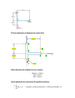
Weitere ähnliche Inhalte Mehr von Jesthiger Cohil (20) Kürzlich hochgeladen (20) 1. Primero dibujamos el diagrama de cuerpo libre:
!
0,28!!
!!
0,18!!
!!
!
0,10!!
!
!
!
30°
150!!
Ahora llevamos las medidas de mm a metros:
ne Solutions Manual Organization System
280 𝑚𝑚 = 0,28 𝑚
180 = 0,18 𝑚
100 = 0,10 𝑚
on 19.
m:
!!
Ahora aplicando las ecuaciones de equilibrio tenemos:
(a) From free-body diagram of lever BCD
ΣM C = 0: TAB ( 50 mm ) − 200 N ( 75 mm ) = 0
𝑀! = 0: − 𝐴 0,18 + 150 sin 30 0,10 + 150 cos 30 0,28 = 0
∴ TAB = 300
(b) From free-body diagram of lever BCD
ΣFx = 0: 200 N + Cx + 0.6 ( 300 N ) = 0
∴ C x = −380 N
or
C x = 380 N
2. 21.
OS: Complete Online Solutions Manual Organization System
COSMOS: Complete Online Solutions Manual Organization System
pter 4, Solution 19.
𝑨 =
Chapter 4, Solution 19.
e-Body Diagram:
150 sin 30 0,10 + 150 cos 30 0,28
= 𝟐𝟒𝟑, 𝟕𝟒 𝑵
0,18
(a) From free-body diagram of lever BCD
Free-Body Diagram:
ΣM C = 0: TAB ( 50 mm ) − 200 N ( 75 mm ) = 0
(a) From free-body 𝑜 𝑨lever𝟐𝟒𝟒 𝑵 →
diagram of = BCD
∴ TAB = 300
ΣM C = 0: TAB ( 50 mm ) − 200 N ( 75 mm ) = 0
⎛ 2.4 in. ⎞
(b) From
−⎜
⎟ A − (0.9 in.)Fsp = 0 free-body diagram of lever BCD
Βx = 0 :
⎝ cosα ⎠
∴ T = 300
ΣFx = 0: 0: 243,74 +300 N ) = 0 30 + 𝐷 = 0 AB
𝐹! = 200 N + Cx + 0.6 ( 150 sin
!
8
(b) From free-body diagram of lever BCD
Fsp =
lb = kx = k (1.2 in.)
∴ C x = −380 N
or
C x = 380 N
cos 30°
ΣFx = 0: 200 N + C + 0.6 ( 300 N ) = 0
𝑫 𝒙 = 0: C y + − 150 xsin 30
ΣFy= −243,74 0.8 ( 300 N ) = 0 = −𝟑𝟏𝟖, 𝟕𝟒 𝑵
∴ C x = −380 N
or
k = 7.69800 lb/in.
k = 7.70 lb/in. ▹ C x = 380 N
∴ C y = −240 N
or
C y = 240 N
ΣFy = 0: C y + 0.8 ( 300 N ) = 0
or
Then
8 lb ⎞
( 3 lb ) sin 30° + Bx + ⎛
⎜
⎟=0
⎝ cos30° ⎠
and Then
Bx = −10.7376 lb
0:
− ( 3 lb ) cos 30° + B y = 0
0:
C =
𝐹! = 0: 𝐷2 − 150 cos 30 = 0
!
2
2
2
C x + C y C = 380 ) N ( 240 ) = 449.44240 N
∴ = y ( −240 +
or
Cy = N
C
𝑫 ⎛ = ⎞ 150 cos 30 = 𝟏𝟐𝟗, 𝟗𝟎𝟒 𝑵
2
2
− 240 ⎞
2
C 1 y 2 = C y =⎛
) 32240 )
θ = tan −=𝒚⎜ C x⎟ + tan −1 ⎜ ( 380⎟ =+ ( .276° = 449.44 N
⎜C ⎟
⎝ − 380 ⎠
⎠
⎛ Cy ⎞
⎛ − 240 ⎞ C = 449 N
or = 32.276°
32.3° ▹
and
θ = tan −1 ⎜ ⎟ = tan −1 ⎜
⎟
⎜ C!⎟
!
⎝ − 380 ⎠ ! + 129,904 ! = 𝟑𝟒𝟒, 𝟐𝟎 𝑵
x ⎠
By = 2.5981 lb 𝑃𝑜𝑟 𝑙𝑜 𝑡𝑎𝑛𝑡𝑜: 𝑫 = 𝐷! + ⎝ 𝐷! = −318,74
or
or C = 449 N
32.3° ▹
2
2
= ( −10.7376 ) + ( 2.5981) = 11.0475 lb, and
𝐷
129,904
2.5981
= tan −1
= 13.6020°
10.7376
⎝
x
𝑎𝑑𝑒𝑚𝑎𝑠 𝜽 = tan!!
!
𝐷!
= tan!!
B 𝟑𝟒𝟒 𝑵
𝑜 𝑫 = = 11.05 lb
s: Statics and Dynamics, 8/e, Ferdinand P. Beer, E. Russell Johnston, Jr.,
Clausen, David Mazurek, Phillip J. Cornwell
mpanies.
Mechanics for Engineers: Statics and Dynamics, 8/e, Ferdinand P. Beer, E. Russell Johnston, Jr.,
. Eisenberg, William E. Clausen, David Mazurek, Phillip J. Cornwell
7 The McGraw-Hill Companies.
Vector Mechanics for Engineers: Statics and Dynamics, 8/e, Ferdinand P. Beer, E. Russell Johnston, Jr.,
Elliot R. Eisenberg, William E. Clausen, David Mazurek, Phillip J. Cornwell
© 2007 The McGraw-Hill Companies.
−318,74
13.60° 𝟐𝟐, 𝟐°
𝜽= ▹
= −𝟐𝟐, 𝟏𝟕𝟒°
3. Primero dibujamos el diagrama de cuerpo libre:
!!
!!
2!
+
!
os
!c
!!
!
!!
!
!!
!!
!!
!!
OS: Complete Online Solutions Manual Organization System
!
!
pter 4, Solution 19.
e-Body Diagram:
Ahora aplicando las ecuaciones de equilibrio tenemos:
(a) From free-body diagram of lever BCD
ΣM C = 0: TAB ( 50 mm ) − 200 N ( 75 mm ) = 0
𝑀! = 0: 𝑇 2𝑎 + 𝑎 cos 𝜃 − 𝑇𝑎 + 𝑃𝑎 = 0
∴ TAB = 300
(b) From free-body diagram of lever BCD
ΣFx = 0: 200 N + Cx + 0.6 ( 300 N ) = 0
∴ C x = −380 N
or
C x = 380 N
ΣFy = 0: C y + 0.8 ( 300 N ) = 0
∴ C = −240 N
or
C = 240 N
4. Chapter 4, Solution 19.
Free-Body Diagram:
(a) From free-body diagram of lever BCD
𝑷
ΣM C = 0: TAB ( 50 mm ) − 200 N ( 75 mm ) = 0
𝑻=
𝟏 + 𝐜𝐨𝐬 𝜽
(𝐼)
∴ TAB = 300
(b) From free-body diagram of lever BCD
ΣFx = 0: 0: 𝐶 x− 0.6 ( 300 = )0= 0
𝐹! = 200 N + C + 𝑇 sin 𝜃 N
!
∴ C x = −380 N
or
C x = 380 N
COSMOS: Complete Online Solutions Manual Organization System
𝑪 = C + 0.8 ( 300 N )
ΣFy = 𝒙0: 𝑻y 𝐬𝐢𝐧 𝜽 (𝐼𝐼) = 0
∴ C y = −240 N
C y = 240 N
or
De (I)
2
2
Chapter 4, Solution 19. en (II) se tiene que: C = Cx + C y = ( 380 )2 + ( 240 )2 = 449.44 N
Then
Free-Body Diagram:
𝑷 𝐬𝐢𝐧 𝜽
⎛C ⎞
⎛ − 240 ⎞
y
𝑪𝒙 =
θ = tan −1 ⎜ ⎟ = tan −1 (𝐼𝐼𝐼)= 32.276°
⎜ 𝟏 +⎟ 𝐜𝐨𝐬 𝜽 ⎜ − 380 ⎟
⎠
⎝
⎝ Cx ⎠
(a) From free-body diagram of lever BCD
and
or C = 449 N
ΣM C = 0: TAB ( 50 mm ) − 200 N ( 75 mm ) = 0
𝐹! = 0: 𝐶! + 𝑇 + 𝑇 cos 𝜃 − 𝑃 = 0
32.3° ▹
∴ TAB = 300
(b) From free-body diagram of lever BCD
ΣFx = 0: 200 N + Cx + 0.6 ( 300 N ) = 0
𝑪 𝒚 = 𝑷 − 𝑻 𝟏 + 𝐜𝐨𝐬 𝜽 (𝐼𝑉)
∴ C x = −380 N
C x = 380 N
or
ΣFy
De (I) en (IV) se tiene que:= 0: C y + 0.8 ( 300 N ) = 0
∴ C y = −240 N
C y = 240 N
or
Then
2
2
2
C = 𝐶C x= 𝑃y− 𝑃 ( 380 )cos (𝜃 = 0= 449.44 N
+ C 2 = 1 + + 240 )
!
and
⎛ Cy ⎞
⎛ − 240 ⎞
θ = tan ⎜ ⎟ = tan −1 ⎜
⎟
⎟
⎜ 𝑪 𝒚 = 𝟎 , 𝐶 = =!32.276°
⎝ − 380 ⎠ 𝐶
⎝ Cx ⎠
1 + cos 𝜃
−1
or C = 449 N
32.3° ▹
𝑷 𝐬𝐢𝐧 𝜽
𝑪 =
(𝑉)
𝟏 + 𝐜𝐨𝐬 𝜽
𝐶𝑜𝑚𝑜 𝜃 = 60° 𝑠𝑒𝑔𝑢𝑛 𝑒𝑛𝑢𝑛𝑐𝑖𝑎𝑑𝑜
De (I) se tiene que:
𝑻=
𝑃
𝑃
𝑃
𝟐
=
=
=
1
1 + cos 𝜃
1 + cos 60
𝟑
1 + 2
Vector Mechanics for Engineers: Statics and Dynamics, 8/e, Ferdinand P. Beer, E. Russell Johnston, Jr.,
Elliot R. Eisenberg, William E. Clausen, David Mazurek, Phillip J. Cornwell
© 2007 The McGraw-Hill Companies.
𝑷
5. Ahora De (V) se tiene que:
𝑪 =
𝑃 sin 𝜃
𝑃 sin 60
𝑃 0,87
=
=
= 𝟎, 𝟓𝟖 𝑷
1
1 + cos 𝜃
1 + cos 60
1 + 2