
Empfohlen
Weitere ähnliche Inhalte
Was ist angesagt?
Was ist angesagt? (20)
Andere mochten auch
Ähnlich wie Pipeline Welding
Ähnlich wie Pipeline Welding (20)
Kürzlich hochgeladen
Kürzlich hochgeladen (20)
Pipeline Welding
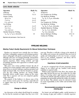
- 1. Previous Page Lens shade selector Operation Shade No. Operation Shade No. Soldering 2 Nonferrous Torch Brazing 3 or 4 Gas Tungsten-Arc Welding Oxygen Cutting Gas Metal-Arc Welding up to 1 in. 3 or 4 He, %2, %, %2 in. electrodes 11 1 to 6 in. 4 or 5 Ferrous 6 in. and over 5 or 6 Gas Tungsten-Arc Welding Gas Welding Gas Metal-Arc Welding up to % in. 4 or 5 Xe, %2, %, %2 in- electrodes 12 % to X in. 5 or 6 Shielded Metal-Arc Welding X in. and over 6 or 8 /16, /32, in. electrodes 12 Shielded Metal-Arc Welding /16, % in. electrodes 14 /16, %2, %, %2 in. electrodes 10 Atomic Hydrogen Welding 10 to 14 Carbon-Arc Welding 14 Reprinted with permission—Tube Turns, Inc. PIPELINE WELDING Meeting Today's Quality Requirements For Manual Vertical Down Techniques Pipelines are inspected more critically than ever before, years ago. Therefore, it will take a change in the attitude of and today's radiographic equipment and techniques produce the welders and everyone else involved if this new level of clearer radiographs with greater sensitivity than in the past. quality and workmanship is to be met. In turn, a commit- Although codes have not changed drastically, interpretation ment to new methods, equipment, and theory will be standards have been upgraded. The combination of more required by all concerned. rigorous inspection, better testing methods, and high acceptability standards often approaches an attitude requir- Importance of joint preparation ing zero defects. This poses some serious problems because the job of It must be recognized that all joint preparation details welding cross-country pipelines under typical conditions has (Figure 6) are critical and any variation could directly always been an extreme challenge requiring specialized and contribute to rejected welds. highly developed skills. Now that the demands are greater, Without good cooperation from those who prepare the even the best welding operators are having trouble. pipe edges and the line-up crew, the welder has very little Rejectable defects usually require cutting out the entire chance of meeting today's rigid inspection requirements. weld. This is expensive and can cost competent pipeline Too often the attitude exists that variations in fit-up and joint welders their jobs. preparation are permissible and that the welder can compen- The purpose of this bulletin is to discuss some of the sate for them. This attitude cannot be tolerated. It puts more common reasons given for rejecting a pipeweld and too much responsibility on the welder and inevitably leads to suggest what may be done to correct some of these to rejects. conditions. Recommended procedures for properly Change in attitude cleaning pipe Any discussion on this subject should begin by accepting For lowest cost and highest quality, careful attention to the fact that the standards are higher than they were a few the cleaning of pipe joint surfaces is critically important.
- 2. Courtesy of Pipeline & Gas Industry. Today's pipe welders face pipe that may be covered with a Internal undercut variety of coatings; these include primers, epoxy, tar, paper, varnish, rust, scale, or moisture. See Figures 1 through 5 for x-rays of the various defects While joint cleanliness is important in all welding, it is that can cause rejects. Of these, one of the most common especially so in the root pass of pipe. Even a thin film of and troublesome is internal undercut (undercut on the contaminants, which may be difficult to see with the naked inside of the pipe). This is understandable because it occurs eye, may be present. Failure to recognize and properly clean on the quot;blind sidequot; and the operator cannot see it happening. joints can result in a hollow bead or other welding defects. Consequently, he cannot immediately do anything to correct Follow these instructions to minimize costly defects: it. To make matters worse, he seldom gets a chance to see the x-ray negative or the actual weld itself. All of this makes 1. Remove all moisture and condensations of any type it difficult for him to correct the situation. prior to welding. The joint must be completely dry. 2. Clean BOTH ends of the pipe INSIDE AND OUT to Undercut may be the direct result of poor joint preparation remove traces of paint, rust, scale, oil, epoxy, or organic or fit-up. If the joint does not conform to the details specified materials. The area to be cleaned should extend at least in the established procedures (see Figure 6), every reasonable 1 inch (25 mm) from the end of the bevel (per ANSI/ effort should be made to correct it before starting to weld. AWS D10.11-80 Page 1) on both the INSIDE and Internal undercut will tend to occur if: OUTSIDE surfaces. 1. The root face (Land) is too small. 3. A recommended method for cleaning in the field as 2. The root opening is too large. described above is the use of a heavy duty straight shaft 3. If a severe high-low condition exists. grinder with a rubber expanding wheel and a carbide 4. The current is too high. coated sleeve. The small shaft and reduced overall weight allows easy access to the inside and outside When any undesirable variation occurs in the joint surfaces of the pipe. preparation, the normal reaction is to compensate for it by
- 3. Figure 1. Radiograph of internal undercut. This defect may be intermit- tent or continuous (Figure 2) and either on one side or both sides of the weld centerline. WHEN RADIOGRAPHS ARE INDICATIVE OF POOR WORKMANSHIP, BEST RESULTS CAN BE OBTAINED BY SHOWING THE RADIOGRAPHS TO THE WELDER SO THAT HE OR SHE CAN UNDERSTAND WHAT HE OR SHE IS DOING WRONG AND CORRECT IT. Figure 2. Radiograph of internal undercut and the lack of penetration that tends to occur at a stop and start. Figure 3. Radiograph of lack of penetration on the stringer bead appears as a single, straight, dark line. Figure 4. Radiograph of unfilled wagon tracks. Distinguishing between this defect and internal undercut required skill and experience.
- 4. Figure 5. Radiograph of porosity. juggling the root spacing. Within limits, this can be fairly A skillful line-up crew can be helpful in juggling the root effective. For example: spacing to bring about the most favorable results, but this has limitations. And it is at best a poor substitute for a uniform Condition Change in Root Spacing and consistent joint preparation. Land too small. Decrease root spacing. Land too large. Increase root spacing. Internal chamfer High-low condition. Decrease root spacing. Bevel too small. Increase root spacing. It is important to remove any burr or overhang on the inside edge of the pipe after the root face has been machined Alternate StfinQtf Ctoctrod*^ Current* Bead P/ocadur« Past in. (mm) AmptDC(+)» Amp§OC(-)» Stringer Bead Vi (3.2) 01 90 — 120 85—115 or 6 / M (4.Op 140 — 165<4» 115—140 Hot Pass »/»(4.0) 160 — 185 Fiiis and Stripper * » (4.8) 160 — 190 3 Cap Pass /i6 (4.8) 150 — 180 ( 1 > Fleetweld 5 P + , Shield-Arc* HYP or 7 0 + suggested depending upon the pipe steel requirements and contractor specifications. w The ideal current should be selected from within the range shown. In general, the best quality will be obtained by operating at the lower end of the range. Hot pass currents up to 200 amps are often used but cause early coating breakdown and larger stub losses. * Use V (3.2 mm) diameter electrode for stringer beads when the wall thickness is .250quot; (6.35 mm) or less and when the gap is too small to permit use of the Vsquot; (4.0 mm) size [Vtquot; (3.2 mm) diameter electrode should also be used on other passes when the wall thickness is .250quot; (6.35 mm) or less; however,»/»quot; (4.0 mm) diameter can also be used on fill and cap passes on .250* (6.35 mm) wall]. 4 <> weld stringer bead at 23-25 arc volts and 10-16 in/min arc speed. Measure arc voltage between the pipe and electrode holder. 151 Polarity — DC ( - ) (negative polarity) should be used for stringer bead welding when burn-through, internal undercut and hollow bead defects are a problem. These problems generally occur on thin wall pipe steels containing over . 1 % silicon. Lower currents are used with D C ( - ) which helps to reduce these problems. Travel speeds with D C ( - ) will be equal to travel speeds with DC(+). Root Face (Land) Hot pass and all other passes should be run DC{+) (positive polarity). Root Opening (Gap) Welding D C ( - ) (negative polarity) on the stringer bead will not be harmful to either mechanical or metallurgical properties. General Guidelines for Power Source Adjustment (SA- and SAE Machines) In general, the quot;Current Rangequot; or quot;Current Controlquot; switch (whether a tap or continuous control), should always be set as low as possible to get the current wanted, and the quot;Fine Current Adjustmentquot; or quot;Job Selector control (which controls open circuit voltage) should be set as high as possible. It is usually better to set this control (for OCV) at the mid-point or higher for best arc stability and fewest popouts. Figure 6. Recommended joint preparation and typical procedures—operate within these tolerances to help ensure When using a Lincoln SA-250 engine driven power source, it will normally be necessary good-quality welds. to set the quot;Current Range Selectorquot; tap switch one position lower than used on a Lincoln SA-200 power source to get the same operating characteristics.
- 5. (or ground). However, this clean-up operation should never produce an internal chamfer. A condition such as this is almost certain to result in quot;internal undercutquot; (Figure 7). See Recommended Procedures for Cleaning Pipe on the previous page. Undercut vs. welding current Figure 7. An internal chamfer will tend to leave an unfilled area on one or both sides of the stringer bead. On the x-ray this will Excessive current produces internal undercut. Further, be interpreted as internal undercut. the incidence of internal undercut is more prevalent in the 4-6-8 o'clock portions of the pipe. In this bottom area it is possible to use a considerably higher current than is Assuming that the joint preparation is correct, the keyhole necessary without getting burn-through, and this results in size is a function of current, electrode angle, and pressure. overheating and undercutting. Knowing this, it would appear The current should be quot;fine tunedquot; to produce a small to be a simple matter to specify an ideal current that would keyhole when the electrode is dragged lightly using the not give undercut. However, this is extremely difficult normal electrode angle. If minor variations occur in the because of the many variables of the many interrelated keyhole size (for any reason), the electrode angle and factors. pressure can be manipulated to maintain the proper keyhole A recommended current range is given in Figure 6, but it size (Figure 9). is necessarily rather broad to cover all reasonable variations. In general, a keyhole that is about Vgquot; (3.2 mm) in length From a practical standpoint, the correct current should be is ideal; if it becomes 5Z32quot; (4.0 mm) or longer, undercut and determined by starting within the recommended range and windows are imminent. then quot;fine tuningquot; to get precisely what quot;feels goodquot; and Frequently, a good inside bead is obtained without produces the required results. This final current value will having a visible keyhole. For example, at a tight spot, vary slightly from one operator to another and with different the keyhole may disappear and the arc goes quot;inside the pipe materials, diameters, wall thickness, etc. pipe.quot; With the proper manipulative skill, this condition is Because of inaccuracies in ammeters, the effect of arc tolerable and a good inside bead will be obtained. However, voltage on current, the inability to accurately read a bobbing when it is done in this manner, the welder is largely ammeter, etc., it is impractical to hold to an arbitrary current dependent on the sound of the arc inside the pipe. A small, value. For the accomplished stringer bead welder, the visible keyhole is easier to work with and is a much more selection of the ideal current is not too difficult—but he will controllable condition. be doing it primarily by quot;feel and touch.quot; Significance of arc voltage Keyhole size vs. current and undercut It is recommended that meters be used since a fairly good To get a good inside bead it is highly desirable to maintain correlation can be established between the arc voltage and a small, visible keyhole at all times. If the keyhole is allowed the keyhole size. For example, under controlled conditions, to get too big, it will result in internal undercut and/or an ideal keyhole size is consistently accompanied by an arc windows (Figure 8). voltage of no more than 25 volts. When keyhole size is LARGE KEYHOLE SMALL KEYHOLE EXCESSIVE CURRENT GOOD PROCEDURE POOR PROCEDURE Figure 8. Maintaining a small keyhole will help assure a good inside bead. The larger keyhole at the right is almost certain to give internal undercut and/or windows.
- 6. ONE OF THE PRIME OBJECTIVES OF THE STRINGER BEAD CREW SHOULD BE TO PROVIDE A GOOD, STOUT STRINGER WITH AS MUCH THROAT AS POSSIBLE. Angle varied to Angle varied to increase penetration decrease penetration Normal Angle Electrode pressure may Electrode pressure may also be increased and be decreased and speed speed decreased. increased. Figure 9. The penetration and keyhole size can be effectively controlled by varying the electrode angle as shown—if the joint preparation is uniform. increased by increasing current, increasing the gap, changing the welder (see Figure 9). In an extreme case, a second pair the electrode angle, etc., the arc voltage increases to 26-28 of hands may be required to adjust the current up or down volts. This is reasonable because the arc voltage reflects arc on a signal from the welder. This requires a good commu- length. At the higher arc voltages, internal undercut and nication system and a well-coordinated effort to avoid wagon tracks may occur. overshooting or undershooting the current. In some cases, The same arc voltage numbers quoted above may not this becomes a survival technique to make up for other occur in all instances. However, it is readily apparent that undesirable variations. there is a dependable correlation between keyhole size and arc voltage. A maximum tolerable arc voltage can be Undercut—real or imaginary? determined by experimentation. It should be further noted that this arc voltage is If visual inspection were practical for determining internal determined while welding and it should not be confused undercut, it would be easy to accurately determine its with the open circuit voltage. Also, it can be affected by the presence and severity. However, this is not the case. welding technique; changes in electrode angles and drag Radiography is the judge of internal conditions, and this techniques should not be allowed to cloud the issue. has led to many questionable interpretations. If internal undercut is present, it will show up on the film as a very narrow, dark line immediately adjacent to the stringer Varying current/varying gap bead—on one or both sides. The darkness of the line will vary with the depth of the undercut (Figures 1 and 2). Greater root penetration naturally occurs at the top and Proper identification of undercut is sometimes difficult bottom portions of the pipe, and least penetration tends to because its location is directly in line with the quot;wagon trackquot; occur at the sides. This being the case, it would be desirable area (Figure 4). Distinguishing one from the other may be to alter the root spacing accordingly, but this obviously is not difficult. practical. It should also be noted that a condition which Correct interpretation of internal undercut may be further permits maximum spacing on top and bottom and minimum complicated by the fact that a quot;stoutquot; inside bead will stand spacing on the sides is not tolerable. out clearly (lighter on the film) against the adjacent area, Assuming a uniform gap all the way around, the ideal which is thinner and therefore darker. The thinner, darker condition would be to vary the current as the weld area will be further darkened by the presence of any fairly progresses from 12 to 6 o'clock to compensate for the deep, widely spaced surface ripples in the cap pass. The net changes in penetration due to position. Instead, penetration effect is to produce a dark shading in the area where internal changes are usually controlled by the manipulative skills of undercut might occur.
- 7. It is the responsibility of the stringer bead crew to minimize wagon tracks and the responsibility of the hot pass crew to burn them out. This is normally done with 5/32quot; (4.0 mm) electrode at about 175-180 amps. The secret in melting out wagon tracks lies primarily in the skill of the hot pass crew and the penetration factor of the electrode. The Figure 10. Any deep surface ripples located directly above a majority of the hot pass men use a rapid stitching technique point adjacent to the inside bead will contribute to a dark that exposes the wagon track momentarily and permits them shading of the film at this area. This has been misinterpreted by some as internal undercut. to direct the arc into the undercut area and melt them out. Condition Results Bevel too small (Figure 12). Increases depth of W.T. Root spacing (gap) too small. Increases depth of W.T. Figure 11. quot;Wagon tracksquot; are located on either side of the Current and/or speed too high. Increases depth of W.T. stringer bead. Although this darker area is considerably wider than any The depth of the wagon tracks may be affected by the undercut, it has been mistaken for undercut and resulted in following: cutting out good welds. Normally, a quot;stoutquot; inside bead is In extremes, it may be necessary to use a grinder to open up considered good, but in this instance, the stouter the bead, the sidewalls to minimize deep quot;wagon tracksquot; or, if they do the darker the adjacent area would appear (Figure 10). occur, to grind the stringer to eliminate the high peaked center (Figure 13). In all cases a %2 quot; (4.0 mm) thickness disc grinder should be used to grind root beads on all pipe Wagon tracks from 12quot; (304.8 mm) up irrespective of wall thickness [a quot; (3.2 mm) disc grinder will grind the center and roll the sides It is not possible to completely eliminate the sidewall over on the wagon track unless side pressure is applied]. This undercut produced by the stringer bead. This condition is will make it easier to melt them out. generally referred to as quot;wagon tracksquot; (Figures 4 and 11). Tends to trap slag Figure 12. The depth of the wagon tracks will vary inversely with the bevel angle. Before grinding After grinding A narrow bevel or tight gap may require grinding as per dotted line. Figure 13. A disc grinder, if used with restraint, can be helpful in correcting the condition shown above.
- 8. The electrode should be centered in the joint and not changed unless the bead wanders off to one side or the other. Changing the angle will bring it back. Figure 14. The correct angle can only be determined by observing the shape and location of the bead. If the bead drifts to one side for any reason, it will leave a deep undercut on the opposite sidewall. Tilting the electrode just a few degrees toward the undercut side will straighten the bead up. This change must take place rapidly if the correct bead placement is to be maintained. If the stringer bead tends to wander to one side or the Hot pass and all other passes should be run DC(+) other, it will leave a deep undercut on the shallow side. This (positive polarity). condition should be corrected immediately by changing the Welding DC( —) (negative polarity) on the stringer bead electrode angle (Figure 14). will not be harmful to either mechanical or metallurgical properties. Hollow bead or wormhole porosity may also be caused by poor joint preparation and/or cleanliness. See Recom- The hollow bead mended Procedures for Properly Cleaning Pipe. The stringer bead defect shown in this sketch is known by several names including the hollow bead, vermicular Filler, stripper, and cap porosity, and wormhole porosity. Its length varies from a fraction of an inch to several inches. Radiography exposes In general, there is little fault found with the fillers, the presence of the problem clearly. strippers, and caps. Most of this welding today is being done with 3/16quot; (4.8 mm) Shield-Arc® HYP or 70+ at 160-180 amps, and the results have been excellent. A reasonably competent crew of firing line welders armed with FW5P+, HYP, or 70+ can do a very fine job of finishing the weld if the stringer and hot pass crew have been doing their work properly. The size and consistency of the final weld will have its Vermicular porosity occurs most readily when welding influence on the x-ray radiograph. Thus, the firing line high silicon pipe—generally above .10% silicon. It is welders should be encouraged to produce a cap pass that is aggravated by excessive travel speeds and high currents. as uniform as possible with neatly stitched close ripples and Welding the stringer bead with %2quot; (4.0 mm) electrode at as much reinforcement as required. 130-165 amps DG(+) and 12 to 14 in/min (0.3 to 0.4 m/min) travel speed minimizes its occurrence. DC(—) (negative polarity) should be used for stringer bead welding when Welding cracks burn-through, internal undercut and hollow bead defects are a problem. These problems generally occur on thin wall Since the advent of the higher tensile pipe steels (5LX 52, pipe and on pipe steels containing over .1% silicon. Lower 60, 65, 70 etc.), it has been necessary to exercise better currents can be used with DC(—), which helps to reduce procedural control to eliminate the possibility of weld and these problems. Travel speed with DC(—) will be equal to heat-affected zone (HAZ) cracks. To do this effectively, all of travel speeds with DC(+). the following factors must be controlled.
- 9. 1. Joint preparation and root spacing must be as specified 9. Remove slag from each bead by power wire brushing. in the approved procedure. (See Figure 6.) Grinding should not be necessary except possibly to 2. Hi-Low conditions must be held to a minimum. clean up a lumpy start or humped up center or perhaps 3. Weld 5LX70 with Shield-Arc® 70+. Weld 5LX65 and to improve a crater condition. Note: Grinding of the lower with Shield-Arc HYP or Fleetweld 5P+. Fleet- stringer bead should be done with a 5Z32 quot; (4.0 mm) disc. weld 5P+ is recommended for all stringer beads when Excessive grinding can be detrimental. lower hardness is a consideration. Lower stringer bead 10. Weld stringer beads with two or more persons welding hardness will result in improved resistance to HAZ on opposite sides to equalize stress. Use three welders cracking. on 20-30quot; (508-762 mm) pipe, and four welders on 4. The need for preheat varies considerably between larger pipe. applications. Cracking tendencies increase with higher carbon and alloy content, thicker pipe wall and diameter (faster quench rate), and lower ambient temperature. Preheat cold pipe to at least 70 0 F Recommended pass (21°C). Preheat to as much as 300 0 F (149°C) may be sequence required to slow the quench rate and prevent cracking when welding high-strength, large-diameter, or heavy-wall pipe. Specific preheat requirements must be determined for each situation based on these Start considerations. Stop 5. Ideally the line-up clamp should not be removed nor should any movement of the pipe take place until the stringer bead is 100% completed. Any movement of the pipe could cause a partially com- 11. Start the hot pass immediately after completion of the pleted stringer bead to be overstressed and to crack. stringer—always within 5 minutes. At least two hot The tendency for such cracking varies with the pass welders should be used on each joint, and to put chemistry of the pipe, its diameter and wall thickness, this pass in as soon as possible after the stringer bead and its temperature. Under favorable conditions it it may require a total of four hot pass welders leap may be possible to remove the line-up clamp with frogging each other to keep up. as little as 60% of the stringer bead completed, but 12 Minimize the wagon tracks—this area is highly vul- this should be done only when it has been clearly nerable to cracking until the hot pass is completed demonstrated that this practice does not cause cracks (Figure 15). to occur. 6. After removal of the line-up clamp, the pipe must be gently and carefully lowered on skids. 7. Use only enough current on the stringer to get a good inside bead and travel slowly to get the maximum weld cross section. 8. Restrict lack of penetration on the inside bead at tie-ins Figure 15. Cracks tend to occur at the area indicated on one side or the other of the stringer bead. This could eventually to 1Z4quot; (6.4 mm) or less. Use a disc grinder to improve propagate up through the weld. A properly controlled proce- this situation on starts and stops only. dure and good workmanship can eliminate this condition. Reprinted with permission—Lincoln Electric Co.
- 10. Next Page How many welds will the average welder make per hour? Where stringer beads have been run, the average welder On large diameter pipe where wall thickness has been can complete about 140 inches of weld per hour on ordinary increased, welders average about 100 inches of completed -inch wall line pipe. To find the average number of welds weld per hour. per hour, divide the circumference of the pipe into 140. Example. How many welds per hour will a welder 140 N = -—where circumference(C) = pipe diameter complete on 30-inch line pipe if the stringer beads have been run? in inches times 3.14 Example. How many welds per hour will a welder complete on 1Z4 -inch wall 10% -inch line pipe, if the stringer beads have been run? 1 0 0 1 0 0 M 1 1 U U 1 1 IJ 140 N = = N = (30X3li) 945 = L 1 W d d S PCT h U r ° °r U WeWS (10.75)(3.14) per 10-hour day 33.76 N= 4.15 welds per hour or about 42 welds per 10-hour day. How much welding rod is required for a mile of schedule 40 pipeline? For 40-ft joints: Rule. For 40-foot joints of schedule 40 pipe, multiply the nominal pipe diameter by 221^; the answer is pounds of 40 225 x — = 300 Ib. per mile for 30-ft joints. electrode per mile of pipeline. The rule is based on standard weight (schedule 40) Example. 6-in. pipe: pipe and the usual number of passes, which varies from 6 x 221A = 135 Ib. per mile two for small pipe up to four for 16 in.; larger pipe is usually thinner wall. The rule includes an allowance for wastage. Example. 10-in. pipe, 30-ft joints: 10 x 221A = 225 Ib. per mile How many pounds of electrodes are required per weld on line pipe? Divide the nominal pipe size by 2 and multiply the result Pounds of electrode = — x .25 = 1.25 Ib. per weld. by one-fourth pound. ,Z N Pounds of electrode = — x 0.25 Example. How many pounds of electrode will be used per weld on 24-in. line pipe? Example. How many pounds of electrode will be used Solution. Pounds of electrode = 12 x0.25 or 3 Ib. per weld on 10-in. line pipe? per weld.