Understanding Condensate Pumps on a Steam Distribution System

The primary application for the condensate pump is pumping condensate from a process application or condensate collection area back to the condensate return system. Additional pumping units can be used for increased capacity or pump redundancy in case of failure. Simplex, Duplex, Triplex and Quadraplex condensate pumping systems are available. A Pump-Trap Combination is used when draining condensate from a single piece of heat transfer equipment whose steam flow is being controlled with a modulating type valve. When a modulating valve controls the flow of steam to a heat exchanger, a stall condition can develop. Stall occurs when the modulating valve closes and steam pressure downstream of the valve is unable to push the condensate into the return line and it backs up into the heat exchanger. A pump-trap combination will eliminate this problem.

Empfohlen
Weitere ähnliche Inhalte
Was ist angesagt?
Was ist angesagt? (20)
Andere mochten auch
Andere mochten auch (17)
Ähnlich wie Understanding Condensate Pumps on a Steam Distribution System
Ähnlich wie Understanding Condensate Pumps on a Steam Distribution System (20)
Mehr von Ives Equipment
Mehr von Ives Equipment (20)
Kürzlich hochgeladen
Kürzlich hochgeladen (20)
Understanding Condensate Pumps on a Steam Distribution System
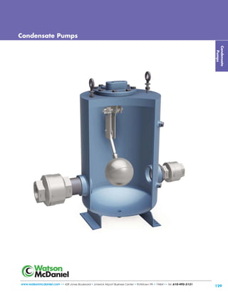
- 1. 129 www.watsonmcdaniel.com •• 428 Jones Boulevard • Limerick Airport Business Center • Pottstown PA • 19464 •• Tel: 610-495-5131 Condensate Pumps Condensate Pumps
- 2. 130 Condensate Return Pumps Introduction What is a Boiler Feed Pump? A facility will often have a separate area that contains various components required for the generation of steam, such as a boiler, condensate holding or deaerator (DA) tank, boiler feed pump, water treatment, etc. Regulated by the boiler control system, the boiler feed pump sends condensate from the holding tank back to the boiler. Condensate Pumps Condensate Return System Shown below is a simplified view of a steam system from steam generation to condensate return. Steam generated by the boiler travels through the steam distribution lines supplying steam to various pieces of process equipment. The steam flowing to this equipment is separated from the condensate return lines by steam traps. Relatively small steam traps, referred to as “Drip traps,” are used for optimization and protection of steam systems by draining condensate from steam distribution lines into the condensate return line. Process Applications refer to draining condensate from the actual process using the steam into the condensate return line. The steam traps used in these applications have relatively high condensate capacity and are referred to as “Process traps”. A large plant may have many separate pieces of process equipment and thousands of drip traps discharging condensate into the condensate return lines. On efficiently run steam systems, this condensate is returned back to the boiler for reuse. In certain cases, the steam pressure of the system may be sufficient to push the condensate through the steam traps and condensate return lines, back to the condensate holding tank in the boiler room. In most practical situations, however, one or more condensate return pumps are required to assist in overcoming gravity, pressure drops from long piping runs, and back pressures in return lines. Condensate Return Pumps are either electrically-driven centrifugal pumps or non-electric mechanical pumps that use steam pressure as the motive force to pump the condensate. Non-electric pumps are referred to as Pressure Motive Pumps (PMPs). What are Condensate Return Pumps & when are they required? Roof Vented Receiver Pump Steam Jacketed Kettle Vat Process Process Steam Trap Process Steam Trap Drip Trap TD600S Drip Trap TD600S Steam Distribution & Condensate Return System Steam travels through piping Process 1 Process 2 Condensate Return Pump Boiler Feed Water Boiler Feed Pump Steam Flash Steam Vent www.watsonmcdaniel.com •• Pottstown PA • USA • Tel: 610-495-5131 Condensate Return Line
- 3. Electric Pumps Electric Condensate Return Pumps are designed to work intermittently, discharging condensate only when the receiver tank is nearly full. This is accomplished with a float switch. A float connected to the switch assembly rises when condensate enters the tank. Once it rises above a set point, the switch energizes the motor on the pump, which runs until the water level drops below the bottom position of the float switch. The switch then de-energizes the motor to shut off the pump. Watson McDaniel electric pumps are offered in Simplex and Duplex models. 131 Condensate Pumps What is the purpose of a Vented Receiver? Condensate from several different sources, at different pressures, are often discharging into the same return line. The discharge from one of the higher pressure sources could easily increase the pressure in the return line, which would stop the discharge from a critical process application operating at lower pressures. By connecting the condensate return line to a vented receiver, the pressure in the return line will be effectively equalized to atmospheric pressure, allowing condensate to freely drain from all condensate sources. This is an extremely important and often overlooked aspect of any properly operating steam and condensate return system. The receiver and vent must be adequately sized to allow for the discharge of flash steam without building up excessive pressure. Higher condensate pressures or loads would require larger receiver and vent sizes. Condensate then flows by gravity from the vented receiver to the condensate return pump and is then returned back to the boiler room. Condensate Return Pumps Introduction Mechanical stand-alone Pressure Motive Pumps (PMPs) A stand-alone Pressure Motive Pump (PMP) consists of a pump tank with internal operating mechanism, and a set of inlet and outlet check valves. Pump tanks can be made from ductile iron (PMPC), fabricated steel (PMPF) or stainless steel (PMPSS). A PMP requires some form of a separate vented receiver tank that collects the condensate prior to entering the pump. This vented receiver is required to neutralize the pressure in the condensate return line by venting the flash steam to the atmosphere. Pumps with Receiver Tanks (Standard Skid Systems) Simplex, Duplex, and Triplex packaged systems include stand alone pumps and check valves with a vented receiver tank, mounted on a steel base and frame. Multiple pumping units can be used for increased capacity or for system redundancy. The stand-alone pumps are available in ductile iron, carbon steel and stainless steel; options include sight glasses, insulation jackets, cycle counters, motive and vent piping, pressure regulators, steam traps, strainers and ASME code stamp. All components of the system are properly sized and pre-piped together; requiring only four connections to be made in the field. Mechanical & Electric Condensate Return Pumps Tel: 610-495-5131 • Pottstown PA • USA •• www.watsonmcdaniel.com Vented Receiver PMPs PMP (stand-alone pump) Pressure Motive Pumps (PMPs) are non-electric pumps which return condensate back to the boiler room; using steam pressure as the motive force. PMPs can be supplied as stand-alone units – which include a pump tank, the internal operating mechanism, and a set of inlet and outlet check valves, or: as a packaged system – which also includes the vented receiver tank (to collect the condensate) mounted on a common base. What are Pressure Motive Pumps (PMPs)? Pump Tank Internal Mechanism Check Valve
- 4. Installation of mechanical type PMP’s vs. Electric pumps: Standard Electric Pumps are supplied with a receiver tank and are intended for lower pressure steam systems. In these instances, the vent size on the receiver tank should be adequate to vent minimal flash steam, allowing condensate to freely enter the receiver and to adequately cool prior to being pumped. In higher pressure steam systems, the condensate temperature is hotter, resulting in more flash steam as the condensate is discharged through steam traps and into the return line. Additional options may be required for the electric pumps if condensate does not cool to suitable temperatures. PMPs discharge high temperature condensate that drains from vented receivers. A stand-alone PMP pump tank cannot be used as the vented receiver since it is intermittently pressurized with steam or air to pump the condensate. PMPs require a separate vented receiver to collect the condensate and to vent the flash steam to atmosphere. The Simplex, Duplex or Triplex packaged systems include the separate vented receiver tank mounted on a common base along with the PMP(s). Vented Receivers should generally be sized to maintain 0 psig in both the receiver and condensate return line upstream of the receiver. This helps ensure free drainage of condensate from sources that may be operating at both high and low pressure. Sizing criteria is based on condensate pressure and the amount of the flash steam created. Undersizing the receiver or the vent will increase the pressure in the receiver and condensate return line, possibly causing issues with condensate drainage from process equipment upstream. Undersizing of the vent will increase the velocity of flash steam in the pipe which could possibly draw condensate from the receiver and discharge it out of the vent. 132 Why choose a PMP instead of an electric (centrifugal) condensate return pump? Reliability is the primary purpose for selecting Mechanical type PMP’s instead of Electric condensate pumps. Electric pumps require a mechanical seal to prevent the leakage of liquid around the rotating shaft that drives the impeller. The liquid being pumped acts as a lubricant so the seal faces of the mechanical seal may rotate freely against each other. When the liquid remains relatively cool, the mechanical seal could last for many years. However, hot condensate can flash to steam between the seal faces leading to seal failure. A centrifugal pump creates a low pressure zone at the eye of the impeller which draws the fluid into the pump. Hot condensate can flash into steam in the low pressure zone causing Cavitation. Cavitation happens when bubbles form in the liquid on the inlet side of the pump that will re-compress on the outlet side, causing erosion of the impeller and pump housing. When a pump cavitates, it often sounds like marbles or sand is being pumped. This flashing also blocks the flow of incoming condensate; causing the pump to run dry which decreases performance and also leads to seal failure. 1) PMP’s do not have any seals to fail. 2) No cavitation can occur because the body of the pump is filled by the natural flow due to gravity from a vented receiver, and then discharged by steam pressure. Therefore, Pressure Motive pumps are much more forgiving than centrifugal pumps when pumping hot condensate. flash steam condensate condensate return line motive steam vent to atmosphere steam inlet pump exhaustfilling head inlet check valve outlet check valve Condensate from Multiple Sources roof Condensate Return Pumps Introduction • Applications for using PMPs Condensate Condensate Pumps Vented Receiver Pressure Motive Pump Pump (PMP) with a Vented Receiver A Vented Receiver (or Flash Tank) is used to collect the condensate generated from one or several different sources (drip & process applications) in the facility. Pressure from the Flash steam generated by the hot condensate is vented to the atmosphere to maintain atmospheric pressure (0 PSIG) in the receiver tank. This assures that condensate will freely flow by gravity to the receiver tank and then to the pump tank, avoiding potential condensate back-up. www.watsonmcdaniel.com •• Pottstown PA • USA • Tel: 610-495-5131 0 PSIG
- 5. 133 Condensate Pumps Condensate Return Pumps Introduction • Applications for using PMPs outlet openclosed inlet FLOW 1 Condensate flows from the receiver tank through the inlet check valve and fills the pump tank. During the filling cycle the float inside the tank rises. 2 When the pump tank has filled to the trip point, the mechanism triggers, opening the motive gas inlet valve and simultaneously closing the vent valve. This allows motive pressure to enter the pump body, which drives the condensate thru the outlet check valve into the condensate return line. During the discharge cycle, the liquid level and the float inside the pump tank drop. 3 At the lower trip point, the mechanism triggers and the motive gas inlet valve to the pump tank closes and simultaneously the vent valve opens. The fill and discharge cycle then repeats. outlet closedopen inlet MOTIVE INLET (closed) VENT OUTLET (open) outlet closedopen inlet Open Closed FLOW FLOW Operation of PMP Pressure Motive Pump The positions of the Vent and Motive valves control the filling and discharge of the pump. The Vent valve must be open during the filling cycle to allow air or steam in the pump tank to be displaced as water enters the pump. Since water flows into the pump tank by force of gravity, the pump tank pressure must be neutralized for the pump tank to fill. When the pump tank reaches its fill point the vent valve closes and the motive valve opens. The incoming steam pressure rapidly forces the water out of the pump tank through the outlet check valve. When the pump tank empties, the vent valve opens and motive inlet valve closes. Vent Outlet: Open position, allowing any pressure in the pump tank to vent out and water to freely enter pump by gravity. Motive Inlet: Closed position Condensate level rising Condensate level falling Vent Outlet: Closed Motive Inlet: Open; steam pressure enters tank and discharges condensate Condensate level rising Vent Outlet: Open position, allowing any pressure in the pump tank to vent out and water to freely enter pump by gravity. Motive Inlet: Closed Position MOTIVE INLET (open) VENT OUTLET (closed) Closed Open Check Valves The inlet check valve on the PMP system must have a very low cracking pressure (opening pressure) so that the liquid will freely enter the pump tank. The proper check valve is very critical to the proper operation of the PMP system. Watson McDaniel recommends using spring-loaded stainless steel check valves with ¼ PSI cracking pressure. Tel: 610-495-5131 • Pottstown PA • USA •• www.watsonmcdaniel.com Pump Filling Pump Discharging Pump Filling
- 7. 135 Condensate Return Pumps Introduction • Pressure Motive Pump Components Condensate Pumps Check Valves The inlet check valve on the PMP system must have a very low cracking pressure (opening pressure) so that the liquid will freely enter the pump tank. The proper check valve is very critical to the proper operation of the PMP system. Watson McDaniel recommends using spring-loaded stainless steel check valves with ¼ PSI cracking pressure. Snap-Assure Pump Mechanism 1) Cover & mechanism bolt to top of pump tank. 2) Mechanism is field-repairable by replacing any of the functioning components such as springs and valve seats. 3) Mechanism can fit other manufacturers’ pump tanks. Pump Tank Made in various materials & styles: Ductile Iron, Fabricated Steel, Stainless Steel Check Valve Check Valve Motive Steam Inlet & Vent Valves Threaded into mechanism cover. Outlet Inlet Pump Mechanism Tel: 610-495-5131 • Pottstown PA • USA •• www.watsonmcdaniel.com Cover
- 8. 136 Mechanical Condensate Return Pumps are available as: 1) PMP (Pressure Motive Pump - Stand-Alone Unit) or 2) Pump System (Pumps with Vented Receiver Tanks): Mechanical PMP Stand-Alone Pumps Watson McDaniel’s Pressure Motive Pump (PMP stand-alone unit) consists of the pump tank, which is made from ductile iron, fabricated steel, or stainless steel, and Watson McDaniel’s patented “Snap-Assure” internal operating mechanism, along with a set of inlet and outlet check valves. An additional vented receiver or flash tank is required to collect the condensate before it enters the pump. Watson McDaniel offers a full line of PMP accessories, including custom tanks, insulation jackets, gauge glasses, cycle counters, pre-piped accessories, pump mechanisms, check valves and anything else you may need to maintain your system. Stand-Alone Units - Pressure Motive Pumps PMPC Cast Ductile Iron PMPF Fabricated Carbon Steel PMPLS Fabricated Carbon Steel (Reduced-Profile) Ductile Iron Pump Tanks Ductile Iron is far superior to cast iron in handling higher pressures and temperatures. Ductile iron is also extremely corrosion resistant to condensate and water and can last in excess of 50 years before tank replacement is required. Our ductile iron tanks can be ASME coded on request. Fabricated Carbon Steel Pump Tanks Carbon steel tanks are required in certain industrial facilities such as chemical and petrochemical refineries. However, fabricated cast steel is much less corrosion-resistant to condensate than ductile iron. Our carbon steel tanks are standard ASME coded. Fabricated Stainless Steel Pump Tanks Stainless steel (304L) tanks are extremely corrosion-resistant, giving increased longevity and can serve as a substitute for fabricated carbon steel tanks. Low Profile Pump Tanks Low-profile tanks are required when vertical space for adequate filling head of the pump is limited. Significantly more corrosion-resistant to condensate when compared to carbon steel. Carbon Steel may be required by code in Chemical and Petro-Chemical industries (required in certain industries). Several choices of pump body materials, types and configurations are available to meet specific customer applications: Condensate Return Pumps Introduction Condensate Pumps PMPSP Sump Drainer (non-electric sump pump) Sump drainers are used to pump water from pits or sumps using steam or air pressure. They are similar to the standard PMP models except that they discharge vertically upwards. This piping configuration allows them to be lowered into a sump or pit. Can serve as a substitute for fabricated carbon steel tanks for extended life or when Stainless Steel is required. For applications requiring large transfer rates of condensate or other liquids. PMPSS 304L Stainless Steel (Corrosion Resistant) PMPBP Carbon Steel (High-Capacity) PMPNT Ductile Iron or Stainless Steel (Low-Profile) For lower capacity applications. www.watsonmcdaniel.com •• Pottstown PA • USA • Tel: 610-495-5131 Lower in height than PMPF. Required when vertical space for adequate filling head of the pump is limited.
- 9. 137 Pump Systems (Pumps with Receiver Tanks) The PMPC, PMPF & PMPLS pump units are also available with a Vented Receiver mounted on a common base. The vented receiver is needed to collect the condensate which then drains by gravity into the pump tank. These standard Simplex, Duplex and Triplex packaged systems include stand-alone pump(s) and check valves with a vented receiver tank mounted on a steel base and frame. Multiple pumping units can be used for increased capacity or for system redundancy. The pump units are available in ductile iron (PMPC) or carbon steel (PMPF). Additional options include sight glasses, insulation jackets, cycle counters, motive and vent piping, pressure regulators, steam traps, strainers, ASME code stamps, etc. Condensate Return Pumps Introduction Condensate Pumps Duplex Pumping System (shown) More than one pump can be used for increased capacity or system redundancy. Vented Receiver Tank Check Valves Receiver Vent Adequately sized vent is important to neutralize pressure that is generated by flashing condensate. This allows condensate to freely flow by gravity into the receiver tank and then to pump tank. System mounted on steel base & frame Pump Tanks High pressure steam enters through Steam Inlet Valve and is used to pump condensate. Condensate drains by gravity from receiver tank into pump tanks Inlet Check Valves (2)Outlet (Discharge) Simplex Pumping System (shown) Single pump with receiver tank mounted on a common base. Pump Tank Vented Receiver Tank Outlet (Discharge) Check Valve Inlet Check Valve Receiver Vent System mounted on steel base & frame Tel: 610-495-5131 • Pottstown PA • USA •• www.watsonmcdaniel.com
- 10. 138 PMPC Typical Applications The PMPC model Ductile Iron non-electric pressure motive pump is typically used when liquids must be moved to higher elevation, higher pressure or extended distances. This stand-alone pump is capable of operating with a maximum motive pressure of 200 PSIG provided by steam, air or other gas supply. ASME “UM” code stamp is available. Features • Equipped with our Patented “Snap-Assure” Mechanism which extends the useful life of the pump • Mechanism incorporates heat-treated stainless steel wear items • All stainless steel internals for ultimate corrosion resistance • Dual compression springs made from Inconel-X-750 for high-temperature corrosive service • Operates using steam, air, nitrogen or other pressurized gases as the motive force • Non-Electric – can be used in remote locations or NEMA 4, 7, 9 and hazardous areas Sample Specification The non-electric pressure powered pump shall be capable of operating with a maximum motive pressure of 200 PSIG provided by steam, air or other gas supply. The pump body shall be cast ASTM A-395 Ductile Iron capable of an ASME “UM” code stamp if requested. The pump mechanism shall be float operated with a patented “Snap-Assure” feature constructed of all stainless steel materials with all load bearing points hardened for extended service life. The mechanism shall feature two Inconel springs used in compression with motive & vent valves hardened to 40c Rockwell. Model PMPC Body Ductile Iron Cover Ductile Iron Check Valves Stainless Steel PMO Max. Operating Pressure 200 PSIG TMO Max. Operating Temperature 388ºF PMA Max. Allowable Pressure 200 PSIG @ 650˚F TMA Max. Allowable Temperature 650ºF @ 200 PSIG MATERIALS Body & Cover Ductile Iron Cover Gasket Grafoil Cover Bolts Steel Inlet Valve Hardened Stainless Steel 40 Rc Vent Valve Hardened Stainless Steel 40 Rc Mechanism Yoke 304 Stainless Steel Ball Float 304 Stainless Steel Check Valves Stainless Steel Springs Inconel-X-750 Other Internal Components Stainless Steel DIMENSIONS – inches Size Weight (Inlet x Outlet) Model Code A B C (lbs) 1” x 1” PMPC-1X1-N-SS 291/2 6 6 360 11/2” x 1” PMPC-1.5X1-N-SS 303/4 71/2 6 365 11/2” x 11/2” PMPC-1.5X1.5-N-SS 311/4 71/2 71/2 367 2” x 1” PMPC-2X1-N-SS 31 8 6 370 2” x 11/2” PMPC-2X1.5-N-SS 321/2 8 71/2 380 2” x 2” PMPC-2X2-N-SS 323/4 8 8 385 3” x 2” PMPC-3X2-N-SS 351/4 91/4 8 390 Snap-Assure U.S. Patent No. 6572340 Stand-Alone Pumps CAST DUCTILE IRON TANK Pressure Motive Pump 1”NPT Vent B 1/2”NPT Motive Optional Gauge Glass 24.75” 4.20” 1.19” C A Lifting Eyes OUTLETINLET OUTLETINLET 1.19” Condensate Pumps Check Valve Check Valve The PMPC Stand Alone Pump consists of pump tank, internal mechanism, and inlet and outlet stainless steel check valves. www.watsonmcdaniel.com •• Pottstown PA • USA • Tel: 610-495-5131
- 11. Typical Applications The PMPF model Carbon Steel non-electric pressure motive pump is typically used when liquids must be moved to higher elevation, higher pressure or extended distances. This stand-alone pump is capable of operating with a maximum motive pressure of 200 PSIG provided by steam, air or other gas supply. These tanks are fabricated with 1/8” corrosion allowance and receive the ASME “UM” code stamp. Features • Equipped with our Patented “Snap-Assure” Mechanism which extends the useful life of the pump • Mechanism incorporates heat-treated stainless steel wear items • All stainless steel internals for ultimate corrosion resistance • Dual compression springs made from Inconel-X-750 for high-temperature corrosive service • Operates using steam, air, nitrogen or other pressurized gases as the motive force • Non-Electric – can be used in remote locations or NEMA 4, 7, 9 and hazardous areas Sample Specification The non-electric pressure powered pump shall be capable of operating with a maximum motive pressure of 200 PSIG provided by steam, air or other gas supply. The pump body shall be fabricated carbon steel and certified with the ASME “UM” code stamp. The pump mechanism shall be float operated with a patented “Snap-Assure” feature constructed of all stainless steel materials with all load bearing points hardened for extended service life. The mechanism shall feature two Inconel springs used in compression with motive & vent valves hardened to 40c Rockwell. 139 Model PMPF Body Carbon Steel Cover Carbon Steel Check Valves Stainless Steel PMO Max. Operating Pressure 200 PSIG TMO Max. Operating Temperature 388ºF PMA Max. Allowable Pressure 250 PSIG @ 650˚F MATERIALS Body & Cover Carbon Steel Cover Gasket Grafoil Cover Bolts Steel Inlet Valve Hardened Stainless Steel 40 Rc Vent Valve Hardened Stainless Steel 40 Rc Mechanism Yoke 304 Stainless Steel Ball Float 304 Stainless Steel Check Valves Stainless Steel Springs Inconel-X-750 Other Internal Components Stainless Steel PMPF DIMENSIONS – inches Size Weight (Inlet x Outlet) Model Code A B C (lbs) 1” x 1” PMPF-1X1-N-SS 301/2 6 6 215 11/2” x 1” PMPF-1.5X1-N-SS 313/4 71/2 71/2 220 11/2” x 11/2” PMPF-1.5X1.5-N-SS 321/4 71/2 6 223 2” x 1” PMPF-2X1-N-SS 32 8 6 225 2” x 11/2” PMPF-2X1.5-N-SS 331/2 8 71/2 230 2” x 2” PMPF-2X2-N-SS 333/4 8 8 235 3” x 2” PMPF-3X2-N-SS 351/4 91/4 8 240 Condensate Pumps FABRICATED STEEL TANK Pressure Motive Pump Stand-Alone Pumps 1”NPT Vent B 1/2”NPT Motive 29.31” 9.31” 1.19” C A Lifting Eyes 1.19” Snap-Assure U.S. Patent No. 6572340 Drain OUTLETINLET Check Valve Check Valve The PMPF Stand Alone Pump consists of pump tank, internal mechanism, and inlet and outlet stainless steel check valves. Tel: 610-495-5131 • Pottstown PA • USA •• www.watsonmcdaniel.com Optional Gauge Glass
- 12. 140 Typical Applications The PMPSS model Stainless Steel non-electric pressure motive pump can be used in harsh and corrosive environments or as a substitute for fabricated carbon steel tanks for increased longevity. This stand-alone pump is capable of operating with a maximum motive pressure of 150 PSIG provided by steam, air or other gas supply. These pumps receive the ASME “UM” code stamp. Features • Equipped with our Patented “Snap-Assure” Mechanism which extends the useful life of the pump • Mechanism incorporates heat-treated stainless steel wear items • All stainless steel internals for ultimate corrosion resistance • Dual compression springs made from Inconel-X-750 for high-temperature corrosive service • Operates using steam, air, nitrogen or other pressurized gases as the motive force • Non-Electric – can be used in remote locations or NEMA 4, 7, 9 and hazardous areas Sample Specification The non-electric pressure powered pump shall be capable of operating with a maximum motive pressure of 150 PSIG provided by steam, air or other gas supply. The pump body shall be 304L Stainless Steel and certified with the ASME “UM” code stamp. The pump mechanism shall be float operated with a patented “Snap-Assure” feature constructed of all stainless steel materials with all load bearing points hardened for extended service life. The mechanism shall feature two Inconel springs used in compression with motive and vent valves hardened to 40c Rockwell. Model PMPSS Body 304L Stainless Steel * Cover 304L Stainless Steel * Check Valves Stainless Steel PMO Max. Operating Pressure 150 PSIG TMO Max. Operating Temperature 366 ºF PMA Max. Allowable Pressure 150 PSIG @ 650˚F MATERIALS Body & Cover 304L Stainless Steel Cover Gasket Grafoil Cover Bolts Steel Inlet Valve Hardened Stainless Steel 40 Rc Vent Valve Hardened Stainless Steel 40 Rc Mechanism Yoke 304 Stainless Steel Ball Float 304 Stainless Steel Check Valves Stainless Steel Springs Inconel-X-750 Other Internal Components Stainless Steel DIMENSIONS – inches Size Weight (Inlet x Outlet) Model Code A B C (lbs) 1” x 1” PMPSS-1X1-N-SS 301/2 6 6 215 11/2” x 1” PMPSS-1.5X1-N-SS 313/4 71/2 71/2 220 11/2” x 11/2” PMPSS-1.5X1.5-N-SS 321/4 71/2 6 223 2” x 1” PMPSS-2X1-N-SS 32 8 6 225 2” x 11/2” PMPSS-2X1.5-N-SS 331/2 8 71/2 230 2” x 2” PMPSS-2X2-N-SS 333/4 8 8 235 3” x 2” PMPSS-3X2-N-SS 351/4 91/4 8 240 * For special 316L SS, consult factory. PMPSSStand-Alone Pumps STAINLESS STEEL TANK Pressure Motive Pump 1”NPT Vent B 1.19” 1/2”NPT Motive 29.31” 9.31” 1.19” C A Lifting Eyes Condensate Pumps Snap-Assure U.S. Patent No. 6572340 Drain OUTLETINLET Check Valve Check Valve The PMPSS Stand Alone Pump consists of pump tank, internal mechanism, and inlet and outlet stainless steel check valves. www.watsonmcdaniel.com •• Pottstown PA • USA • Tel: 610-495-5131 Optional Gauge Glass
- 13. 141 Typical Applications The PMPLS model Carbon Steel non-electric pressure motive pump is a lower profile than the standard PMPF model. It is sometimes required when draining condensate from process equipment that is positioned close to the ground, which limits the filling head of the pump. This stand-alone pump is capable of operating with a maximum motive pressure of 150 PSIG provided by steam, air or other gas supply. These pumps receive the ASME “UM” code stamp. Features • Equipped with our Patented “Snap-Assure” Mechanism which extends the useful life of the pump • Mechanism incorporates heat-treated stainless steel wear items • All stainless steel internals for ultimate corrosion resistance • Dual compression springs made from Inconel-X-750 for high-temperature corrosive service • Operates using steam, air, nitrogen or other pressurized gases as the motive force • Non-Electric – can be used in remote locations or NEMA 4, 7, 9 and hazardous areas Sample Specification The non-electric pressure powered pump shall be capable of operating with a maximum motive pressure of 150 PSIG provided by steam, air or other gas supply. The pump body shall be fabricated carbon steel and certified with the ASME “UM” code stamp. The pump mechanism shall be float operated with a patented “Snap-Assure” feature constructed of all stainless steel materials with all load bearing points hardened for extended service life. The mechanism shall feature two Inconel springs used in compression with motive and vent valves hardened to 40c Rockwell. Model PMPLS Body Carbon Steel Cover Carbon Steel Check Valves Stainless Steel PMO Max. Operating Pressure 150 PSIG TMO Max. Operating Temperature 366ºF PMA Max. Allowable Pressure 150 PSIG @ 650˚F MATERIALS Body & Cover Carbon Steel Cover Gasket Grafoil Cover Bolts Steel Inlet Valve Hardened Stainless Steel 40 Rc Vent Valve Hardened Stainless Steel 40 Rc Mechanism Yoke 304 Stainless Steel Ball Float 304 Stainless Steel Check Valves Stainless Steel Springs Inconel-X-750 Other Internal Components Stainless Steel DIMENSIONS – inches Size Weight (Inlet x Outlet) Model Code A B C (lbs) 1” x 1” PMPLS-1X1-N-SS 291/2 55/8 55/8 200 11/2” x 1” PMPLS-1.5X1-N-SS 303/4 7 55/8 205 11/2” x 11/2” PMPLS-1.5X1.5-N-SS 321/8 7 7 210 Note: Optional 200 PSIG PMA/PMO. Consult Factory. Condensate Pumps PMPLS CARBON STEEL LOW-PROFILE TANK Pressure Motive Pump Stand-Alone Pumps 1”NPT Vent 1.19” 23.75” 1/2”NPT Motive 2.75” 1.19” 1/2”FNPT Drain Lifting Eyes B C A Snap-Assure U.S. Patent No. 6572340 OUTLETINLET Check Valve Check Valve The PMPLS Stand Alone Pump consists of pump tank, internal mechanism, and inlet and outlet stainless steel check valves. Tel: 610-495-5131 • Pottstown PA • USA •• www.watsonmcdaniel.com 141 Optional Gauge Glass
- 14. Typical Applications The PMPNT(S) non-electric pressure motive pumps are light in weight and have an extremely low-profile. This stand-alone pump is capable of operating with a maximum motive pressure of 125 PSIG provided by steam, air or other gas supply. ASME Code Stamp available upon request. Features • Equipped with our proven, Patented “Snap-Assure” mechanism which extends the useful life of the pump • Internal mechanism can be removed from the top of the pump while pump remains piped in line • Mechanism incorporates heat-treated stainless steel wear items for ultimate corrosion resistance • Dual compression springs made from Inconel-X-750 for high-temperature, corrosive service • Non-Electric – can be used in remote locations or NEMA 4, 7, 9 and hazardous areas • Operates using steam, air, nitrogen or other pressurized gas as the motive force Inlet Check Valve 1/2”NPT Motive Inlet 1/2”NPT Vent Outlet Check Valve 1.19” 12.00” dia. 2.00” 13.19” 11.94” 25.21” 2.06” 1/2”NPT Drain FLOW OUTLETINLET Check Valve Check Valve 142 CAPACITIES – Condensate (lbs/hr) Motive Back 6” Filling Head Pressure Pressure Steam Motive Steam Motive (PSIG) (PSIG) 1” x 1” 11/2” x 11/2” 5 2 1225 2131 10 5 1204 2093 10 2 1391 2419 25 15 1171 2037 25 5 1458 2535 50 40 987 1716 50 10 1491 2593 75 60 992 1726 75 40 1262 2195 75 15 1505 2617 100 80 995 1731 100 60 1209 2102 100 15 1545 2687 125 100 997 1734 125 80 1174 2042 125 60 1316 2288 125 15 1570 2731 PMPNTStand-Alone Pumps DUCTILE IRON MINI-PUMP Pressure Motive Pump Model PMPNT PMPNTS Body Ductile Iron Stainless Steel Cover Stainless Steel Stainless Steel Sizes 1”, 11/2” NPT 11/2” FLG or NPT Check Valves Stainless Steel Stainless Steel PMO Max. Operating Pressure 125 PSIG 125 PSIG TMO Max. Operating Temperature 366ºF 366ºF PMA Max. Allowable Pressure 150 PSIG @ 450˚F 150 PSIG @ 450˚F MATERIALS Body PMPNT Ductile Iron SA-395 Body PMPNTS Stainless Steel CF3M Cover Stainless Steel CF8 Cover Gasket Garlock Cover Bolts Steel Inlet Valve Hardened Stainless Steel 40 Rc Vent Valve Hardened Stainless Steel 40 Rc Ball Float 300 Stainless Steel Check Valves Stainless Steel 316SS CF3 Springs Inconel-X-750 Other Internal Components Stainless Steel Condensate Pumps Note: Multiply Capacity by 1.16 for 12” Fill Head. Multiply Capacity by 1.28 for 18” Fill Head. The PMPNT Stand Alone Pump consists of pump tank, internal mechanism, and inlet and outlet stainless steel check valves. PMO Weight Size Model Code PSI lbs Ductile Iron Pump Body (NPT) 1” x 1” PMPNT-1X1-N-SS 125 85 11/2” x 11/2” PMPNT-1.5X1.5-N-SS 125 95 Stainless Steel Pump Body (NPT or 150# FLG) 11/2” x 11/2” PMPNTS-1.5X1.5-N-SS 125 95 11/2” x 11/2” PMPNTS-1.5X1.5-F150-SS 125 98 www.watsonmcdaniel.com •• Pottstown PA • USA • Tel: 610-495-5131
- 15. 143 Typical Applications The PMPBP model non-electric Carbon Steel pressure motive pump is extremely high-capacity for applications requiring large transfer of condensate or other liquids. This stand-alone pump is capable of operating with a maximum motive pressure of 150 PSIG provided by steam, air, nitrogen or other pressurized gases as the motive force. ASME “U” Code Stamp available upon request. Features • All stainless steel internals for ultimate corrosion resistance • Operates using steam, air, nitrogen or other pressurized gas as the motive force • Non-Electric – can be used in remote locations or NEMA 4, 7, 9 and hazardous areas Options • Cycle counter for measuring the amount of condensate flow through the pump. • Insulation jackets are available to stop heat losses through the pump body. • Sight glass for monitoring liquid level inside pump body. Model PMPBP Body Carbon Steel Cover Carbon Steel Check Valves Stainless Steel & Steel PMO Max. Operating Pressure 150 PSIG TMO Max. Operating Temperature 366ºF PMA Max. Allowable Pressure 150 PSIG @ 470˚F Condensate Pumps PMPBP CARBON STEEL HIGH-CAPACITY TANK Pressure Motive Pump Stand-Alone Pumps 3/4”FNPT Gauge Glass Conn. 17.50” 2”FNPT Motive 3/4”NPT Drain 2.75” 5.12” 2”FNPT Vent 1.25” 46.56” 8.75” 37.12” 66.69” face-to- face 36” dia. 8.75” 24” 12” 11/16”dia. holes 4 Pls 4”150# Socket Weld RF Flange 16.50” 4”150# RF Flange FLOW 8.75” The PMPBP Stand Alone Pump consists of pump tank, internal mechanism, and inlet and outlet check valves. Size PMO Weight (Inlet x Outlet) Connection Model Code PSI (lbs) 4” x 4” 150#FLG PMPBP-4X4-F150-SS 150 1050 MATERIALS Body & Cover Carbon Steel Cover Gasket Non-Asbestos Cover Bolts Steel Inlet Valve Stainless Steel Vent Valve Stainless Steel Mechanism Yoke 304 Stainless Steel Ball Float 304 Stainless Steel Check Valves Stainless Steel & Steel Springs Stainless Steel Other Internal Components Stainless Steel Tel: 610-495-5131 • Pottstown PA • USA •• www.watsonmcdaniel.com
- 16. 144 Typical Applications The PMPSP Sump Drainer uses the same internal mechanism as the standard PMP models. The piping configuration is such that the liquid is discharged vertically out the top as opposed to horizontally out the side. This allows the unit to be easily positioned inside of a sump area. Condensate or water from the sump enters the tank through a stainless steel low resistance check valve. This unit is capable of operating with a maximum motive pressure of 150 PSIG using steam, air, nitrogen or other pressurized gas as the motive force. Features • Equipped with our Patented “Snap-Assure” Mechanism which extends the useful life of the pump • Mechanism incorporates heat-treated stainless steel wear items for ultimate corrosion resistance • Dual compression springs made from Inconel-X-750 for high-temperature corrosive service • Operates using steam, air, nitrogen or other pressurized gas as the motive force • Non-Electric – can be used in remote locations or NEMA 4, 7, 9 and hazardous areas • Built-in Strainer screen Model PMPSP/PMPSPL Body Carbon Steel Cover Ductile Iron Check Valves Stainless Steel PMO Max. Operating Pressure 150 PSIG TMO Max. Operating Temperature 366ºF PMA Max. Allowable Pressure 150 PSIG @ 650˚F Stainless Steel Check Valve OUTLET Stainless Steel Check Valve PMPSPSump Drainer The “PIT BOSS” Sump Drainer 2.56” 1”NPT Vent 1/2”NPT Motive 1.19” 5.00” 16.0” ø 1.19” 25.31” Condensate Pumps Snap-Assure U.S. Patent No. 6572340 PMPSPLPMPSP 30” www.watsonmcdaniel.com •• Pottstown PA • USA • Tel: 610-495-5131 21.41” 15.6” 1.10” 1/2”NPT Vent 1/2”NPT Motive 4.11” 1.19” 12.75” ø PMPSP PMPSPL OUTLET Stainless Steel Check Valve Stainless Steel Check Valve Water enters thru inlet protected by screen Screen Screen Water enters thru inlet protected by screen
- 17. 145 Discharge Line Disc Trap Inlet protected by Screen Minimum Diameter 18” PMPSP 14.75” PMPSPL Motive Steam or Air Water enters the inlet check valve thru a screened area at bottom of pump. After the pump fills, the internal mechanism is actuated and the pump is discharged by the motive steam or compressed air. Other compressed gases such as nitrogen can also be used. PMPSP Sump Drainer Vent Condensate Pumps PMPSPThe “PIT BOSS” Typical PMPSP Piping Configuration Sump Drainer Sump Drainer Size/Connection PMO Weight (Outlet) NPT Model Code PSI lbs 11/2” PMPSPL 150 110 11/2” PMPSP-1 150 230 2” PMPSP-2 150 270 2” PMPSP-3 150 290 Tel: 610-495-5131 • Pottstown PA • USA •• www.watsonmcdaniel.com PMPSP & PMPSPL PUMP CAPACITIES – Water (GPM) Motive Total Back PMPSPL PMPSP-1 PMPSP-2 PMPSP-3 Pressure Pressure (PSIG) (PSIG) 11/2” 11/2” 2” 2” 10 0 2.8 11.7 22.2 35 20 10 3.1 9.2 17.5 22 20 0 3.3 12.5 23.7 30 40 20 3.2 8.7 16.5 21 40 10 3.4 10.4 19.8 25 40 0 3.5 13.1 25 31.4 70 40 3.2 7.1 12.1 17 70 20 3.4 9.4 15 22.5 70 0 3.6 12.9 20.6 31 100 70 3.2 5.4 8.6 10.8 100 40 3.4 7.5 12 15 100 20 3.4 9.4 15 18.8 100 0 3.5 12.3 19.7 24.6 150 100 - 4.5 7.2 9 150 70 - 5.7 9.1 11.4 150 40 - 7.2 11.5 14.4 150 20 - 8.8 14 17.6 150 10 - 9.5 15.2 19 150 0 - 10.7 17.1 21.4
- 18. Gauge Glass 1/2”NPT 55.6” Auxillary Inlet 2”NPT Condensate Inlet 3”NPT Connects to Pump Exhaust 11/2” NPT 62.6”Condensate Outlet PMPC or PMPF Motive Steam Inlet 1/2”NPT Pump Exhaust 1” NPT 21 Gal. Receiver Drain 1”NPT 7.5” PMPC 12” PMPF 27.75” PMPC 32.00” PMPF Receiver Vent 4” 150# Flange 30.0” 40.0” 146 Standard Skid Mounted Systems SIMPLEX Systems PMPC & PMPFPump Systems Pumps with Receiver Tanks Pressure Motive Pumps Package Model Simplex, Duplex, Triplex Simplex, Duplex, Triplex Pump Model (PMP) PMPF PMPC Pump Body Material Carbon Steel Ductile Iron Receiver Material Carbon Steel Carbon Steel Check Valves 316 Stainless Steel 316 Stainless Steel PMO Max. Operating Pressure 200 PSIG 200 PSIG TMO Max. Operating Temperature 388ºF 388ºF PMA Max. Allowable Pressure 250 PSIG @ 650˚F 200 PSIG @ 650˚F Receiver Pressure Rating 150 PSIG @ 566˚F 150 PSIG @ 566˚F Connection NPT PMPC • Ductile Iron PMPF • Carbon Steel Receiver Inlet x Outlet Mode Code Mode Code Size Gallons Simplex Systems - One Pump with Receiver 1” x 1” S-PMPC-1X1-SS-21 S-PMPF-1X1-SS-21 21 11/2” x 1” S-PMPC-1.5X1-SS-21 S-PMPF-1.5X1-SS-21 21 2” x 1” S-PMPC-2X1-SS-21 S-PMPF-2X1-SS-21 21 2” x 11/2” S-PMPC-2X1.5-SS-21 S-PMPF-2X1.5-SS-21 21 2” x 2” S-PMPC-2X2-SS-21 S-PMPF-2X2-SS-21 21 3” x 2” S-PMPC-3X2-SS-21 S-PMPF-3X2-SS-21 21 Duplex Systems - Two Pumps with Receiver 3” x 2” D-PMPC-3X2-SS-48 D-PMPF-3X2-SS-48 48 3” x 2” D-PMPC-3X2-SS-75 D-PMPF-3X2-SS-75 75 3” x 2” D-PMPC-3X2-SS-116 D-PMPF-3X2-SS-116 116 Triplex Systems - Three Pumps with Receiver 3” x 2” T-PMPC-3X2-SS-75 T-PMPF-3X2-SS-75 75 3” x 2” T-PMPC-3X2-SS-116 T-PMPF-3X2-SS-116 116 Typical Applications Condensate Return Pressure Motive Pump (PMPs) with a Vented Receiver. Standardized Simplex, Duplex, Triplex, and Quadraplex packaged systems include stand-alone pump(s), check valves and vented receiver, mounted on a steel base and frame. Multiple pumping units can be used for increased capacity or for system redundancy. The PMP units are available in ductile iron, carbon steel and stainless steel. Additional options include sight glasses, insulation jackets, cycle counters, motive and vent piping, pressure regulators, steam traps, strainers, ASME code stamps, etc. Sample Specifications Unit shall be a Watson McDaniel, pre-packaged system to include pressure motive pump(s) with stainless steel check valves, an ASME vented receiver with “UM” code stamp, and interconnecting piping including inlet isolation valve. The carbon steel PMPF shall receive an ASME "UM" code stamp and the ductile iron PMPC shall offer it as an option. The pump mechanism shall be float operated with a patented “Snap-Assure” feature constructed of all stainless steel materials with all load bearing points hardened for extended service life, with no external seals or packing. Condensate Pumps www.watsonmcdaniel.com •• Pottstown PA • USA • Tel: 610-495-5131
- 19. 147 Vent 6” 150# Flange To Pump Exhaust 11/2” NPT Condensate Inlet 3”NPT Pump Exhaust 1” NPT Motive Steam Inlet 1/2”NPT Condensate Outlet 48 Gal. Receiver Auxillary Inlet 3”NPT Inspection Opening 2”NPT Gauge Glass 1/2”NPT 68.0” 59.0” 40.0” 44.0” TRIPLEX Systems Drain 1”NPT 27.75”PMPC 32.00”PMPF Gauge Glass 1/2”NPT 2”NPT 4”150# Flange Condensate Inlet 3”NPT 11/2” NPT Inspection Opening 2”NPT Connect to Pump Exhaust 11/2” NPT Pump Exhaust 1” NPT Motive Steam Inlet 1/2”NPT 75 Gal. Receiver Condensate Outlet 27.75”PMPC 32.00”PMPF 68.4” 59.0” Vent 6” 150# Flange PMPC or PMPF 64.0” 40.0” Receiver Standard Skid Mounted Systems PMPC & PMPF Pumps with Receiver Tanks Pressure Motive Pumps Pump Systems 7.5” PMPC 12” PMPF Drain 1”NPT 7.5” PMPC 12” PMPF Receiver PMPC or PMPF DUPLEX Systems Condensate Pumps Features • PMP pump systems reduce installation costs. Only 4 pipe connections are required in the field • Watson McDaniel ensures that vented receivers and other components are properly sized for optimum system performance • Watson McDaniel’s fully-qualified fabrication facility is ASME code certified. Our engineers can design and build complete custom systems to meet all your requirements Options • Gauge glass assembly • Cycle counter • Insulation covers • Motive steam drip trap • Overflow pipe connection • Pressure regulator for motive supply line ASME Certified Tel: 610-495-5131 • Pottstown PA • USA •• www.watsonmcdaniel.com
- 21. 149 Condensate Pumps PMP-Mechanical Condensate Return Pumps Capacity Charts Capacity Correction Factors for Alternate Filling Heads Pump Filling Head Inlet Size 6” 12” 18” 24” 36” 48” 60” 1” 1.00 1.10 1.20 1.30 1.50 11/2” 0.70 1.00 1.10 1.20 1.35 2” 0.70 1.00 1.10 1.20 1.35 3” 0.84 1.00 1.04 1.08 1.20 4” 0.80 1.00 1.10 1.15 1.20 NOTE: When the filling head differs from the standard filling height, the capacity of the pressure power pumps are either increased or decreased. For example, a pump with a 3” inlet that has a filling head of 36” as opposed to a standard filling head of 12”, will have a capacity increase of 20%. Multiply the value found in the Capacity Table above by 1.2. Capacity Correction Factors for Gas as Motive Pressure Pump % Back Pressure relative to Motive Pressure Inlet Size 10% 20% 30% 40% 50% 60% 70% 80% 90% 1” 1.00 1.13 1.16 1.20 1.25 1.30 1.35 1.40 1.45 11/2” 1.04 1.06 1.08 1.10 1.12 1.15 1.18 1.23 1.28 2” 1.04 1.06 1.08 1.10 1.12 1.15 1.18 1.23 1.28 3” 1.04 1.06 1.08 1.10 1.12 1.15 1.18 1.23 1.28 4” No Capacity Change Note: For low specific gravity applications, consult factory. CAPACITIES – Condensate (lbs/hr) Using steam as a motive pressure Motive Total Back PMPLS PMPC, PMPF, PMPSS* (12” Fill Head) PMPBP Pressure Pressure 6” Fill Head Duplex Triplex Quadraplex 4” x 4” (PSIG) (PSIG) 1” X 1” 11/2” X 1” 11/2” X 11/2” 2” X 1” 2” X 11/2” 2” X 2” 3” x 2” 3” x 2” 3” x 2” 3” x 2” 24” Head 5 2 1,760 1,860 1,920 2,860 3,180 3,540 5,000 10,000 15,000 20,000 16,600 10 5 1,870 2,200 2,450 4,350 4,840 5,380 7,210 14,420 21,630 28,840 19,000 10 2 2,200 3,030 3,370 6,880 7,650 8,500 11,110 22,220 33,330 44,440 22,600 25 15 1,650 3,130 3,480 4,990 5,550 6,170 8,230 16,460 24,690 32,920 33,200 25 10 1,980 3,600 3,990 6,560 7,290 8,100 10,780 21,560 32,340 43,120 40,300 25 5 2,300 4,700 5,200 7,970 8,860 9,850 13,350 26,700 40,050 53,400 46,200 50 40 1,650 2,280 2,530 3,370 3,750 4,170 5,670 11,340 17,010 22,680 33,300 50 25 1,980 4,050 4,500 6,800 7,560 8,440 11,550 23,100 34,650 46,200 40,100 50 10 2,300 4,700 5,240 7,970 8,860 9,850 13,440 26,880 40,320 53,760 47,000 75 60 1,540 2,400 2,660 3,600 4,000 4,440 6,340 12,680 19,020 25,360 32,900 75 40 1,980 3,780 4,190 5,920 6,580 7,320 9,870 19,740 29,610 39,480 39,400 75 15 2,420 5,130 5,700 8,580 9,540 10,600 14,330 28,660 42,990 57,320 47,200 100 80 1,650 2,750 3,060 4,160 4,630 5,150 6,860 13,720 20,580 27,440 27,200 100 60 1,870 3,600 4,000 5,560 6,180 6,870 9,100 18,200 27,300 36,400 35,100 100 40 2,090 4,700 5,210 6,880 7,650 8,500 11,270 22,540 33,810 45,080 42,100 100 15 2,420 5,400 6,010 8,740 9,720 10,800 14,330 28,660 42,990 57,320 48,000 125 115 1,430 2,380 2,640 3,270 3,640 4,050 4,960 9,920 14,880 19,840 19,500 125 100 1,540 2,980 3,330 4,140 4,600 5,130 6,390 12,780 19,170 25,560 25,300 125 80 1,760 3,430 4,100 5,400 6,000 6,670 8,540 17,080 25,620 34,160 32,200 125 60 1,980 4,170 4,850 6,600 7,340 8,160 10,530 21,060 31,590 42,120 38,500 125 40 2,200 5,100 5,950 7,760 8,630 9,590 12,500 25,000 37,500 50,000 44,000 125 15 2,420 5,850 6,660 9,240 10,270 11,420 15,100 30,200 45,300 60,400 49,200 150 120 1,590 2,650 2,940 3,400 3,780 4,200 5,690 11,380 17,070 22,760 21,600 150 100 1,640 3,150 3,490 4,320 4,800 5,350 7,000 14,000 21,000 28,000 29,000 150 80 1,860 3,800 4,230 5,490 6,100 6,770 9,100 18,200 27,300 36,400 34,500 150 60 2,080 4,500 5,000 6,660 7,400 8,240 11,120 22,240 33,360 44,480 40,300 150 40 2,300 5,290 5,870 7,920 8,800 9,780 13,220 26,440 39,660 52,880 44,700 150 15 2,520 6,100 6,820 9,450 10,500 11,680 15,500 31,000 46,500 62,000 49,500 175 140 - 2,600 2,900 3,800 4,200 4,650 6,200 12,400 18,600 24,800 - 175 120 - 3,100 3,400 4,400 4,850 5,400 7,200 14,400 21,600 28,800 - 175 100 - 3,600 4,000 5,100 5,700 6,300 8,400 16,800 25,200 33,600 - 175 60 - 4,850 5,400 6,900 7,700 8,550 11,400 22.800 34.200 45,600 - 175 40 - 6,200 6,900 8,900 9,850 10,950 14,600 29,200 43,800 58,400 - 175 15 - 7,500 8,350 10,600 11,900 13,200 17,600 35,200 52,800 70,400 - 200 160 - 2,400 2,700 3,500 3,800 4,300 5,700 11,400 17,100 22,800 - 200 140 - 3,100 3,400 4,400 4,900 5,400 7,200 14,400 21,600 28,800 - 200 100 - 4,200 4,650 5,950 6,600 7,350 9,800 19,600 29,400 39,200 - 200 80 - 4,700 5,250 6,750 7,500 8,300 11,100 22,200 33,300 44,400 - 200 40 - 6,800 7,550 9,700 10,800 11,950 15,950 31,900 47,850 63,800 - 200 15 - 8,400 9,350 12,000 13,300 14,800 19,700 39,400 59,100 78,800 - * PMPSS is rated to only 150 PSIG. Note: For PMPNT capacity, refer to PMPNT specification page. Stand Alone Pumps & Systems Capacity based on 12”Fill Head except as noted Tel: 610-495-5131 • Pottstown PA • USA •• www.watsonmcdaniel.com
- 22. 150 Pump Size The models of a Pressure Motive Pump are designated by the size of the inlet and outlet check valves (for example, a 3” x 2” PMPC or PMPF has a 3” Inlet check valve and a 2” outlet check valve). The larger the check valves, the larger the pump capacity. STAND-ALONE PUMPS include pump tank, internal pumping mechanism, and check valves. PUMP(S) WITH RECEIVER TANKS includes stand-alone pump(s), and vented receiver tank mounted together on a frame. These are available in Simplex, Duplex, Triplex and Quadraplex systems. When sizing and selecting a Pressure Motive Pump, Four system conditions are required: (See Diagram on following page) 1 Condensate Load: If condensate from several sources of equipment is required to be pumped, sum up the maximum flow rate of condensate each could produce separately. Motive Pressure: Normally steam is used; however, other gases can be used to pump the condensate, including Air or Nitrogen. 4 Filling Head: The Filling Head is measured between the bottom of the receiver tank and the top of the pump tank. It has a significant effect on pump capacity. 5 System Back Pressure: Pressure in condensate return line that pump will be operating against, as determined by condensate return line pressure and vertical height condensate must be lifted. Sample System Conditions: Condensate Load 8,000 lbs/hr Motive Steam Pressure 100 PSIG Filling Head 12" System Back Pressure: 40 PSIG (To find the pressure required to lift condensate in PSIG, multiply Vertical lift in feet by 0.433) PMP-Mechanical Condensate Return Pumps Sizing & Selection How to specify when ordering: Example: 1) Model PMPC 2) Size of Pump(s) 2”x 2” 3) Stand-alone Pump or Pump with Receiver Tank Simplex or Duplex (Note: Size of Receiver Tank must be specified when ordering Pump with Receiver Tank) 4) Options Gauge glass 5) When ordering a Customized Skid System, please confirm and specify Receiver size. For PMP Selection: Consult PMP Sizing Capacity Chart using 100 PSIG inlet pressure and 40 PSIG back pressure. A 2" x 2" pump has a capacity of 8,500 lbs/hr and is an appropriate selection. Pump choices are models PMPC, PMPF and PMPSS. 1 2 3 4 1 3 2 4 Vented Receiver (Open-Loop System) Condensate Pumps www.watsonmcdaniel.com •• Pottstown PA • USA • Tel: 610-495-5131
- 23. 151 System Back Pressure Receiver & Vent Sizing The purpose of the vented receiver is to neutralize the pressure inside the condensate return line so condensate will properly drain from the processes and into the pump tank. An undersized vent will increase the velocity of flash steam in the vent pipe, potentially pulling condensate from the receiver tank out the vent. It may also increase pressure in the receiver and condensate return line upstream of the receiver, possibly causing issues with condensate drainage from the steam traps. The table below lists vent and corresponding receiver sizes based on the amount of flash steam. The amount of flash steam generated is determined by the condensate flow rate and condensate pressure entering the vented receiver. Determine the amount of condensate in lbs/hr flowing into the vented receiver. The percentage of condensate that will flash into steam is based on the initial condensate pressure and the pressure inside the vented receiver. Since we are trying to achieve 0 psig, reference the 0 psig flash tank pressure to determine % flash steam. Multiply the % flash by the total condensate load. Example: 10,000 lbs/hr of condensate is generated at an estimated steam pressure of 20 psig. The percent (%) flash steam is 4.9%. Quantity of flash steam = .049 x 10,000 = 490 lbs/hr. From the table, select a Vent and Receiver size which can handle 600 lbs/hr of flash steam. (4” vent with a 10” receiver diameter and 36” length.) VENTED RECEIVER SIZING (inches) Quantity of Vent Line Receiver Flash Steam (lbs/hr) Diameter Diameter Length 75 1” 4” 36” 150 2” 6” 36” 300 3” 8” 36” 600 4” 10” 36” 900 6” 12” 36” 1200 6” 16” 36” 2000 8” 20” 60” 3000 8” 24” 60” 4000 10” 26” 60” 5000 10” 28” 60” 6000 12” 30” 72” 7000 12” 32” 72” 8000 14” 36” 72” PERCENT (%) FLASH STEAM Produced when condensate is discharged to atmosphere or into a flash tank controlled at various pressures Condensate Flash Tank Pressure (PSIG) Pressure (PSIG) 0 5 10 20 30 40 60 80 100 5 1.6 0.0 10 2.9 1.3 0.0 15 3.9 2.4 1.1 20 4.9 3.3 2.1 0.0 30 6.5 5.0 3.7 1.7 0.0 40 7.8 6.3 5.1 3.0 1.4 0.0 60 10.0 8.5 7.3 5.3 3.7 2.3 0.0 80 11.8 10.3 9.1 7.1 5.5 4.2 1.9 0.0 100 13.3 11.8 10.6 8.7 7.1 5.8 3.5 1.6 0.0 125 14.9 13.5 12.3 10.4 8.8 7.5 5.3 3.4 1.8 150 16.3 14.9 13.7 11.8 10.3 9.0 6.8 4.9 3.3 PMP-Mechanical Condensate Return Pumps Sizing & Selection Vented Receiver (Open-Loop System) Vent pump exhaust inlet check valve outlet check valve roof Condensate LOAD:1 2 Motive Steam or Gas Pressure Available Condensate Pumps Tel: 610-495-5131 • Pottstown PA • USA •• www.watsonmcdaniel.com Vented Receiver Filling Head3 PSIG Condensate Return Line Pressure 4 PMP
- 24. 152
- 25. 153 Pump & Trap Combinations PMPT & WPT What is a Pump-Trap? A Pump-Trap is a float-operated steam trap that works in conjunction with a steam powered condensate return pump (Pressure Motive Pump). It is used when system conditions prevent a steam trap from effectively discharging condensate due to excessive back-pressure, or when it is desirable to operate a heat exchanger in vacuum. www.watsonmcdaniel.com •• 428 Jones Boulevard • Limerick Airport Business Center • Pottstown PA • 19464 •• Tel: 610-495-5131
- 26. A Pump-Trap is used in place of a Steam Trap to drain condensate from a process application when the steam pressure in the process is not sufficient to push the condensate thru the steam trap and into the condensate return line. When steam pressure in a Heat Exchanger is less than the back pressure on the discharge side of the steam trap, the condensate backs up, causing inconsistent heat transfer and potential waterhammer. This frequently occurs on applications where a temperature control valve is used to supply steam to a Heat Exchanger based on product temperature and flow rate. The temperature control valve increases and decreases steam flow to the Heat Exchanger to satisfy the temperature set point. When system demand is high, the steam pressure in the Heat exchanger is most likely adequate to overcome system back pressure; however, when system demand decreases, steam pressure to the Heat Exchanger must also decrease and can fall below the back pressure. This condition is referred to as Stall, since it causes condensate to back up into the Heat Exchanger. To prevent condensate backup under stall conditions, a pump-trap must be used in place of a steam trap. 154 What is a Pump-Trap used for? The PMPT pressure motive pump has an internal steam trap. The compact design makes it a suitable choice for most applications. Pump body and Steam Trap are one single integral unit. The WPT is a stand-alone pump unit with a separate steam trap mounted on a common base. It is used when capacity requirements exceed that of the PMPT model. Pump body and Steam Trap are separate but mounted on a common base. Steam Trap Pump Outlet Check Valve Pump & Trap Combinations PMPT & WPT PUMPING TRAPS FLOW (Inlet) Steam Trap Outlet Check Valve Inlet Check Valve Pump Mechanism (Includes Steam Trap) FLOW (Discharge) Motive Steam InletVent Pump with Internal Steam Trap Pump with Internal Steam Trap (PMPT) Pump with External Steam Trap (WPT) Outlet Check Valve Inlet Check Valve www.watsonmcdaniel.com •• Pottstown PA • USA • Tel: 610-495-5131
- 27. pump exhaust outlet check valve PUMP TRAP temperature controller steam control valve cold water inlet hot water outlet temp sensor condensate return condensate return line pressure Steam Steam Pressure condensate drains by gravity into pump tank higher pressure steam used to pump condensate can overcome back pressure inlet check valve 155 Pump & Trap Combinations Why use a Pump-Trap? PUMPING TRAPS condensate return F&T TRAPcold water inlet temp sensor Heat Exchanger System with Steam Trap hot water outlet Steam Condensate backs up into heat exchanger temperature controller steam control valve Total Back Pressure 15 PSIG condensate return line pressure BACK PRESSURE Steam Pressure of 10 PSIG in heat exchanger cannot overcome total back pressure causing condensate to back up Heat Exchanger System with Pumping Trap Problem: Condensate Backs Up Into Heat Exchanger The diagram shows a temperature control valve delivering steam to a Heat Exchanger that is using steam to heat water. Condensate formed in the heat exchanger is being discharged through the steam trap into the condensate return line. This particular application demonstrates what happens when the return line is elevated and/or pressurized. The plant steam pressure on the inlet side of the control valve would be adequate to purge (push) the condensate through the trap and into the return line. However, the steam pressure in the heat exchanger is controlled by the valve and is dependent on the demand of the system. When the demand for HOT water is low, the steam pressure in the Heat Exchanger falls below the back pressure and the system backs up with condensate, creating unstable temperature control and waterhammer. This undesirable condition, referred to as Stall, occurs when the steam pressure in the heat exchanger falls to or below the system back pressure due to a decrease in the demand (flow rate) of hot water. Solution: Use a Pump-Trap to Avoid Condensate Back-up & Improve Temperature Control To eliminate condensate backing up (STALL), the standard float trap is replaced with a PUMP-TRAP. When steam pressure in the Heat Exchanger is greater than the back pressure, the steam pressure will push the condensate through the Pump-Trap and it functions like a standard float-operated trap. When the steam pressure to the Heat Exchanger drops below the back pressure, the condensate backs up inside the PUMP-TRAP, raising the float. When the trip point of the mechanism is reached, the high-pressure steam valve will open to drive the condensate out. Solution: Steam Trap is Replaced with Pump-Trap Combination INLETPRESSURE If Inlet Pressure is not higher than Back Pressure, Condensate will back up 50 PSIG Total Back Pressure 15 PSIG Tel: 610-495-5131 • Pottstown PA • USA •• www.watsonmcdaniel.com 50 PSIG 50 PSIG balancing line
- 28. 156 Pump & Trap Combinations How a Pump-Trap Works PUMPING TRAPS 1 TRAPPING Mode: Inlet steam pressure is higher than back pressure. Steam pushes condensate through Pump-Trap. Vent Outlet: Open position, allowing pressure in the pump tank to equal pressure in the heat exchanger, allowing condensate to freely enter Pump-Trap by gravity, even under vacuum. Motive Inlet: Closed position Condensate gets pushed through Trap TRAP Mode The system is operating with 30 PSIG inlet pressure to the heat exchanger. The Pump-Trap unit functions like a standard float-operated trap. Condensate is pushed thru the pump-trap into the return line by the steam pressure in the HX. The steam pressure to the HX will vary depending on the flow rate of hot water required by the system. Let’s assume the HX was sized for a maximum flow rate of 40 GPM of HOT water at 140˚F using 30 PSIG steam. When maximum flow rate of water is required, the 30 PSIG steam pressure is more than adequate to push the condensate generated thru the steam trap against the 15 PSIG back pressure. Now, if the hot water requirement reduces from 40 to 20 GPM, the steam flow (lbs/hr) to the Heat Exchanger must drop by about half. Since it is the same size HX, the steam temperature (steam pressure) must also reduce (see table below). Steam Pressure vs. Hot Water Required 40 1,900 30 1,900 35 1,650 15 1,650 32 1,530 10 1,530 20 950 -6.6 (Vacuum) 950 Steam Steam Pressure Condensate Usage in Heat Exchanger Generated Flow Rate Water (gallons per minute) (lbs/hr) (PSIG) (same as steam used) Operation of a PUMP-TRAP with a Heat Exchanger (HX): Trap Mode Pump Mode cold water inlet hot water outlet Total Back Pressure 15 PSIG 30 PSIG 15 PSIG 30 PSIG Steam Motive Inlet www.watsonmcdaniel.com •• Pottstown PA • USA • Tel: 610-495-5131 Stall Point 5 PSIG 50 PSIG 50 PSIG 10 PSIG Head Pressure balancing line balancing line
- 29. 157 PUMPING TRAPS Pump & Trap Combinations How a Pump-Trap Works Condensate level falling Vent Outlet: Closed Motive Inlet: Open; steam pressure (50 PSI) enters tank and discharges condensate. 3 PUMP Mode: Pump is activated. When the pump tank has filled to the trip point, the mechanism triggers, opening the motive gas inlet valve and simultaneously closing the vent valve. This allows motive pressure to enter the pump body, which drives the condensate thru the outlet check valve and into the condensate return line. During the discharge cycle, the liquid level and the float inside the pump tank drop. When the lower trip point is reached, the mechanism closes the motive inlet valve and opens the vent valve so the pump-trap can fill on the next cycle. 2 PUMP TANK FILLS: Inlet steam pressure falls below back pressure. Steam can no longer push the condensate through the Steam Trap. Vent Outlet: Open position, allowing pressure in the pump tank to equal pressure in the heat exchanger, allowing condensate to freely enter Pump-Trap by gravity. Motive Inlet: Closed position PUMP Mode The pressure in the HX has now dropped to 10 PSIG. This was in response to a fall off in demand of hot water. Based on this particular size HX, 10 PSIG steam will heat 32 GPM of water. Since back pressure is 15 PSIG, the system is stalled and condensate is beginning to back up into the system and the float continues to rise. Condensate rises to a level that the float triggers the inlet steam valve and closes the vent valve. Full line pressure steam (50 PSIG) enters thru the inlet valve on top of the pump body to discharge the condensate. Because of check valves, condensate will not flow back to HX and is discharged to the condensate return line. Unit will continue to operate and cycle in pump mode as long as pressure in the HX is below back pressure. Pump-Trap will also operate in vacuum conditions. 10 PSIG 15 PSIG 10 PSIG 15 PSIG 50 PSIG 50 PSIG Condensate level rising Tel: 610-495-5131 • Pottstown PA • USA •• www.watsonmcdaniel.com 50 PSIG 50 PSIG balancing line balancing line Venting Motive steam pressure discharges condensate
- 30. 158 PUMPING TRAPS Typical Applications The PMPT low-profile pressure motive pump & trap combination has an internal steam trap for draining heat exchangers and other equipment whose steam pressure is modulated by a temperature regulator or a temperature control valve. In these applications the steam pressure in the heat exchanger may not be sufficient to overcome the back pressure in the condensate return line. When this condition occurs, the pressure powered pump takes over and uses high pressure steam supplied to the pump to discharge the condensate. When sufficient pressure does exist, the PMPT functions like a standard steam trap. Its small compact design is perfect for applications with limited space. Pump-Traps facilitate condensate discharge under all operating conditions, including vacuum. Features • Low-profile design allows for condensate drainage of equipment positioned close to the floor • Equipped with our proven, Patented “Snap-Assure” mechanism which extends the useful life of the pump • Internal mechanism can be removed from the top of the pump while pump remains piped in line • Mechanism incorporates heat-treated stainless steel wear items • Dual compression springs made from Inconel-X-750 for high-temperature, corrosive service NOTE: Reservoir - Pump-Trap Combination may require a reservoir above the pump to collect condensate generated in the heat exchanger during the discharge cycle of the pump. Consult Reservoir Sizing Guidelines or contact factory for additional information. Model PMPT PMPTS Body Ductile Iron Stainless Steel Cover Stainless Steel Stainless Steel Sizes 1”, 11/2” NPT 11/2” FLG Check Valves Stainless Steel Stainless Steel PMO Max. Operating Pressure 125 PSIG 125 PSIG TMO Max. Operating Temperature 366ºF 366ºF PMA Max. Allowable Pressure 150 PSIG @ 450˚F 150 PSIG @ 450˚F Options • Horizontal pipe reservoir (recommended) • Motive and vent piping • Motive piping components such as steam trap, strainer and regulator • Packaged systems available with reservoir, base and skid • Gauge Glass • Insulation Jacket • ASME Code Stamp PMPTPump & Trap Combination Internal Steam Trap Steam Trap internal to pump body will function like a normal float trap discharging condensate as its formed. If condensate backs up, the pumping mechanism will use motive steam pressure to discharge the condensate. PMPT with Receiver Tank www.watsonmcdaniel.com •• Pottstown PA • USA • Tel: 610-495-5131
- 31. 159 PUMPING TRAPS Inlet Check Valve 1/2”NPT Motive Inlet 1/2”NPT Vent Outlet Check Valve 1.19” 12.00” dia. 2.00” 13.19” 11.94” 25.21” 2.06” 1/2”NPT Drain FLOW Outlet Check Valve Inlet Check Valve MATERIALS Body PMPT Ductile Iron SA-395 Body PMPTS Stainless Steel CF3M Cover Stainless Steel CF8 Cover Gasket Garlock Cover Bolts Steel Inlet Valve Hardened Stainless Steel 40 Rc Vent Valve Hardened Stainless Steel 40 Rc Ball Float 300 Stainless Steel Check Valves Stainless Steel 316SS CF3 Springs Inconel-X-750 Other Internal Components Stainless Steel U.S. Patent No. 8,858,190 BZ PMPT Internal Steam Trap Pump & Trap Combination Outlet Check Valve Internal Steam Trap Pump Mechanism Inlet Check Valve Pump Body Tel: 610-495-5131 • Pottstown PA • USA •• www.watsonmcdaniel.com Optional Gauge Glass The PMPT Pump-Trap consists of pump tank, internal mechanism & trap, and inlet & outlet stainless steel check valves. PMO Weight Size Model Code PSI lbs Ductile Iron Pump Body (NPT) 1” x 1” PMPT-1X1-N-SS 125 85 11/2” x 11/2” PMPT-1.5X1.5-N-SS 125 95 Stainless Steel Pump Body (NPT or 150# FLG) 11/2” x 11/2” PMPTS-1.5X1.5-N-SS 125 95 11/2” x 11/2” PMPTS-1.5X1.5-F150-SS 125 98
- 32. 25” PMPLS WPT3 • 11/2 x 11/2 (PMPLS with 2” FTE-200 Steam Trap) Typical Applications WPT Pump-Trap Combinations are excellent for draining condensate from heat exchangers and other equipment whose steam pressure is modulated by a temperature regulator or a temperature control valve. In these applications the steam pressure in the heat exchanger may not be sufficient to overcome the back pressure in the condensate return line. When this condition occurs, the pressure powered pump takes over and uses high pressure steam supplied to the pump to discharge the condensate. When sufficient pressure does exist, the WPT functions like a standard steam trap. Pump-Traps facilitate condensate discharge under all operating conditions, including vacuum. Pump-Trap Features • Pump and Steam Trap are pre-mounted together on a single base for easy installation • Higher capacities than Pump-Trap combinations with internal steam traps (PMPT) • Engineering and selection is simplified using a pre-mounted system NOTE: Reservoir - Pump-Trap Combination may require a reservoir above the pump to collect condensate generated in the heat exchanger during the discharge cycle of the pump. Consult Reservoir Sizing Guidelines or contact factory for additional information. WPT-Series Pump-Trap Combinations simplify Selection & Installation of Pressure Motive Pumps • 3 size ranges available • Up to 13,000 lbs/hr of condensate load MATERIALS WPT3 WPT4 WPT5 Pump Trap Pump Trap Pump Trap Body Carbon Steel Ductile Iron SA-395 Ductile Iron SA-395 Ductile Iron SA-395 Ductile Iron SA-395 Ductile Iron SA-395 Cover Carbon Steel Ductile Iron SA-395 Ductile Iron SA-395 Ductile Iron SA-395 Ductile Iron SA-395 Ductile Iron SA-395 Cover Gasket Garlock Garlock Garlock Garlock Garlock Garlock Cover Bolts Steel Steel Steel Steel Steel Steel Inlet Valve 17-4 Ph SS 40 Rc n/a 17-4 Ph SS 40 Rc n/a 17-4 Ph SS 40 Rc n/a Vent Valve 17-4 Ph SS 40 Rc n/a 17-4 Ph SS 40 Rc n/a 17-4 Ph SS 40 Rc n/a Ball Float 304 SS 304 SS 304 SS 304 SS 304 SS 304 SS Check Valves 316 SS n/a 316 SS n/a 316 SS n/a Springs Inconel-X-750 n/a Inconel-X-750 n/a Inconel-X-750 n/a Other Internal Components Stainless Steel Stainless Steel Stainless Steel Stainless Steel Stainless Steel Stainless Steel WPTPump & Trap Combination External Steam Trap 11/2” FNPT Inlet 25.0” 1”FNPT Vent 1/2”FNPT Motive 11/2”FNPT Outlet 2”FTE-200 Trap 24.0” 28.0” 3.5” 160 PUMPING TRAPS www.watsonmcdaniel.com •• Pottstown PA • USA • Tel: 610-495-5131
- 33. 28.0” 25.0” 5.25” 28.56” 3” FNPT Inlet WPT5 • 3” x 2” (PMPC with 21/2” FTE-200 Steam Trap) 2” FNPT Outlet Vent 1”FNPT 21/2”FTE-200 Trap PMPC 28.0” 25.0” 8.0” 28.56” 2” FNPT Outlet 2” FNPT Inlet WPT4 • 2” x 2” (PMPC with 2” FTE-200 Steam Trap) 2”FTE-200 Trap PMPC WPT External Steam Trap Pump & Trap Combination Motive 1/2”FNPT Vent 1”FNPT Motive 1/2”FNPT 161 PUMPING TRAPS Tel: 610-495-5131 • Pottstown PA • USA •• www.watsonmcdaniel.com
- 34. 162 PUMPING TRAPS Pump-Trap Combinations Sizing & Selection • Capacity Charts www.watsonmcdaniel.com •• Pottstown PA • USA • Tel: 610-495-5131 PMPT & WPT Pump-Trap Combinations (Operating in Pump Mode) PUMP CAPACITIES – Condensate (lbs/hr); using steam as a motive pressure Motive Total Back PMPT PMPT WPT3 WPT4 WPT5 Pressure Pressure 1” x 1” 11/2” x 11/2” 11/2” x 11/2” 2” x 2” 3” x 2” (PSIG) (PSIG) 6” Fill Head 6” Fill Head 12” Fill Head 12” Fill Head 12” Fill Head 5 2 1,064 1,850 1,310 2,320 4,270 10 5 1,049 1,824 1,760 3,740 6,230 10 2 1,200 2,087 2,350 5,640 9,450 25 15 1,026 1,784 2,700 4,690 7,230 25 10 1,151 2,002 3,020 5,970 9,370 25 5 1,257 2,186 3,780 6,850 11,400 50 40 877 1,525 2,090 3,410 5,040 50 25 1,115 1,939 3,620 6,650 10,200 50 10 1,286 2,237 4,080 7,140 11,500 75 60 882 1,533 2,250 3,730 5,660 75 40 1,102 1,916 3,470 6,010 8,770 75 15 1,298 2,257 4,390 7,920 12,400 100 80 884 1,538 2,620 4,390 6,140 100 60 1,058 1,841 3,390 5,780 8,120 100 40 1,192 2,074 4,310 6,940 10,000 100 15 1,331 2,314 4,620 8,000 12,300 125 115 737 1,281 2,280 3,490 4,440 125 100 886 1,541 2,880 4,420 5,720 125 80 1,030 1,792 3,520 5,700 7,630 125 60 1,146 1,992 4,110 6,880 9,390 125 40 1,243 2,161 4,910 7,800 11,100 125 15 1,351 2,350 5,120 8,420 12,900 150 120 - - 2,560 3,640 5,100 150 100 - - 3,020 4,610 6,270 150 80 - - 3,630 5,780 8,140 150 60 - - 4,230 6,910 9,920 150 40 - - 4,830 7,930 11,700 150 15 - - 5,230 8,590 13,300 TRAP CAPACITIES – Condensate (lbs/hr) 1/4 1,511 2,770 7,200 1/2 2,137 4,100 12,300 1 3,020 5,700 17,400 2 4,030 7,400 25,400 5 4,354 9,900 27,600 10 4,841 11,800 32,600 15 5,150 13,400 36,000 20 5,686 14,400 39,300 30 6,425 16,400 43,100 40 7,711 18,000 46,600 50 8,000 19,000 49,200 75 9,100 21,000 54,700 100 10,334 23,000 58,800 125 11,451 24,500 61,900 200 NA 29,200 74,000 PMPT & WPT Pump-Trap Combinations (Operating in Trap Mode) PMPT WPT3 & WPT5 WPT4 Differential Pressure (PSI) RESERVOIR PIPE LENGTH in feet (ft) Condensate Reservoir Pipe Size (Diameter) Load (lbs//hr) 3” 4” 6” 8” 10” 0-500 2’ 1,000 2’ 1,500 3’ 2’ 2,000 3.5’ 2’ 1’ 3,000 3’ 2’ 4,000 4’ 2’ 1’ 5,000 6’ 3’ 2’ 6,000 3’ 2’ 7,000 3’ 2’ 8,000 4’ 2’ 9,000 4.5’ 3’ 2’ Recommended Reservoir sizes for Pump-Trap Applications
- 35. 163 PUMPING TRAPS Pump-Trap Combinations Sizing & Selection Pump-Trap Sizing: When the steam pressure in the heat exchanger is higher than the return line back pressure, the PUMP-TRAP functions like a standard float-operated TRAP, allowing the steam pressure in the heat exchanger to discharge the condensate. Under these conditions, the unit is in TRAP mode. When the steam pressure in the heat exchanger falls below the back pressure, the condensate backs up into the body of the pump-trap, raising the float and opening the motive steam inlet valve, which then pumps the condensate into the return line. Under these conditions, the unit is in PUMP mode. We therefore have two separate and distinct capacities; the PUMP CAPACITY (when operating in Pump Mode) and the TRAP CAPACITY (when operating in Trap Mode). In the example below, the system will be analyzed to determine when the Pump-Trap is in Trap Mode and when it is in Pump Mode, and the specific capacity requirement of the pump. If the total back-pressure of the condensate return line is known, the Pump-Trap should be selected with sufficient pump capacity to handle the condensate load at the system stall point. (i.e.; when the steam pressure is equal to the total back-pressure). Alternatively, if the total back-pressure is not known, it is best to select a pump-trap with enough pump capacity to handle the maximum condensate load of the application. (i.e., at maximum steam pressure and flow). Refer to Sizing Charts. TRAP Mode The system is operating with 30 PSIG inlet pressure to the heat exchanger.The Pump-Trap unit functions like a standard float operated trap. Condensate is pushed thru into the return line by the steam pressure in the HX. Based on this particular size HX, 30 PSIG steam will heat 53 GPM of water. PUMP Mode In response to a reduction in demand of hot water, the pressure in the HX has now dropped to 10 PSIG. Based on this particular size HX, 10 PSIG steam will heat 43 GPM of water. Since back pressure is 15 PSIG, the system is stalled and condensate backs up into the system; the float will continue to rise to activate the pump and discharge the condensate. ΔP Trap = 30 psig - 15 psig = 15 psi Tel: 610-495-5131 • Pottstown PA • USA •• www.watsonmcdaniel.com 10 PSIG 30 PSIG 15 PSIG 15 PSIG Reservoir Sizing: (Refer to chart on previous page) When using a Pump-Trap, a condensate holding reservoir should be installed above the pump-trap and below the heat exchanger (shown below). This will enable the condensate to collect while the pump is in the discharge cycle, thus preventing condensate backup. When back pressure against the pump outlet is less than 50% of the steam pressure to the heat exchanger, the pipe lengths given in the chart can be reduced by half. The following example describes a Heat Exchanger (HX) using Steam to heat domestic hot water for a medium size apartment complex. Note that the hot water usage varies significantly depending on the time of day. The physical size of the heat exchanger needed (sq. ft. of surface area) is based on the following criteria: (1) MAXIMUM water usage (GPM), (2) the temperature rise of the water, and (3) what pressure steam will be used to heat the water during maximum demand. Note: The selection of the steam pressure (which determines the steam temperature), to heat the water at maximum demand (flow rate), is the primary factor in heat exchanger sizing. The application is requiring water to be heated from 45˚F to 140˚F in a HX using Steam. The maximum flow rate has been determined to be 60 GPM. The Steam Trap will be discharging into a condensate return line that may have a Total Back Pressure of 15 PSIG and the flow rate of heated water could be as low as 20 GPM. The facility engineer has chosen to base the HX size on using 50 PSIG of steam pressure. Therefore, the size of the heat exchanger was selected based on heating 60 GPM of water using 50 PSIG of steam. Heat Exchanger (HX) using Steam to heat Hot Water Fill Head Fill Head
- 36. 164 PUMPING TRAPS Pump-Trap Combinations Sizing & Selection www.watsonmcdaniel.com •• Pottstown PA • USA • Tel: 610-495-5131 Summary of conditions for a Heat Exchanger (HX) using Steam to heat Water Set of conditions used to size the Heat Exchanger: 1) Maximum Flow of Hot Water = 60 GPM 2) Water temperature required To = 140˚F 3) Steam Pressure in Heat Exchanger = 50 PSIG 4) Temperature of 50 PSIG Steam Ts = 298˚F 5) Inlet Water Temperature Ti = 45˚F 6) Temperature Rise of Water = 95˚F (140˚ F - 45˚F = 95˚ F) What is the Heat Transfer Rate (E) to heat 60 GPM of water from 45˚to 140˚F? = 60 x 500 x [140˚- 45˚F] = 2,850,000 Btu/hr = E LH = 2,850,000 Btu/hr 912 Btu/lb = 3,125 lbs/hr E Btu = Water Flow Rate (GPM) x 500 x Temp Rise (˚F) hr The formula shows that the heat transfer rate (E) between the hot steam and cold water is directly proportional to the Surface contact area (A) inside the HX and the difference in temperature between the steam and water (ΔT). The more surface area (larger HX) the more heat will get transferred or the hotter the steam temperature (higher pressure) the more heat will get transferred. E = Heat Transfer Rate in Btu/hr of the energy in the steam to the water. The flow of steam (Qs) required in lbs/hr is determined by dividing E by the Latent Heat of Steam (LH) in Btu/lb. U = is referred to as the Overall Heat Transfer Coefficient. This depends on the HX type and the materials involved. Typical U values are 120 for Stainless Steel and 200 for Copper. We will use 120 for Stainless Steel HX. A = The internal Surface Area (size) of the HX in Sq. Ft. The size of a HX is determined by the surface contact area between the Steam and Water. ΔT = Average Temperature Difference between Steam & Water. Since the water temperature changes as it flows thru the HX, we need to use the average temperature difference between the steam temperature and the water temperature. See formula below: Fundamental formula for heat transfer and the basic formula for HX sizing E = U x A x ΔT E = U x A x ΔT A = E U x ΔT = 2,850,000 120 x 205 A = 116 (sq ft.) Above formula is rearranged to solve for A:ΔT = (Ts – Ti) + (TS – To) 2 = (298 – 45) + (298 – 140) 2 ΔT = 205˚F = Avg Temp. Difference The actual size of a Heat Exchanger depends on many factors; however, based on the criteria given, 116 sq. ft of surface area is required to heat 60 GPM of water from 45˚F to 140˚F, based on a steam pressure of 50 PSIG. Average Temperature Difference Heat Exchanger Size How much Steam Flow is required? (For 50 psi steam, the LH is 912 Btu/lb)Qs (steam)
- 37. 165 PUMPING TRAPS Pump-Trap Combinations Sizing & Selection Flow Steam Steam Latent Trap Rate Steam Pressure Temp Heat Condensate Differential System Water Usage in HX in HX of Steam Generated Pressure Condition (GPM) (lbs/hr) (PSIG) (°F) (Btu/lb) (lbs/hr) (PSI) 60 3,125 50 298 912 3,125 35 57.0 2,943 40 287 920 2,943 25 53.2 2,720 30 274 929 2,720 15 48.8 2,466 20 259 940 2,466 5 46.2 2,318 15 250 946 2,318 0 42.9 2,140 10 239 953 2,140 --- 35.0 1,715 0 212 970 1,715 --- 29.2 1,409 -5 192 983 1,409 --- 20 948 -10 161 1,002 948 --- Trap Mode Pump Mode (Vacuum) (Stall Point) (Maximum Heat Load) Steam Pressure = Back Pressure (Minimum Heat Load) Table based on a HX size of 116 ft2 and back pressure of 15 PSIG The following table summarizes the above results and shows how the steam flow, pressure, temperature and latent heat vary as a function of the water flow rate. It can be seen that the system is operating in Trap Mode between water flow rates of 60 to ~46 GPM, and in Pump Mode between ~46 to 20 GPM (based on 15 PSIG back pressure). Also, at flow rates below 35 GPM, the steam pressure inside the HX is below atmospheric pressure (0 PSIG). To find out how much energy will be transferred to the water, we use the ΔT calculated above in our heat transfer equation. ΔT = (TS – Ti) + (TS – To) 2 = (250 – 45) + (250 – 140) 2 ΔT = 157.5˚ F = Avg Temp. Difference From the steam table, 15 PSIG steam has a temp of 250˚F E = U x A x ΔT = 120 x 116 x 157.5 = 2,192,400 Btu/hr (For 15 psig steam, the LH is 946 Btu/lb)lbs/hr = E = 2,192,400 LH 946 Steam Flow = 2,318 lbs/hr When the HX stalls, we will be using 2,318 lbs/hr of steam and will need to pump 2,318 lbs/hr of condensate. The pump-trap must be sized to handle this condensate load since it is the maximum load under stall conditions (see table below). Stall Condition: When the steam pressure in the HX is equal to the back pressure of 15 PSIG, the condensate will no longer drain out of the HX. The Pump-Trap will now need to operate in Pump Mode to remove the condensate from the HX. We need to calculate how much condensate will be produced when there is 15 PSIG in the HX. To determine how much steam is required to heat the water, we use the following formula. (LH = Latent Heat.) Tel: 610-495-5131 • Pottstown PA • USA •• www.watsonmcdaniel.com Qs
- 38. 166 Gauge Glass Cycle Counter Accessories & Options PMP-Condensate Return Pumps & Pump-Trap Combinations Gauge Glass Pumps tanks are available with gauge glass to show condensate level inside the tank (bronze or stainless steel retainer). Watson McDaniel offers a full line of accessories for our Condensate Return Pumps and Pump Systems. If there is something you don’t see, please call our factory and we will do our best to help you. Gauge Glass for: Model Code Standard Bronze Gauge Glass PMPC, PMPF, PMPLS (stand alone pumps) GAUGE GLASS-1 PMPT (stand alone pump) GAUGE GLASS-PMPT PMPM (stand alone pump) GAUGE GLASS-PMPM 21 Gallon Receiver Tank GAUGE GLASS-1 48 Gallon Receiver Tank GAUGE GLASS-1 75 Gallon Receiver Tank GAUGE GLASS-1 116 Gallon Receiver Tank Contact Factory Stainless Steel Gauge Glass PMPSS (stand alone pump) GAUGE GLASS SS PMPT & PMPNT Contact Factory ASME CODE STAMP for Receiver Pump Tanks Four standard condensate receiver sizes are available for Pressure Motive Pump Systems: 21, 48, 75 and 116 gallons. Custom receiver fabrication is available with Watson McDaniel’s ASME-certified fabrication facility. ASME Code is Standard on 21, 48, 75 and 116 gallon receiver tanks and PMPF, PMPLS, PMPSS pump tanks. Cycle Counter The Digital Cycle Counter option allows monitoring of pump cycles for the purpose of scheduling maintenance and repairs, as well as calculation of condensate flow through the pump (i.e. returned condensate). There are several options available depending on the PMP selected as well as the operating conditions. Therefore, proper selection is required to ensure proper function and operation. See below for selection, or consult factory for additional assistance. • Pump Only (Open Loop), with pump back pressure 15 psig or above – Standard • Pump Only (Open Loop), with pump back pressure below 15 psig – Low Pressure Option • Pump-Trap (Closed Loop) – Special option required – consult factory. Pump-traps (closed loop) can not use the pressure switch because the vent pressure will vary, so pressure differential can not be guaranteed. Options for Gauge Glass Auto Drain (self-drain) Stainless Steel Armored GAUGE GLASS-1A Reflex Gauge for PMPC, PMPF, PMPLS, 21 Gallon Receiver GAUGE GLASS-1HP Cycle Counter (fits all PMPs) Open Loop Systems Only Model Code Digital Cycle Counter 1529100 Digital Cycle Counter with auxiliary contacts 1529102 Low Pressure Cycle Counter with auxiliary contacts 1529103 Low Pressure Cycle Counter w/o auxiliary contacts 1529104 Closed Loop Cycle Counter 2450300 ASME Code Stamp: Model Code for PMPC, PMPC & PMPNT Pump Tanks Contact Factory Condensate Pumps www.watsonmcdaniel.com •• Pottstown PA • USA • Tel: 610-495-5131
- 39. 167 Insulation Cover Insulation Cover for: Model Code PMPC (Ductile Iron Pump) INSUL-CRV-PMPC PMPF (Fabricated Steel Pump) INSUL-CRV-PMPF PMPLS (Low-Profile Pump) INSUL-CRV-PMPLS PMPBP (High Capacity Pump) INSUL-CRV-PMPBP PMPT & PMPNT (Pump-Trap Combination or Pump) INSUL-CRV-PMPT PMPM (Mini Pump) INSUL-CRV-PMPM 21 Gallon Receiver INSUL-CRV-21 48 Gallon Receiver INSUL-CRV-48 75 Gallon Receiver INSUL-CRV-75 116 Gallon Receiver INSUL-CRV-116 Insulation Jacket Insulation Jackets improve safety by protecting personnel from hot surfaces and conserve energy by reducing heat loss. Jackets have velcro closures for easy installation or removal and fit tightly around pump tanks and receivers. Vertical Discharge Pump Vertical Discharge Pump with “T-Bone” connection allows inlet and outlet condensate hook-ups to be made above the pump. This is an advantage when space is limited around the base of the pump due to equipment or piping obstructions. Inlet Check Valve Outlet Check Valve “T-Bone” Connection Vertical Discharge Pump Model Code T-Bone Connections available for Stand Alone Pump PMP-TBONE Condensate Pumps Accessories & Options PMP-Condensate Return Pumps & Pump-Trap Combinations Check Valves - Stainless Steel The Inlet Check Valve on PMP systems require a very low opening pressure (cracking pressure) so that the liquid will freely enter the pump tank. The proper check valve is critical to the operation of the PMP system. Watson McDaniel uses only Stainless Steel Check Valves with a maximum of ¼ PSI cracking pressure. (See Check Valves in Pipeline Accessories.) Check Valves - NPT Model Code 1/2” WSSCV-12-N-0 3/4” WSSCV-13-N-0 1” WSSCV-14-N-0 11/4” WSSCV-15-N-0 11/2” WSSCV-16-N-0 11/2” (no closing spring) WSSCVQF-16-N-0 2” WSSCV-17-N-0 3” WSSCV-19-N-0 Tel: 610-495-5131 • Pottstown PA • USA •• www.watsonmcdaniel.com
- 40. 168 Mechanism for Pump Tanks (with Patented“Snap-Assure”Feature) The Patented “Snap-Assure” feature extends the useful life of the pump by assuring the internal mechanism toggles at every fill and discharge cycle. These mechanisms are simple and easy to replace, and are a cost-effective way to make your pump as good as new. They will also fit other manufacturers’ pump tanks. * Note for Rebuilt Mechanisms: The exchange program is for mechanisms with two years of service or less. The old mechanism must be returned along with the order for the rebuilt mechanism. Orders without old mechanisms will be invoiced at the new mechanism price. Mechanisms for: Model Code Complete Mechanism Assembly with Cover for: PMPF & PMPSP W-KIT-900-03 PMPC & PMPLS W-KIT-910-03 PMPBP W-KIT-900-01 PMPM W-KIT-911-03 PMPT W-KIT-912-03 PMPNT W-KIT-914-03 Rebuilt Mechanism* for: PMPF W-KIT-900-03R PMPC & PMPLS W-KIT-910-03R PMPT & PMPNT W-KIT-912-03R Condensate Pumps Accessories & Options PMP-Condensate Return Pumps & Pump-Trap Combinations Pre-Piped PRV & Drip Leg A fully-assembled Pre-piped PRV, Drip Leg, or PRV and Drip Leg Assembly guarantees proper installation of your PMP System. It assures that your skid package performs to optimum levels. Pre-Piped Accessories Model Code Pre-piped Motive Line with Pressure Regulating Valve (PRV) for PRV1 control of motive steam or air (drip trap not included – to be by others) Pre-piped Motive Line with Drip Leg Station and Steam Trap PRV2 Pre-piped Motive Line with PRV, Drip Leg, and Steam Trap (PRV1 + PRV2) PRV3 Pre-piped Exhaust Line PRV4 Overflow J-pipe Contact Factory Pressure Gauge Contact Factory Drain Valve Contact Factory www.watsonmcdaniel.com •• Pottstown PA • USA • Tel: 610-495-5131
- 42. 170 Automatic Make-up Water Valve Connects to water supply (supplied with Boiler Feed units) W4100,W4200 & W4300 Condensate Pumps Watson McDaniel’s Condensate Return and Boiler Feed Pumps are equipped with Cast Iron bodies and Bronze Impellers. The pump receiver tanks are available in either Carbon Steel (W4100), Cast Iron (W4200), or Stainless Steel (W4300) in Simplex or Duplex configurations. Electric Pumps Introduction Typical Condensate Pump Features • Fabricated Steel Receivers (W4100), Cast Iron Receivers (W4200), Stainless Steel Receivers (W4300) • Simplex and Duplex Packages • Bronze Fitted Centrifugal Pumps • Energy Efficient 3450 RPM motors • Ceramic Pump Seal • Heavy-duty Float Switch Float Switch Standard on all Simplex Pumps Control Panel (optional) Gauge Glass (supplied on Boiler Feed units) Condensate Return Pumps Used for returning condensate from the facility back to the boiler room. In Condensate Return applications, the operation of the pump is controlled by a Float Switch located on the receiver tank. The pump turns on when the receiver tank is full and shuts off when emptied. Duplex units contain a Mechanical Alternator float switch to alternate operation between the two pumps. Boiler Feed Pumps For Boiler Feed applications, the operation of the pump is controlled by the water level control system on the boiler. When the boiler requires water, the pump switches on pumping water from the receiver into the boiler. The receiver tank also contains an internal make-up water valve actuated by a stainless steel float. If the amount of condensate being returned to the receiver tank is inadequate, additional boiler feed water is automatically added to the receiver tank. Mechanical Alternator required with Duplex units (must be ordered separately) Gauge Glass (optional on Condensate Return units) Control Panel (optional) SIMPLEX Float Switch is used to activate the pump. SIMPLEX & DUPLEX Water Level Control System on boiler is used to activate the pump. Automatic Make-up Water Valve is activated by a level float that adds additional boiler feed water to the receiver tank if required. Gauge Glass (optional on Condensate Return units) DUPLEX Mechanical Alternator (used in place of the Float Switch found on Simplex units) is used to cycle operation between the 2 pumps. Characteristics of Condensate Return Pumps Vs. Boiler Feed Pumps Secondary Pump & Motor on Duplex units DuplexSimplex Receiver Tank Single Pump & Motor Secondary Pump & Motor ELECTRIC PUMPS www.watsonmcdaniel.com •• Pottstown PA • USA • Tel: 610-495-5131
- 43. 171 Motors & Controls Single-Phase motors Single-phase motors supplied with these pumps have overload protection and therefore do not require ancillary motors starters. Single-phase motors can be wired directly to the Float Switch (for Simplex units) or the Mechanical Alternator (on Duplex units) and no control panel is required for installation. 3-Phase motors 3-Phase motors do not have overload protection and therefore require a separate Motor Starter to operate. A Motor Starter contains a set of Electrical Contactors with overload protection (OL) to protect the motor. The standard Float Switch or Mechanical Alternator/Float Switch is wired to the Motor Starter and closes the Contactors to start the pump.The OL device incorporated into the Motor Starter protects the motor from damage. A separate circuit breaker or fuse box is still required to protect the circuitry. NEMA-12 Control Panel For Simplex units, the control panel would include a single motor starter with a single HOA (Hand-Off- Automatic) selector switch to turn the pump on manually to verify functionality; or, to set in automatic mode along with a single Motor Circuit Protector switch to shut power off to the pump in case of overload.The purpose of the Motor Circuit Protector is to protect the wiring to the pump eliminating the need for a separate circuit breaker or fuse box. For Duplex systems, the control panel would include two motor starters, two HOA Switches and two Motor Circuit Protector switches. ELECTRIC PUMPS Electric Pumps Introduction NEMA-12 Control Panel Simplex vs. Duplex Pump Operation: A Simplex System contains a single pump and receiver tank. Duplex Systems contain two pumps on a common receiver tank allowing the second pump to serve as a back up in case of failure. Mechanical Alternator/Float Switch (must be ordered separately with Duplex units) For Duplex Condensate Return Pumps the Float Switch is replaced with a Mechanical Alternator. The Mechanical Alternator is attached to a float and activates only one pump at a time in an alternating manner. The Mechanical Alternator switches power between the two motors so that the runtime of each pump is shared, allowing the system to continue operation in the event of a single pump failure. Electrical Connections Simplex Unit shown with Control Panel Typical Motor Starter Duplex Unit shown with Control Panel Tel: 610-495-5131 • Pottstown PA • USA •• www.watsonmcdaniel.com
- 44. 172 Electric Pumps Introduction Float Switch for Simplex Condensate Return Units: Wiring Diagrams The diagrams below show typical Single-phase & 3-phase wiring diagrams for the float switch used on Simplex Condensate Return Units. The Float Switch can be used to turn on a Single-phase motor directly or to activate a Motor Starter. A Motor Starter is required to operate 3-phase motors. Single-Phase Motor 3-Phase Motor (3-wire connection) Motor Starter Float Switch Wired Directly to a Single-Phase Motor Float Switch Turning on a 3-Phase Motor Using a Motor Starter FLOAT FLOAT SWITCH FLOAT SWITCH FLOAT SWITCH MOTOR MOTOR MOTOR FLOAT FLOAT M Magnetic Relay Single-Phase Motor 110 or 220V Single-Phase Power Source 230 or 460V Three-Phase Power Source NEMA 1 Control Panel Motor Starter for Simplex Pumps ON OFF Float Switch for Simplex Pumps Contacts CLOSE when Magnetic Relay is Activated When Magnetic Relay is Activated by Float in“up”Position, contacts of Motor Starter CLOSE to turn ON motor Float Switch Activates Magnetic Relay inside Motor Starter Closing contacts of Motor Starter FLOAT Float Switch De-Activates Magnetic Relay inside Motor Starter Opening contacts of Motor Starter Magnetic Relay M MOTOR 3-Phase Motor (3-wire connection) Contacts OPEN when Magnetic Relay is De-Activated 230 or 460V Three-Phase Power Source Motor Starter When Magnetic Relay is De-Activated by Float in“down”Position, contacts of Motor Starter OPEN to turn OFF motor UP Position Down Position M M Down Position UP Position ON OFF ELECTRIC PUMPS www.watsonmcdaniel.com •• Pottstown PA • USA • Tel: 610-495-5131
- 45. 173 ELECTRIC PUMPS Electric Pumps Introduction Mechanical Alternator for Duplex units: Wiring Diagrams Single-Phase Motor The diagrams below show a Mechanical Alternator operating two separate Single-Phase Motors required to operate a Duplex Pump System. The Mechanical Alternator can also be used to operate two separate Motor Starters which in turn would be used to operate two separate 3-phase motors. MECHANICAL ALTERNATOR MECHANICAL ALTERNATOR 1 MOTOR 2 MOTOR FLOAT FLOAT Single-Phase Motor OFF 110 or 220V Single-Phase Power Source 110 or 220V Single-Phase Power Source OFF FLOAT 110 or 220V Single-Phase Power Source 1 MOTOR 2 MOTOR 1 MOTOR 2 MOTOR Single-Phase Motor MECHANICAL ALTERNATOR ON OFF OFF ON Explanation of Float Travel Position On Mechanical Alternator Normal Operation: Switches will cut in and cut out at the high point of distance AA + B given in the Figure below. Under normal conditions, as long as one pump alone is able to handle the incoming water, the pumps will alternate at this distance. With the water level continuing to rise, the second switch will cut in and start the second pump, when the float reaches the top of distance D. Both pumps will continue to run until the float returns to the lower point of distance D + C, where one pump will cut out. The other pump will continue until the float reaches the low point of distance B. Electrical Connections Single-Phase MotorFLOAT 110 or 220V Single-Phase Power Source MECHANICAL ALTERNATOR 1 MOTOR 2 MOTOR ON ON Up Down Position 1st UP Position 2nd UP Position Max UP Position Mechanical Alternator Operating Two Single-Phase Motors FLOAT1st UP Position MECHANICAL ALTERNATOR 3-Phase Motors 1 MOTOR STARTER 110 or 220V Single-Phase Power Source 2 MOTOR STARTER Mechanical Alternator Operating Two 3-Phase Motors The Mechanical Alternator can also be used to operate two separate Motor Starters which in turn would be used to operate two separate 3-phase motors. Schematic shows Motor Starter 1 activated which will turn on the 1st motor. A F DB C R L1 L2 L3 L1 L2 L3 1 MOTOR 2 MOTOR 230 or 460V Three-Phase Power Source 230 or 460V Three-Phase Power Source Tel: 610-495-5131 • Pottstown PA • USA •• www.watsonmcdaniel.com
- 46. 174 Electric Pumps Introduction Condensate Return Pumps are designed to operate intermittently, discharging condensate only when the receiver tank is full. This is accomplished with a float switch that energizes the pump when the float rises above a set point. Once started, the pump will continue to operate until the water level drops below the bottom set position of the float switch. On Duplex condensate return pumps, a Mechanical Alternator float switch is mounted to the receiver so that both pumps are used in an alternating manner. condensate return inlet strainer float switch floor line condensate by-pass clean out (pipe to floor drain) MOTOR & PUMP Vent: Pipe up to ceiling, then back down to floor drain discharge check valve gate valve gate valve Float Switch for Simplex unit or Mechanical Alternator Float Switch for Duplex unit Duplex Unit Simplex Unit Single Pump & Motor Secondary Pump & Motor Receiver Tank Float Switch Receiver Tank Mechanical Alternator vented receiver Returns condensate back to boiler feed reservoir flow Operation of CONDENSATE RETURN Pumps Condensate Return Pump Piping Diagram ELECTRIC PUMPS www.watsonmcdaniel.com •• Pottstown PA • USA • Tel: 610-495-5131
- 47. For Boiler Feed applications, the operation of the pump is controlled by the water level control system on the boiler. When the boiler requires water, the pump switches on pumping water from the receiver into the boiler. The receiver tank also contains an internal make-up water valve actuated by a stainless steel float. If the amount of condensate being returned to the receiver tank is inadequate to supply the boiler, additional make-up water is added to the receiver tank. This condition may occur when more steam is being produced than condensate being returned; common at system start-up. An overflow pipe is used to dump excess condensate to drain during times when less boiler feed water is required than the amount of condensate being returned. Larger boiler feed tanks may be advantageous to keep systems in balance. 175 ELECTRIC PUMPS Electric Pumps Introduction gate valve strainer Check Valve: required to prevent boiler water returning to reservoir when pump is off. make-up water valve vent overflow gauge glass pump discharge line condensate return inlet cold water supply burner boiler water level gate valve Secondary Pump & Motor Receiver Tank Gauge Glass Water Make-up Valve wall mounted control panel motor & pump WATER LEVEL CONTROL SYSTEM: Controls Pump Operation Water level control system on boiler may contain a float mechanism or set of sensors to maintain proper water level in the boiler. flow Operation of BOILER FEED Pumps Boiler Feed Pump Piping Diagram BOILER Duplex Boiler Feed Unit Tel: 610-495-5131 • Pottstown PA • USA •• www.watsonmcdaniel.com