Cooling load estimation by CLTD method and HAP 4.5 for an evaporative cooling system
•
0 gefällt mir•110 views

https://irjet.net/archives/V4/i1/IRJET-V4I1284.pdf

Empfohlen
Empfohlen
Weitere ähnliche Inhalte
Ähnlich wie Cooling load estimation by CLTD method and HAP 4.5 for an evaporative cooling system
Ähnlich wie Cooling load estimation by CLTD method and HAP 4.5 for an evaporative cooling system (20)
Mehr von IRJET Journal
Mehr von IRJET Journal (20)
Kürzlich hochgeladen
Kürzlich hochgeladen (20)
Cooling load estimation by CLTD method and HAP 4.5 for an evaporative cooling system
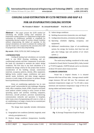
- 1. International Research Journal of Engineering and Technology (IRJET) e-ISSN: 2395 -0056 Volume: 04 Issue: 01 | Jan -2017 www.irjet.net p-ISSN: 2395-0072 © 2017, IRJET | Impact Factor value: 5.181 | ISO 9001:2008 Certified Journal | Page 1457 COOLING LOAD ESTIMATION BY CLTD METHOD AND HAP 4.5 FOR AN EVAPORATIVE COOLING SYSTEM Mr. Virendra V. Khakre1 Dr. Avinash Wankhade2 Prof. M. A. Ali3 ---------------------------------------------------------------------***--------------------------------------------------------------------- Abstract - This paper present the CLTD method for calculating the sensible cooling load estimation for evaporative cooling systems as a replacement of high power consuming air conditioners, partially or completely for maintaining thermal comfort in various climatic locations without compromising the indoor air quantity. In this manual calculations are made to estimate the cooling load and the results were compared by the outcomes from HAP 4.5 program for a three story shop building. Key words: - HVAC, CLTD, CLF, HAP, Cooling Load. 1 INTRODUCTION Cooling & heating load calculations are normally made to size HVAC (heating, ventilating, and air- conditioning) systems and their components. In principle, the loads are calculated to maintain the indoor design conditions. The first step in any load calculation is to establish the design criteria for the project that involves consideration of the building concept, construction materials, occupancy patterns, density, office equipment, lighting levels, comfort ranges, ventilations and space specific needs. Architects and other design engineers converse at early stages of the project to produce design basis & preliminary architectural drawings. Every air conditioning application has its own special „needs‟ and provided its own challenges. Shopping malls, office complexes, hotels, ATM’s, Airports and banks need uniform comfort cooling in every corners of their sprawling spaces and activities involving computers, electronics, aircraft products, precision manufacturing, communication networks and operation in hospitals, infect many areas of programming will come to a halt, so air conditioning is no longer a luxury but an essential part of modern part of modern living. The design basis typically includes information on: 1) Geographical site conditions (latitude, longitude, wind velocity, precipitation etc.) 2) Outdoor design conditions (temperature, humidity etc.) 3) Indoor design conditions 4) Building characteristics (materials, size, and shape) 5) Configuration (location, orientation and shading) 6) Operating schedules (lighting, occupancy, and equipment) 7) Additional considerations (type of air-conditioning system, fan energy, fan location, duct heat loss and gain, duct leakage, type and position of air return system…) 2 BUILDING LOCATION The multi-story building considered in this study is situated in Pusad, District Yavatmal (M.S.), India, located at 77.550E longitude, 19.890N latitude and at an elevation of about 315 meters above mean sea level. 3 CLIMATE CONDITION Pusad has a tropical climate; it is situated between hills from all four sides. Average annual rainfall ranges between 250 and 360 mm. The minimum and maximum temperatures ranges are 7 to 49 with a mean minimum and maximum temperature range of 9.8 to 42 during coldest and hottest months. Fig - 1: Average Temperature Graph for Pusad.
- 2. International Research Journal of Engineering and Technology (IRJET) e-ISSN: 2395 -0056 Volume: 04 Issue: 01 | Jan -2017 www.irjet.net p-ISSN: 2395-0072 © 2017, IRJET | Impact Factor value: 5.181 | ISO 9001:2008 Certified Journal | Page 1458 4 BUILDING STRUCTURE The dimension of the building which is to be air conditioned is, 10.59×6.12 m in size. It has three floors including the ground floor. The exterior walls of building consist of 102 mm face bricks and 203 mm face brick with 15 mm cement mortar sand 6 mm plaster on each side. The roof consists of 102 mm HW concrete with 6 mm plaster& air gap with pop 457 mm below the slab. The front display glass consists of single glass materials of 12 mm thick with frame panel. Table - 1: SUMMARY OF BUILDING SPECIFICATIONS 5 LOAD COMPONENTS The total heat required to be removed from the space in order to bring it at the desired temperature300C and relative humidity (50%) by the air conditioning equipment is known as cooling load or conditioned load. This load consists of external and internal loads. 5.1 External and Internal heat gains External heat gains arrive from the transferred thermal energy from outside hot medium to the inside of the room. The heat transfer takes place from conduction through external walls, top roof and bottom ground, solar radiation through windows and doors, ventilation and infiltration. Other sources are internal heat gain like people, electric equipment and light. Fig 1 illustrates the load components. Fig - 2: Load Components a. Sensible Heat Gain through Opaque Surface Q=UA (CLTD)corr Where, U = over all heat transfer coefficient (W/m2 0C) CLTD = cooling load temperature difference (0C) A = surface area (m2) Overall heat transfer coefficient CLTD corr = (CLTD + LM) K + (25.5 – Ti) + (To –29.4) Where, To = outside average temperature (0C) Ti = inside design temperature (0C) LM = latitude month correction K = correction factor depends on building color. K = 1 for dark color, 0.85 for medium color and 0.65 for light color. b. Heat Gain through Glass Transmission heat gain through glass Q=UA (CLTD) corr By solar radiation Q=A*SHGF max*SC*CLF Item Description Ground Floor 1st Floor 2nd Floor 1 Total Interior Space (Volume) 187.52 m2 187.52 m2 187.52 m2 2 Total Exterior Wall Area 82.53 m2 82.53 m2 82.53 m2 3 Total Roof Area 56.13 m2 56.13 m2 64.8 m2 4 Total Glass/ Window Area 7.36 m2 18.48 m2 18.48 m2 5 Number of Employees/ Staff 05 05 05 6 Number of visitors per hour 10 10 10 7 U value for wall 1.39 W/m2k 1.39 W/m2k 1.39 W/m2k 8 U value for Roof 1.68W/m2k 1.68 W/m2k 1.68 W/m2k 9 U value for Glass 2.21 Watt 2.21 Watt 2.21 Watt
- 3. International Research Journal of Engineering and Technology (IRJET) e-ISSN: 2395 -0056 Volume: 04 Issue: 01 | Jan -2017 www.irjet.net p-ISSN: 2395-0072 © 2017, IRJET | Impact Factor value: 5.181 | ISO 9001:2008 Certified Journal | Page 1459 Where SHGFmax= maximum solar heat gain factor (W/m2) SC= shading coefficient depends on type of shading CLF = cooling load factor c. Heat Gain from Occupants Sensible heat gain from occupants Qs person= qsperson * N * CLF Where Qs person= sensible heat gain/person (W) N = total number of people present in conditioned space CLF = cooling load factor d. Heat Gain from Lighting Equipment’s Qel = HGel * CLFel Qel= Cooling load from lighting, W HGel= Heat gain from lighting CLFel = Lighting cooling load factor HGel= W * Ful * Fsa W = Total light wattage Ful = Lighting use factor = 1 (for commercial appliances) Fsa= Lighting special allowance factor = 1.20 (for general application) e. Heat gain from electric equipment’s Qequipment = Total wattage of equipment * Use factor * CLF CLF = 1.0, if operation is 24 hours or of cooling is off at night or during weekends. f. Heat gain from office equipment’s Table - 2: Heat gain rate for office equipment’s (2001 ASHRAE Fundamentals Hand Book) Appliance Continuous Average Ideal Computer -15” Monitor -17” Monitor -19” Monitor 110 125 135 20 25 30 Laser printer-Desktop -Small office -Large office 130 320 550 100 160 275 10 70 125 Fax machine 30 Facsimile Machine 30 15 Image Scanner 25 15 Dot Matrix Printer 50 25 Desktop Copier 400 85 20 Office Copier 1100 400 300 g. Heat gain due to Infiltration Qinfiltration= Qsensible= 1.23 * Qinfiltration * ∆T h. Heat gain due to Ventilation Sensible load Qsensible = 1.23 * Q * (to-ti) Ventilation required = 1 L/sec/person To and Ti = Outside and inside design temperature respectively (0C) Table - 3: Manual Calculations for Sensible Load SR. No. Sensible Heat Gain Ground Floor 1st Floor 2nd Floor 1 Heat transfer through North side wall: 934.509 934.509 934.509 2 Heat transfer through West side wall: 999.270 999.270 999.270 3 Heat transfer through South side wall 783.207 783.207 783.207 4 Heat transferred through Glass by Radiation 2477.376 6220.37 6220.37 5 Heat transferred through Glass by Conduction 375.735 943.422 943.422 6 Heat transferred through Ceiling 992.984 942.984 1088.64 7 Heat transferred through Floor 1789.032 -- -- 8 Heat transferred through Plywood 276.006 276.006 276.006 9 Heat gain from people 1125 1125 1125 10 Heat gain from lighting equipment’s 432 432 432 11 Heat gain from Computer 200 -- -- 12 Heat gain from Printer 292 -- -- 13 Heat gain from Barcode Printer 370 -- -- 14 Heat gain from Fan 180 180 180 15 Heat gain from Door 740.09 -- -- 16 Ventilation 184.5 184.5 184.5 17 Infiltration rate 619.6 619.6 619.6 Total Load (kW) 12.76 kW 12.98 kW 13.12 kW 6. HOURLY ANALYSIS PROGRAM SOFTWARE 4.5 HAP is a computer tool which assists engineers in designing HVAC systems for commercial buildings. HAP is two tools in one. First it is a tool for estimating loads and designing systems. Second, it is a tool for simulating energy use and calculating energy costs. HAP uses the ASHRAE-endorsed transfer function method for load calculations and detailed 8,760 hour-by-hour energy simulation techniques for the energy analysis.
- 4. International Research Journal of Engineering and Technology (IRJET) e-ISSN: 2395 -0056 Volume: 04 Issue: 01 | Jan -2017 www.irjet.net p-ISSN: 2395-0072 © 2017, IRJET | Impact Factor value: 5.181 | ISO 9001:2008 Certified Journal | Page 1460 6.1 HAP system design features HAP estimates design cooling and heating loads for commercial buildings in order to determine required sizes for HVAC system components. Ultimately, the program provides information needed for selecting and specifying equipment. Specifically, the program performs the following tasks: Calculates design cooling and heating loads for spaces, zones, and coils in the HVAC system. Determines required airflow rates for spaces, zones and the system. Sizes cooling and heating coils. Sizes air circulation fans. Before design calculations can be performed types of information needed include: Climate data Construction material data for walls, roofs, windows, doors, exterior shading devices and floors, and for interior partitions between conditioned and non- conditioned regions. Size and layout data including wall, roof, window, door and floor areas, exposure orientations and external shading features. Internal load characteristics determined by levels and schedules for occupancy, lighting systems, equipment. Data concerning HVAC equipment, controls and components to be used. 6.2 HAP 4.5 Results Table - 4: HAP 4.5 Results Central Coil Sizing Data Sensible coil load Ground Floor 1st Floor 2nd Floor 12.6 kW 13.0 kW 13.0 kW 7. CONCLUSION In this paper the investigation on calculation of Sensible Cooling Load for Evaporative Cooling System has been conducted for two story shop building by CLTD method and HAP program produced by carrier for cooling load estimation was used to verify the results. The manual calculation results show that the total cooling load required for ground, first and second floor is 13.49 kW,14.36 kW and14.50 kW for summer (month of May). HAP result for the peak month (May) are 12.6 kW, 13.0 kW and 13.0 kW. The results were compared with manual calculations and it was noticed a dis-similarity between the two, because manual calculations considers peak value of the day whereas HAP gives weighted average value. References [1] ASHRAE 1997 HVAC Fundamentals Handbook. [2] ASHRAE 2001 HVAC Fundamentals Handbook. [3] Spitler, J.D., F.C. McQuiston, K. Lindsey. 1993. The CLTD/SCL/CLF Cooling Load Calculation Method, ASHRAE Transactions. 99(1): 183-192. [4] Cooling Load Calculations and Principles by A. Bhatiya. [5] Cooling and Heating load Calculation Manual: - Prepared by American society of Heating, Refrigerating and Air-conditioning engineers, Inc. BIOGRAPHIES Mr. Virendra V. Khakre, PG student, Department of Mechanical Engineering, B.N.C.O.E. Pusad. Dr. Avinash Wankhade, Professor & Head of Department, Department of Mechanical Engineering, B.N.C.O.E. Pusad. Prof. M. A. Ali Associate Professor, Department of Mechanical Engineering, B.N.C.O.E. Pusad.