Soosalu crustal structure_beneath_the_faroe_islands_from_teleseismic_receiver_functions
•
1 gefällt mir•257 views


Empfohlen
Weitere ähnliche Inhalte
Was ist angesagt?
Was ist angesagt? (20)
Andere mochten auch
Andere mochten auch (9)
Ähnlich wie Soosalu crustal structure_beneath_the_faroe_islands_from_teleseismic_receiver_functions
Ähnlich wie Soosalu crustal structure_beneath_the_faroe_islands_from_teleseismic_receiver_functions (20)
Mehr von Ingo Valgma
Mehr von Ingo Valgma (20)
Soosalu crustal structure_beneath_the_faroe_islands_from_teleseismic_receiver_functions
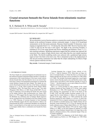
- 1. Geophys. J. Int. (2009) doi: 10.1111/j.1365-246X.2008.04018.x Crustal structure beneath the Faroe Islands from teleseismic receiver functions K. E. Harland, R. S. White and H. Soosalu∗ Bullard Laboratories, Department of Earth Sciences, University of Cambridge, CB3 0EZ, UK. E-mail: Kate.Harland@element-energy.co.uk Accepted 2008 November 3. Received 2008 October 28; in original form 2007 August 17 SUMMARY We use teleseismic receiver function analysis to constrain the crustal structure beneath the Faroe Islands on the northwest European volcanic continental margin. A cluster of 45 broad-band seismometers on the Glyvursnes peninsula, Streymoy Island recorded 10 teleseismic events ranging in magnitude from 6.1 to −8.0 during July–December 2003. Receiver functions show a clear Ps peak for the first time in this region. The depth of the converting boundary is estimated as 29–32 km using forward and inverse modelling and thickness versus V P /V S ratio stacking techniques. Modelling experiments suggest that this estimate may represent the conversion from a region of high-velocity lower crust rather than the crust–mantle transition at the Moho. The best-fit modelling results were achieved with a gradational high-velocity region at least 6 km thick in the lower crust. This is interpreted as due to the emplacement of sills into pre-existing continental crust rather than the simple underplating of a block of high velocity igneous material at its base. Key words: Continental margin; Crustal structure. GJI Seismology Lewisian basement has a typical P-wave velocity of 6.0– 1 I N T RO D U C T I O N 6.5 km s−1 (Hall & Simmons 1979). When there are large vol- The Faroe Islands are a presumed fragment of continental crust on umes of extruded basalts, it is likely that there is at least as much the northwest European continental margin, but there is currently no magma intruded into the lower crust as extruded (Cox 1980; White measurement of the crustal thickness or the lower crustal velocity et al. 2008). The intruded, fractionated magma has a much higher directly beneath them. Our first objective was to use receiver func- seismic velocity than the country rock, and therefore creates a high- tions from a cluster of 45 broad-band seismometers to constrain the velocity lower crust (HVLC) with velocities typically in excess of crustal thickness beneath the Faroe Islands. The islands are cov- 7.0 km s−1 . Our third objective was to seek evidence for an HVLC ered by flood basalts formed at the time of the Tertiary continental indicative of lower crustal intrusion. break-up at ca. 55 Ma, which created the North Atlantic (White Bott et al. (1974) provided an early estimate of the crustal & McKenzie 1989). The basalt flows reach at least 7 km thick thickness beneath the Faroe Islands of 27–38 km. Later authors (Waagstein 1988; White et al. 2003; Passey & Bell 2007). No out- (Richardson et al. 1998, 1999; Smallwood et al. 1999), using off- crops of underlying crust pre-dating the basalts have been found shore shooting into seismometers on land in the Faroes on the on the islands, however, plate reconstructions (e.g. Nunns 1983; FLARE, FAST and FIRE profiles (locations marked in Fig. 1), Knott et al. 1993) suggest that the region from East Greenland to suggest that the crustal thickness is likely to be towards the up- the Shetlands was continuous prior to breakup. Basalt sequences per end of this range. Staples et al. (1997) estimated the crustal can be correlated from east Greenland to the Faroe Islands (Larsen thickness beneath the Faroe Islands as 35–40 km, of which they et al. 1999). Outcrops of Lewisian basement in East Greenland interpreted 20–30 km as original continental crust and the remain- and the Shetlands suggest that the same basement is likely to be der as intruded or extruded igneous rock. Slightly thinner, but not found beneath the Faroes if continental lithosphere lies beneath the dissimilar crustal thicknesses of 27–32 km are reported from the basalt. A second objective of our study was to use receiver functions nearby submarine areas of Hatton Bank (White et al. 1987; Fowler to investigate whether there is continental crust beneath the Faroe et al. 1989), Rockall Bank (Bunch 1979) and the Fugloy Ridge Islands. (White et al. 2008). As the Faroe Islands are subaerial, we would expect the crustal thickness beneath them to be larger than on the adjacent, submarine portions of the continental margin if they are in isostatic equilibrium. ∗ Now at: Geological Survey of Estonia, Kadaka tee 82, 12618 Tallinn, Regions of HVLC are ubiquitous on the North Atlantic conti- Estonia. nental margins (e.g. Fowler et al. 1989; Morgan et al. 1989; White C 2009 The Authors 1 Journal compilation C 2009 RAS
- 2. 2 K. E. Harland, R. S. White and H. Soosalu Figure 1. Topographic map of the North Atlantic showing (inset) location of the seismometer cluster on the Faroese Island of Streymoy. Controlled source wide-angle seismic profiles near the Faroes Islands with whole crustal structure control are FIRE profile from Smallwood et al. (1999), FLARE profile from Richardson et al. (1998), FAST profile from Richardson et al. (1999) and iSIMM profile from White et al. (2008). & McKenzie 1989; Kelemen & Holbrook 1995; Barton & White Islands. Shaw Champion (2005) attempted to use data from a single 1997; Larsen & Saunders 1998; Vogt et al. 1998; Holbrook et al. seismometer on the Faroe Islands to calculate receiver functions, 2001; Korenaga et al. 2002; Hopper et al. 2003; Geoffroy 2005; but the data were noisy and they did not find a consistent converted Klingelhofer et al. 2005; Voss & Jokat 2007; White et al. 2008). arrival from the base of the crust. In our study we have used a tight The HVLC has often been referred to as ‘underplated’ igneous rock, cluster of 45 broad-band seismometers on Streymoy, Faroe Islands though as White et al. (2008) discuss, it is more likely to be a region (Fig. 1), which after stacking produces receiver functions with good of heavily intruded continental crust. signal-to-noise ratios and a clear converted arrival from the lower Comparisons of receiver function estimates of crustal structure crust. around the British Isles with wide-angle controlled source seismic constraints have been published by Tomlinson et al. (2006) and Shaw Champion et al. (2006). They report similar results from the two methods when the crustal velocity is known a priori, but also 2 RECEIVER FUNCTIONS show that it can be difficult to resolve the presence of an HVLC Receiver functions represent the seismic response beneath a seis- unless it is more than 4 km thick. For at least some of the locations, mometer to an incoming teleseismic P-wave. P-to-S conversions Tomlinson et al. (2006) suggest that the converting horizon from are generated at any interface with a significant velocity contrast which the thickness is calculated in the receiver function analysis (Fig. 2). The incident P waves have a steep angle of incidence (in represents the top of the HVLC rather than the Moho. The receiver this case 16–29◦ from the vertical for the direct P-wave and 8–16◦ function thickness is therefore smaller than the true crustal thick- from the vertical for their corresponding Ps conversions), hence the ness. Later in this paper we discuss the effect of an HVLC on the particle motion is polarized so that P waves dominate the vertical receiver functions from velocity profiles appropriate for the Faroe component and S waves are preferentially recorded on the radial C 2009 The Authors, GJI Journal compilation C 2009 RAS
- 3. Crustal structure beneath the Faroe Islands 3 Figure 2. Schematic ray paths for different labelled phases and multiples from a simple two-layer model with the resultant radial receiver function. component. The source time function of the event is removed from Figure 3. Changes in the timing and amplitudes of the main receiver func- tion phases shown in Fig. 2 for a simple two-layer model of the crust and the recorded teleseismic waveform by deconvolution, as described mantle with parameters appropriate for the Faroes region. (a) Effect of by Ammon (1991), in an attempt to isolate the conversions due change in crustal thickness h are in kilometres; (b) Effect of change in the to local structure from changes to the seismic waveform caused by V P /V S ratio of the crust. Multiple peaks, such as the PpPs peak, are delayed structure near the source and during propagation through the Earth’s differently for these two cases, and it is therefore possible to discriminate mantle between the source and the receiver. between them using the multiple phases. Receiver functions forward mod- We calculate receiver functions in the frequency domain using elled from these velocity models were generated using a Gaussian filter with codes by Ammon (1991), which are modified from Langston (1979). width a = 2 to match the inversions made subsequently on the observed A water-level method developed by Clayton & Wiggins (1976) is seismic data. used to fill spectral troughs and thereby produce stable receiver functions. A Gaussian low-pass filter was used during deconvolution functions are much smaller than the radial receiver functions, giving to remove high-frequency noise. The filter is given by us confidence in this assumption. 2 /4a2 ) G(ω) = e(−ω , (1) 3 F O RWA R D M O D E L S O F R E C E I V E R where a is a width factor of the filter. After preliminary trials with FUNCTIONS different values, a was set to 2.0. This produces a 90 per cent cut- off at 1 Hz on the high frequency side, to match the energy of the The depth to a converting boundary inferred from a receiver function teleseismic arrivals, which is predominantly below this frequency. depends on the P-wave velocity of the crust above that boundary The wavelength at 1 Hz is 6–7 km, so we do not expect to be able to and on the V P /V S ratio of the crust. The forward models of receiver resolve lower crustal layers thinner than about one half-wavelength, functions shown in Fig. 3 illustrate the changes in the traveltimes or 3–4 km in vertical thickness. and amplitudes of the main phases derived from a two-layer model We assume that the velocity structure is 1-D (i.e. there are no of the crust and mantle with changes in the thickness (Fig. 3a) and significant dips or lateral variability in the crustal structure over the the V P /V S ratio (Fig. 3b) of the crust. As can be seen from Fig. 3 it region extending approximately 15 km from the seismometer cluster is impossible to discriminate between the crustal thickness and the that is sampled by the different primary and multiple phases used in V P /V S ratio on the basis of the direct P and Ps arrivals alone, but the analysis and shown in Fig. 2.) In the absence of noise or lateral inclusion of multiple phases such as PpPs may allow their effects to variability there should be no energy on the tangential component be separated. We make use of this later in analysis of the observed of the receiver function. As we show later, the tangential receiver data. C 2009 The Authors, GJI Journal compilation C 2009 RAS
- 4. 4 K. E. Harland, R. S. White and H. Soosalu 3.1 Resolution of high-velocity lower crust (HVLC) type B, a gradational region of HVLC; and type C a high-velocity layer with a sharp top and a gradational base. These models (Fig. 4) In order to test which features of the HVLC can be resolved using were then used to generate synthetic radial receiver functions. For the receiver function method, we generated three types of simple each case the thickness z of the HVLC layer was varied from 0 crustal velocity profiles. They represent a simplified form of the to -9 km in 3-km steps. All results were compared with the receiver actual crustal velocity profile under the Faroe Islands, which has function generated by a control case, a simple two-layer model of basalts outcropping at the surface and no sedimentary overbur- the crust and mantle ( z = 0) with the boundary at 25 km below den. The type A crustal model contains a discrete layer of HVLC; the surface (which is also the top of the HVLC in all models). Figure 4. The model types A, B and C represent three possible crustal velocity models generated to investigate the resolution capabilities of the receiver function method. Receiver functions forward modelled from these velocity models were generated using a Gaussian filter with width a = 2 to match the inversions made subsequently on the observed seismic data. The ability to distinguish between a layer and a sharp discontinuity ( z = 0) is tested by varying z (0, 3, 6 and 9 km steps are depicted), and between a discrete layer and gradational region by comparing type A with type B and C receiver functions. The dominant phase conversion horizon in all these models is the top of the HVLC rather than the Moho, so depth estimates from receiver function inversions are likely to constrain the depth to the top of the HVLC rather than the Moho depth unless the HVLC is sufficiently thick to be recognized as a separate layer. Values of z in figure are in kilometres. C 2009 The Authors, GJI Journal compilation C 2009 RAS
- 5. Crustal structure beneath the Faroe Islands 5 The discrete HVLC (type A) is representative of a layer often depicted on crustal profiles, commonly termed ‘underplate’. The gradational HVLC (type B) may be formed if the lower crust is intruded by sills with the density and/or thickness of sills decreas- ing upwards away from the Moho. If only the lowermost crust is heavily intruded by high-velocity igneous sills, one might expect a greater contrast between the upper crust and the top of this intruded HVLC than between the HVLC and the underlying mantle below (as represented by type C crust). Experiments using type A crustal models demonstrate that a high-velocity lower crustal layer less than 6 km thick would be indistinguishable from the control two-layer case on the basis of the Ps peak alone, particularly in the presence of noise. Once the thickness z of the HVLC is increased above 6 km, two different Ps peaks from the bottom and top of a high-velocity layer can be resolved (Fig. 4a). These peaks have a delay time separation that is proportional to the thickness of the layer and amplitudes that depend on the magnitude of the velocity contrast across each boundary. The HVLC layer can be distinguished from the control case at a much smaller z using the PpPs peak. This has already split into two peaks on the multiple PpPs arrivals by z = 3 km. Receiver functions resulting from a gradational region at the base Figure 5. The 10 teleseismic events used in this receiver function study, of the crust are also hard to distinguish from the control two-layer plotted on a map centred on the Faroes. Numbers match details of earth- case or from a discrete high-velocity layer using the Ps peak alone quakes listed in Table 1. where z ≤ 6 km (Fig. 4b). The Ps peak does not split into two for greater z thicknesses, but in this case continues to broaden and within a 400 m by 400 m array on the Glyvursnes peninsula, Strey- to reduce in amplitude. The Ps peak does exhibit a slight increase moy, Faroe Islands (see Fig. 1). Ten teleseismic events selected for in delay time as z increases (by z = 9 km the delay time has receiver function analysis all had magnitudes ≥6.1, with angular increased by ca. 0.6 s). Changing the boundaries in the model from distances between 30◦ –90◦ (see Fig. 5 for locations and Table 1 for sharp to gradational results in a more obvious broadening of the details). They are clustered in back azimuth with four events near PpPs multiple peak and a decrease in its amplitude. This effect Japan, two in Siberia, three near the Aleutians and one lone event increases with increasing z. As the region thickens the PpPs peak on the Carlsberg Ridge. The small spatial extent of the seismometer is therefore more easily hidden by noise. cluster meant that it could not be used for array processing, but the The receiver functions generated from the type C profiles show a seismic data were stacked to improve the signal-to-noise ratio. combination of effects (Fig. 4c). The Ps peak remains similar to the control case in delay time (i.e. this peak is due to conversion from 4.2 Receiver functions the top of the layer), but it decreases in amplitude and broadens slightly as the thickness z of the gradational HVLC increases. Receiver functions were generated for each event, with all stations The PpPs multiple develops a distinct shape, a peak (resulting from in the cluster stacked. The resultant radial receiver functions show a reflection and then conversion from the top of the layer), with a consistent Ps peak, which is 3.5 ± 0.1 s after the direct P ar- a shoulder (as a result of the gradational region). The shoulder is rival (Fig. 6). In an ideal case, with flat isotropic horizontal layers, again of lower amplitude and would be easily obscured by noise in no energy from conversions should be recorded on the tangential real data. component. Dipping layers, anisotropy and scattered energy can, This analysis shows the importance of the PpPs multiple in con- however, all introduce energy. The tangential receiver functions straining the crustal structure, but also the difficulty of discriminat- from individual events show a significant amount of energy, but the ing between different models of the HVLC for thicknesses less than uneven distribution of events in back azimuth means that we cannot ca. 6 km. The receiver functions are governed by the depth of the constrain whether this is due to anisotropy or dipping layers, or is main layer at which phase conversion occurs, which in the models simply noise from local heterogeneity. we have used is dominantly at the top of the HVLC rather than at Receiver functions for individual events were stacked in clusters its base. The inferred crustal thickness from the receiver function of similar back azimuth, resulting in an improvement in the signal- method in the presence of an HVLC is likely therefore to be the to-noise ratio of the radial receiver functions (Fig. 6b). A clear Ps top of the HVLC rather than the Moho, unless the HVLC is thicker peak occurs at 3.5 ± 0.1 s, with a broader peak at 10.5 ± 0.4 s than 3–6 km and can be recognized as a separate layer at the base interpreted as the PpPs multiple, which becomes more apparent of the crust. after stacking. It is not possible to identify peaks later than this due to the background noise. The amplitudes of the corresponding tan- gential receiver functions are greatly reduced by stacking compared to those for individual events, suggesting that the majority of the 4 A N A LY S I S energy in the latter is a result of scattering or background noise rather than 3-D structure. For this reason a 1-D approximation is 4.1 Sources of data henceforth assumed. The stack of receiver functions from all events Forty-five Guralp 6TD seismometers (bandwidth 0.03–50 Hz) were achieved the best signal-to-noise ratio on the radial component with deployed during July–December 2003 in a tight cluster mainly least energy on the tangential component (Fig. 6c). C 2009 The Authors, GJI Journal compilation C 2009 RAS
- 6. 6 K. E. Harland, R. S. White and H. Soosalu Table 1. Events used for the receiver function study (data from United States Geological Survey/National Earthquake Information Center). Depth Ray Parameter Backazimuth Event Date Origin time Location MW (km) (◦ ) 1 16/06/2003 22:08:02 Kamchatka, Aleutians 6.9 175 0.0601 8 2 29/09/2003 02:36:53 Hokkaido, Japan 6.5 25 0.0534 22 3 25/09/2003 19:50:08 Hokkaido, Japan 8.0 33 0.0532 22 4 27/07/2003 06:25:32 near SE coast of Russia 6.8 470 0.0554 24 5 25/07/2003 22:13:30 E. coast Honshu, Japan 6.1 6 0.0512 25 6 01/10/2003 01:03:25 SW Siberia 6.7 10 0.0691 58 7 27/09/2003 11:33:25 SW Siberia 7.5 17.6 0.0690 58 8 15/07/2003 20:27:50 Carlsberg Ridge 7.6 10 0.0449 104 9 17/11/2003 06:43:06 Andreanof Is., Aleutians 7.8 33 0.0574 356 10 23/06/2003 12:12:34 Rat Islands, Aleutians 6.9 20 0.0576 358 5 C RU S TA L S T RU C T U R E F R O M a low-velocity zone (remaining inversions). The velocity gradient O B S E RV E D R E C E I V E R F U N C T I O N S increases again in the lowermost quarter of the crust beneath 25 km depth (all inversions show this). We used three different methods to constrain the crustal structure The velocities of 4.5–6.5 km s−1 and the high-velocity gradient from the stacked receiver functions. First, we made an inversion in the upper 10 km of the crust are consistent with the thick-layered using Ammon’s (1991) method. Second, we made a grid search basalt sequence seen everywhere on the Faroe Islands, which is using a h − V p /V s stacking method developed by Zhu & Kanamori known from outcrop and drilling to be at least 7 km thick. The low- (2000). Third, we forward modelled the main phases by hand to fit velocity zone beneath this could be real, and would then represent the amplitudes and relative arrival times of the main phases. The continental crust. It may also be an artifact of the limited bandwidth difference between these methods is primarily in the way that noise of the seismometers that may cause artificial negative peaks in the affects the results: the inversion weights all the parts of the waveform receiver functions which then translate into low-velocity zones in equally irrespective of their source, whereas forward modelling by the inversion. Even if the actual velocities do not decrease, but hand enables us to concentrate explicitly just on those phases that rather exhibit a greatly reduced velocity gradient in the mid-crust, we can identify, while ignoring other parts of the waveform that may we would still interpret this as due to the presence of continental be noise. In the following section we discuss the overall constraints crust beneath the Faroes, overlain by extrusive basalts. The structure on crustal structure that can be inferred from the results of applying of the Fugloy Ridge derived from wide-angle controlled source these three different methods to the same data. seismic profiles (red dotted line in Fig. 7), which lies along strike from the Faroes shows a similar velocity profile that is interpreted by White et al. (2008) as representing continental crust overlain by 5.1 Inverse modelling basalts. Note that the Fugloy Ridge is submarine, and has lost some The programs used for inversion modelling are described by of the near-surface basaltic section by erosion, so it is not surprising Ammon (1991). Ammon’s inversions use a Poisson’s ratio of 0.25 that it now has a thinner overall crustal thickness of 27 km than the throughout. Modified versions of the programs were therefore cre- subaerial Faroe Islands. ated to allow the V P /V S ratio to be input into the velocity model The increase in velocity gradient in the lower 10 km of the crust is layer -by-layer and hence to allow variation with depth for greater exactly what we would expect to be produced by igneous intrusions geological realism. Controlled source wide-angle seismic profiles in the lower crust. were used to generate an approximate starting velocity model, then this was perturbed randomly multiple times and the inversion was 5.2 h − V P /V S stacking completed for each perturbed input model. In Fig. 7 we show the mean velocity-depth profile from these multiple inversions for each This method, after Zhu & Kanamori (2000), stacks receiver func- of the regionalized input receiver functions (coloured lines in Fig. 7), tions in the crustal thickness h − V P /V S ratio domain. Arrival as well as for the stack of all events (thicker black line in Fig. 7). times of the Ps, PpPs and PpSs + PsPs phases are calculated for P-wave velocities of ca. 7.6 km s−1 , which are typical of mantle each receiver function, using the appropriate ray parameter for that rocks are reached at a depth of about 32 km beneath the surface. This event, and across a range of values of h and V P /V S ratios. The stack also corresponds to a change to a smaller velocity gradient at the is produced by summing the amplitudes of each receiver function same depth (broken horizontal black line in Fig. 7), which therefore at each of these traveltimes. The advantage of this method is that makes it a good candidate for the Moho. The precise details of we only stack signals at the time when we expect arrivals. However, the variations in velocity structure below 32 km are beyond the the disadvantage is that in the presence of noise, the signal at the resolution of the inversion, and the smoothing necessary for the expected traveltimes of the PpPs and PpSs + PsPs phases may be inversion forces boundaries to be gradational in the modelling, so dominated by noise because the arrivals from the teleseismic event we conclude that the best estimate for the crustal thickness from are only small in any case; we would then be stacking noise, not this method is about 32 km. signal. The variation of ray parameter from the different events is The overall structure of the 32-km thick crust is marked by a high- 0.045–0.069 (Table 1). We experimented with a realistic range of velocity gradient in the upper 10 km, beneath which there is either different values of the average crustal P-wave velocity and found a decrease in velocity gradient (as shown by inversion of arrivals that the stacks are rather insensitive to the precise value adopted, from the Carlsberg Ridge), or an actual decrease in velocity causing since they depend mainly on the traveltime difference between the C 2009 The Authors, GJI Journal compilation C 2009 RAS
- 7. Crustal structure beneath the Faroe Islands 7 Figure 6. (a) Radial (left) and tangential (right) receiver functions for each event (see Table 1 for details). (b) Receiver functions, grouped and stacked by back azimuth as annotated. The Ps peak stands out more clearly, noise is reduced and the amplitudes of the tangential receiver functions are reduced significantly by the stack. (c) Stack of all events, which markedly reduces energy on the tangential receiver function. Positive amplitudes are shaded. See Fig. 2 for definitions of P, Ps and PpPs phases. phases. In the final stack result shown in Fig. 8 we use an average the continental basement rock of Lewisian Gneiss, which may have crustal velocity of 6.5 km s−1 . a V P /V S ratio as low as 1.73 (Christensen 1996). A likely overall The maximum value of the stack using our data is for a crustal crustal average beneath the Faroes is 1.78 (Christensen 1996; Eccles thickness of 26 km, with a V P /V S ratio of 1.88 (Fig. 8), but there et al. 2008). The red line in Fig. 8 shows the range of inferred is a trade-off in the highest values of h − V P /V S shown by the crustal thickness of 27–31 km using the two extremes V P /V S diagonal band across Fig. 8. An average crustal V P /V S ratio of ratios of basalt and Lewisian Gneiss, with the thickness from the 1.88 is unrealistic for the rock types likely to be present beneath the most likely value of V P /V S being about 29 km (red dot in Fig. 8). Faroe Islands. Basalt has the highest V P /V S ratio of the lithologies As Tomlinson et al. (2006) have shown from synthetic studies of present, measured as typically 1.84 from boreholes in the Faroes h − V P /V S stacking, any departure from the assumed 1-D crustal and from wide-angle seismic measurements (Christie et al. 2006; velocity structure (for example, a dipping Moho), would affect the Eccles et al. 2007, 2008; Bais et al. 2008), while the other extreme is delay times and amplitudes of the peaks and lead to an underestimate C 2009 The Authors, GJI Journal compilation C 2009 RAS
- 8. 8 K. E. Harland, R. S. White and H. Soosalu Figure 7. Mean velocity models generated from multiple inversions with randomized starting velocity models from event stacked receiver functions (solid coloured lines as annotated in figure). Thicker black line shows mean velocity model from a receiver function stack of all the events. Red dotted line is velocity structure from the submarine Fugloy Ridge which lies along strike from the Faroe Islands (from White et al. 2008). Dotted line at 32 km depth marks best estimate of the crustal thickness based on the change in velocity gradient at this depth, and the increase in P-wave velocity above 7.6 km s−1 . of fit of the synthetic seismograms was judged by its agreement with the relative timing, amplitude and width of each observed peak. The latter was particularly useful for multiple phases, for example the width of PpPs arrivals are diagnostic of gradational velocities in the lower crust (Fig. 4). V P /V S ratios appropriate for the crust under the Faroe Islands were assumed as described in the previous section. A preliminary study was carried out using a two-layer model of the crust and mantle. For subsequent studies the minimum number of layers was used that created an adequate fit to the different peaks. Adding a low velocity top layer to the model generated the trough, which commonly follows the direct P peak. This layer represents the basalt flows that outcrop on the island. The P-wave velocity of this layer was chosen on the basis of borehole data (Petersen et al. 2006; Bais et al. 2008) and is therefore well constrained. However, the negative lobes around the main arrivals may also be artifacts of the receiver function generation caused by limited bandwidth of the seismometers (0.03–50 Hz). The width of the Figure 8. Contour plot of the thickness versus V P /V S ratio from all re- peaks was poorly modelled by a sharp crust–mantle discontinuity. ceiver functions, calculated by summing the amplitudes of Ps, PpPs and A gradational velocity increase at the same depth resulted in a PpSs+PsPs phases. The band of highest amplitudes shows the trade-off definite broadening of the multiple peak, improving the match to between thickness and V P /V S ratio. Realistic estimates of V P /V S ratio the data (as expected from Fig. 4). ranging from 1.73 (Lewisian Gneiss) to 1.84 (basalt) are marked by the red The best-fit velocity model produced by forward modelling the line, with a most likely whole-crustal value of 1.78 constraining the depth stack of all receiver functions is shown in Fig. 9. Similar velocity to the main converting interface as 29 ± 2 km. models were produced for individual receiver functions and suggest that the base of the crust is marked by a gradational region of the of the crustal thickness in this stacking technique. The best crustal order of 4–6 km thick with the Moho at a depth of about 30 km. thickness of 29 ± 2 km may therefore be a slight underestimate of the true thickness, or may represent conversion of the top of the HVLZ as we showed in the forward modelling (Fig. 4). 6 DISCUSSION 5.3 Forward modelling We consistently find evidence from the three methods described Forward modelling using the reflectivity method (Kennett 1983), above for a crustal thickness of 29–32 km beneath the Faroe Is- was carried out by hand. We aimed to fit the amplitudes and relative lands. The mid-crustal velocities are consistent with the presence timing of the three main peaks produced by the direct P, Ps and of continental crust similar to that inferred beneath the along-strike PpPs phases and where possible to also fit a negative peak that may continental fragments of Fugloy Ridge (White et al. 2008), Hat- represent the PpSs+PsPs conversion. The noise level of the signal ton Bank (Fowler et al. 1989; Morgan et al. 1989) and Edoras prevented identifying and fitting any further multiples. The quality Bank (Barton & White 1997). This continental crust lies beneath an C 2009 The Authors, GJI Journal compilation C 2009 RAS
- 9. Crustal structure beneath the Faroe Islands 9 Figure 9. The best forward-model fit to the receiver function generated from a stack of all events. The shallowest layer in the velocity model represents a basalt layer and has considerable impact on the first few seconds of the receiver function. There is a good match to the delay time, the width and the amplitude of the Ps peak. The broad PpPs multiple is matched by the choice of a gradational HVLC region at the base of the crust. upper layer about 10 km thick with velocities of 4.5–6.5 km s−1 and 7.6 km s−1 , although when there is such a large amount of igneous a high-velocity gradient which is interpreted as extrusive basalts. intrusion it becomes a moot point whether to interpret this as heav- There is evidence for an HVLC at the base of the crust. Fur- ily intruded continental crust or as upper mantle. In any case, we thermore, it appears to be gradational over a thickness of about expect there to be at least as much intruded igneous rock as ex- 6–10 km. If a discrete layer of high-velocity lower crust with a truded basalts on this volcanic continental margin, consistent with strong impedance contrast (an ‘underplated’ region) were present, our results. it would have to be less than 6 km thick to fit the observed Ps peak in the receiver functions. The PpPs peak observed is poorly mod- elled by such a layer, and we conclude from our modelling that a AC K N OW L E D G M E N T S gradational HVLC is more likely. We interpret this as caused by the We thank Sj´ rdur Patursson, on whose land we deployed the array, u intrusion of igneous sills into the lower crust, with the density of Mike Worthington, Morten Sparre-Andersen, Nick Mohammed and sills increasing downwards towards the Moho. the students from the Universities of Cambridge and the Faroe The crustal thickness we infer of 29–32 km is within the uncer- Islands who helped with fieldwork, and Trine Dahl-Jensen for her tainty estimates of thicknesses from wide-angle Moho reflections reviews. The SeiFaBa project was funded by the Sindri Group. to the east and west of the Faroe Islands, although it is at the lower Department of Earth Sciences, Cambridge contribution no. ES9305. end of those estimates. Our Faroe Island estimates are also sim- ilar to crustal thicknesses of 27 km and 35 km calculated from receiver functions from the conjugate east Greenland coastal area at Ittoqqortoormiit in Scoresbysund and Sodalen, respectively (Dahl- Jensen et al. 2003; Kumar et al. 2007). The receiver function method REFERENCES relies on mode conversion to define boundaries, and therefore it is Ammon, C.J., 1991. The isolation of receiver effects from teleseismic P possible that the crustal thickness we estimate is actually the depth waveforms, Bull. seism. Soc. Am., 81, 2504–2510. to a region within the HVLC where there are significant velocity Bais, G., White, R.S., Worthington, M.H., Andersen, M.S. & Seifaba Group, contrasts rather than to the top of the mantle. This would be consis- 2008. Seismic properties of Faroe basalts from borehole and surface data, tent with the apparent thinnest crust derived from receiver functions Faroe Islands Exploration Conference: Proceedings of the 2nd Confer- on the conjugate east Greenland coastal region being for stations ly- ence, Annales Societatis Scientiarum Færoensis, Supplementum, 95, 59– ing directly above the track of the Iceland plume, where the thickest 75. HVLC and concomitantly thicker crust overall would be expected. Barton, A.J. & White, R.S., 1997. Crustal structure of Edoras Bank conti- nental margin and mantle thermal anomalies beneath the North Atlantic, In the Ethiopian Rift, which is an analogous region of early conti- J. geophys. Res., 102, 3109–3129. nental breakup above a mantle plume, Stuart et al. (2006) report that Bott, M.H.P., Sunderland, J., Smith, P.J., Casten, U. & Saxov, S., 1974. receiver function results underestimate the crustal thickness due to Evidence for continental crust beneath the Faeroe Islands, Nature, 248, phase conversions from a layer of HVLC. Our inversions shown 202–248. in Fig. 7 suggest that there could be several kilometres of highly Bunch, A.W.H., 1979. A detailed seismic structure of Rockall Bank—a intruded rock beneath 32 km depth with velocities in excess of synthetic seismogram analysis, Earth planet. Sci. Lett., 45, 453–463. C 2009 The Authors, GJI Journal compilation C 2009 RAS
- 10. 10 K. E. Harland, R. S. White and H. Soosalu Christensen, N.I., 1996. Poisson’s ratio and crustal seismology, J. geophys. Morgan, J.V Barton, P.J. & White, R.S., 1989. The Hatton Bank continental ., Res., 101(B2), 3139–3156. margin—III. Structure from wide-angle OBS and multichannel seismic Christie, P., Gollifer, I. & Cowper, D., 2006. Borehole seismic studies of a refraction profiles, J. geophys. Res., 98, 367–384. volcanic succession from the Lopra-1/1A Borehole in the Faroe islands, Nunns, A.G., 1983. Plate tectonic evolution of the Greenland-Scotland ridge NE Atlantic, Geo. Denmark Surv., 9, 23–40. and surrounding regions, in Structure and Development of the Greenland- Clayton, R.W. & Wiggins, R.A., 1976. Source shape estimation and de- Scotland Ridge, pp. 11–30, eds Bott, M.H.P., Saxov, S., Talwani, M. & convolution of teleseismic body waves, Geophys. J. R. astr. Soc., 47, Thiede, J., Plenum Press, New York. 151–177. Passey, S.R. & Bell, B.R., 2007. Morphologies and emplacement mecha- Cox, K.G., 1980. A model for flood basalt vulcanism, J. Petrol., 21, 629–650. nisms of the lava flows of the Faroe Islands Basalt Group, Faroe Islands, Dahl-Jensen, T. et al., 2003. Depth to Moho in Greenland: receiver-function NE Atlantic Ocean, Bull. Volc., 70, 139–156. analysis suggests two Proterozoic blocks in Greenland, Earth planet. Sci. Petersen, U.K., Andersen, M.S., White, R.S. & SeiFaBa Group, 2006. Seis- Lett., 205, 379–393. mic imaging of basalts at Glyvursnes, Faroe Islands: hunting for fu- Eccles, J.D., White, R.S., Roberts, A.W., Christie, P.A.F. & the iSIMM Team ture exploration methods in basalt covered areas, First Break, 24, 45– 2007. Wide angle converted shear wave analysis of a North Atlantic 51. volcanic rifted continental margin: constraint on sub-basalt lithology, Richardson, K.R., Smallwood, J.R., White, R.S., Snyder, D.B. & Maguire, First Break, 25.10, (October 2007), 63–70. P.K.H., 1998. Crustal structure beneath the Faroe Islands and the Faroe- Eccles, J.D., White, R.S., Christie, P.A.F., Roberts, A.W. & iSIMM Team, Iceland Ridge, Tectonophysics, 300, 159–180. 2008. Insight into sub-basalt lithology from wide-angle converted shear Richardson, K.R., White, R.S., England, R.W. & Fruehn J., 1999. Crustal wave analysis, Faroe Islands Exploration Conference: Proceedings of the structure east of the Faroe Islands: mapping sub-basalt sediments using 2nd Conference, Annales Societatis Scientiarum Froensis, Supplementum wide-angle seismic data, Petroleum Geoscience, 5, 161–172. 48. Shaw Champion, M.E., 2005. Influence of the Iceland plume on crustal Fowler, S.R., White, R.S., Spence, G.D. & Westbrook, G.K., 1989. The Hat- structure and uplift of the British Isles, PhD dissertation, University of ton Bank continental margin–II. Deep structure from two-ship expanding Cambridge. spread seismic profiles, Geophys. J. Int., 96, 295–309. Shaw Champion, M.E., White, N.J., Jones, S.M. & Priestley, K.F., 2006. Geoffroy, L., 2005. Volcanic passive margins, C. R. Geoscience, 337, 1395– Crustal velocity structure of the British Isles: a comparison of receiver 1408. functions and wide-angle seismic data, Geophys. J. Int., 166, 795– Hall, J. & Simmons, G., 1979. Seismic velocities of Lewisian metamorphic 813. rocks at pressures to 8 kbar: relationship to crustal layering in north Smallwood, J.R., Staples, R.K., Richardson, K.R. & White, R.S., 1999. Britain, Geophys. J. R. astr. Soc., 58, 337–347. Crust generated above the Iceland mantle plume; from continental rift to Holbrook, W.S. et al., 2001. Mantle thermal structure and active upwelling oceanic spreading center, J. geophys. Res., 104, 22 885–22 902. during continental breakup in the North Atlantic, Earth Planet. Sci. Lett., Staples, R.K., White, R.S., Brandsdottir, B., Menke, W., Maguire, P.K.H. & 90, 251–266. McBride, J.H., 1997. Faroe-Iceland Ridge Experiment, 1. Crustal struc- Hopper, J.R., Dahl-Jensen, T., Holbrook, W.S., Larsen, H.C., Lizzaralde, ture of northeastern Iceland, J. geophys. Res., 102, 7849–7866. D., Korenaga, J., Kent, G.M. & Kelemen, P.B., 2003. Structure of Stuart, G.W., Bastow, I.D. & Ebinger, C.J., 2006. Crustal structure of the the SE Greenland margin from seismic reflection and refraction data: northern Ethiopian Rift from receiver function studies, Geo.Soc. Spec. implications for nascent spreading center subsidence and asymmetric Publ., 259, 253–267. crustal accretion during North Atlantic opening, J. geophys. Res., 5, Tomlinson, J.P., Denton, P., Maguire, P.K.H. & Booth, D.C., 2006. Analysis doi:10.1029/2002JB001996. of the crustal velocity structure of the British Isles using teleseismic Kelemen, P.B. & Holbrook, W.S., 1995, Origin of thick, high-velocity crust receiver functions, Geophys. J. Int., 167, 223–237. along the US East Coast margin, J. geophys. Res., 100, 10 077–10 094. Vogt, U., Makris, J., O’Reilly, B.M., Hauser, F., Readman, P.W., Jacob, Kennett, B.L.N., 1983. Seismic Wave Propagation in Stratified Media, Cam- A.W.B. & Shannon, P.M., 1998. The Hatton Basin and continental margin: bridge University Press, New York. crustal structure from wide-angle seismic and gravity data, J. geophys. Korenaga, J., Kelemen, P.B. & Holbrook, W.S., 2002. Methods for resolving Res., 103(B6), 12 545–12 566. the origin of large igneous provinces from crustal seismology, J. geophys. Voss, M. & Jokat, W., 2007. Continent-ocean transition and volumi- Res., 107(B9), doi:10.1029/2001BJ001030. nous magmatic underplating derived from P-wave velocity modelling Klingelhofer, F., Edwards, R.A., Hobbs, R.W. & England, R.W., 2005. of the East Greenland continental margin, Geophys. J. Int., 170, 580– Crustal structure of the NE Rockall Trough from wide-angle seismic data 604. modeling, J. geophys. Res., 110, B11105, doi:10.1029/2005JB003763. Waagstein, R., 1988. Structure, composition and age of the Faeroe basalt Knott, S.D., Burchell, M.T., Jolley, E.J. & Fraser, A.J., 1993. Mesozoic to plateau, in Early Tertiary Volcanism and the Opening of the NE Atlantic, Cenozoic plate reconstructions of the North Atlantic and tectonostrati- Vol. 39, pp. 225-238, eds Morton, A.C. & Parson, L.M., Geol. Soc., graphic history of the UKCS Western Margin, in Proceedings of the 4th London, Spec. Publn. Petroleum Geology Conference: Petroleum Geology of Northwest Europe, White, R. & McKenzie, D., 1989. Magmatism at rift zones: The generation pp. 953–974, ed. Parker, J.R., Geological Society, London. of volcanic continental margins and flood basalts, J. geophys. Res., 94, Kumar, P., Kind, R., Priestley, K. & Dahl-Jensen, T., 2007. Crustal structure 7685–7729. of Iceland and Greenland from receiver function studies, J. geophys. Res., White, R.S. et al., 1987. Hatton Bank (northwest U.K.) continental margin 112, B03301–B03319, doi:10.1029/2005JB003991. structure, Geophys. J. Int., 89, 265–272. Langston, C.A., 1979. Structure under Mount Rainer, Washington, inferred White, R.S., Smallwood, J.R., Fliedner, M.M., Boslaugh, B., Maresh, J. & from teleseismic body waves, J. geophys. Res., 84, 4749–4762. Fruehn, J., 2003. Imaging and regional distribution of basalt flows in the Larsen, H.C. & Saunders, A.D., 1998. Tectonism and volcanism at the Faroe-Shetland Basin, Geophys. Prospect., 51, 215–231. southeast Greenland rifted margin: a record of plume impact and later White, R.S., Smith, L.K., Roberts, A.W., Christie, P.A.F., Kusznir, N.J. & continental rifting, in Proc. ODP Sci. Results,Vol. 152, pp. 503–533, eds , iSIMM Team, 2008. Lower-crustal intrusion on the North Atlantic conti- Saunders, A.D., Larsen, H.C. & Wise, S.W. Jr., Ocean Drilling Program, nental margin, Nature, 452, 460–464 (supplementary information avail- College Station, TX, able at www.nature.com). Larsen, L.M., Waagstein, R., Pedersen, A.K. & Storey, M., 1999. Trans- Zhu, L. & Kanamori, H., 2000. Moho depth variation in Southern Cali- Atlantic correlation of the Palaeogene volcanic successions in the Faroe fornia from teleseismic receiver functions, J. geophys. Res., 105, 2969– Islands and East Greenland, J. Geol. soc. Lond., 156, 1081–1095. 2980. C 2009 The Authors, GJI Journal compilation C 2009 RAS