SlideShare ist ein Scribd-Unternehmen logo
1 von 214
PROFILER 2™ Reference Guide
The Water Tank Alternative


                                          s
                                          u
Your Most Valuable QA & Dosimetry Tools   n
Reference Guide, PROFILER 2™
     © Copyright 2005-2008 by Sun Nuclear Corporation. All rights reserved.
     The information contained in this technical manual and the accompanying software program is
     protected by copyright and all rights are reserved by Sun Nuclear Corporation. Copying, duplicat-
     ing, selling, or otherwise distributing any part of this product without the prior written consent of
     Sun Nuclear Corporation is prohibited.
     Sun Nuclear Corporation reserves the right to make periodic modifications of this product without
     obligation to notify any person or entity of such revision.
     This guide is written for:
              PC software:                         version 1.3
              Firmware:                            version 1.2.4
     PROFILER 2™, Profiler™, IC PROFILER™, SRS PROFILER™, Daily QA3™, and ATLAS QA™ are
     trademarks of Sun Nuclear Corporation. Other trademarks or trade names are the property of their
     respective owners.
     Any changes or modifications not expressly approved by Sun Nuclear Corporation could void the
     user's authority to operate this equipment.
     Document 1174011, Rev F, 22 August 2008


                                                                 Sun Nuclear Corporation
                                                                 425A Pineda Court
                                                                 Melbourne, Florida 32940-7508
                                                                 telephone + 1 321-259-6862
                                                                 fax +1 321-259-7979
                                                                 e-mail: contactus@sunnuclear.com
                                                                 http://www.sunnuclear.com


                                  Sun Nuclear Corporation is an ISO 13485:2003 registered company


                                  EMERGO EUROPE
                                  Molenstraat 15
                                  2513 BH, The Hague
                                  The Netherlands
                                  Phone: +31.70.345.8570
                                  Fax: +31.70.346.7299


ii
Preface
                 This section provides information about the latest PROFILER 2 firmware version (1.2.4), lists the
                 new features in PROFILER 2 software version 1.3, describes the conventions used in the PRO-
                 FILER 2 documentation, and lists safety instructions for using the PROFILER 2.

Firmware Version 1.2.4

                 Firmware version 1.2.4 or higher must be installed on the PROFILER 2 for proper operation with
                 software release 1.3. If firmware version 1.2.4 or higher is not installed on the device, the user is
                 prompted that a firmware update is required to save array calibrations or dose calibrations to flash
                 memory.
                 Firmware version 1.2.4 also allows the software to automatically read device information (such as
                 hardware version, product ID, and serial number) without accessing the device memory directly.
                 The latest PROFILER 2 firmware can be downloaded from the Sun Nuclear Corporation web site,
                 www.sunnuclear.com. See “Installing Firmware” on page 19 for installation instructions.

Software Version 1.3


                              Note: For software version 1.3 to operate properly, new firmware must be installed.
                              See “Firmware Version 1.2.4” .


                 Version 1.3 of PROFILER 2 software adds the following new features:

          Data Plot View
                 The View panel has a new tab, Data Plot. The Data Plot view provides a visual display of beam
                 analysis parameters over the duration of the measurement. It can be used with saved files or real-
                 time. The plottable options are flatness, beam center, field size, point symmetry, dose per Pulse,
                 pulses/sec, dose rate, reference value, sensor voltage (or distance), and TPR (dose at depth). The
                 Data Plot view is only for multi-frame files,

          Import Water Tank Measured Files
                 Water tank data can now be imported into the software. The imported data can be displayed, com-
                 pared, and manipulated using any of the PROFILER 2 tools. The supported import filters include
                 Pinnacle (Philips), Mephysto (PTW), and OmniPro (Welhoffer).

          Smoothing
                 The Control > Smooth Data menu option invokes a gaussian smoothing algorithm which is
                 applied to the data before display/analysis. The extent of the smoothing is selected in the ‘Setup
                 Parameters’ dialog box. This option is disabled by default.

          Analysis Panel Changes
                 •    The analysis panel now provides a horns parameter for photon beams and 90% electron posi-
                      tion parameter for electron beams. The horns parameter shows the percent difference
                      between the left horn and CAX in one panel, and the percent difference between the right
                      horn and CAX in another panel. The 90% electron parameter display shows the outermost
                      position on the left and right of the value which is 90% of the maximum found within the
                      profile.
                 •    The Varian acceptance formula for flatness has been added to the flatness options.


Preface                                                                                                             iii
Beam Edge Interpolation
            The default beam edge interpolation method has been improved. This arctangent method is more
            accurate than the previous linear penumbra interpolation method. The user can still select the lin-
            ear method in the Setup Parameters, if desired.

     Invert X and Y-Axes
            When ‘Invert’ is selected, the X-axis and Y-axis profiles of the selected file are inverted 180 degrees
            horizontally on the graph. In previous software releases only the Y profile was inverted.

     Top Plate Field Size Compensation
            A new option in the Configure Analysis dialog box allows the software to factor in the inherent
            buildup of the attached device when reporting the measured field size for calculating light/radia-
            tion field coincidence. If enabled, the software reports the field size at the detector plane;
            otherwise, it reports the field size at the overlay.

     Prompt to Resave if Files are Changed
            The software automatically detects if changes have been made to a file header, array calibration,
            or dose calibration, and when the user closes the window it prompts the user to “re-save”.

     Automatically Find Device
            When the software is launched it automatically searches all ports for an attached device.

     Zoom Options
            •   A button has been added to the Data toolbar that allows the user to normalize all displayed
                graphs to physical center and zoom to the 85-110% view.
            •   A new option in the ‘Setup Parameters’ dialog box allows the user to select if zoom will be
                permitted along the vertical and horizontal scales, or if only the vertical axis should be zoomed
                and the horizontal axis should remain fixed at the length of the array.

     File Name Suggestioning
            When saving data, the software will automatically suggest a file name based on the current date.
            The user can modify the file name, if desired.

     Set Energy Quicklist
            A ‘set energy’ option has been added to the Setup menu. The user can select an energy from the
            quick list, or choose the option to enter a custom value. The energy can also be selected using
            the Analysis panel context (right-click) menu.

     Array Calibration Improvements
            •   The Array Calibration ‘Results’ window now displays a legend to identify the profile for each
                step of the calibration.
            •   The on-screen array calibration instructions have been modified for clarity.
            •   When calculating calibrated detectors by Field Size, the Array Calibration window displays the
                selected region with a blue box over the graphical template.
            •   Array calibration files can be saved in a format that is compatible with older versions of ATLAS
                QA software.

     Default Mode and Data Type
            If the first file opened is a single file (*.prs) and it contains a dose calibration factor, the data type
            will default to Dose; otherwise the default data type is Normalized. If the first file opened is a multi-
            frame file (*.prm), the mode will default to Inst. Rate; otherwise the default mode is Total Dose.

     Orientation Offsets when Exporting in SNC ASCII
            When exporting data in SNC ASCII format, the export dialog now includes an option to apply ori-
            entation offsets to the data. If this option is selected, the orientation offsets specified in the file
            header are applied to the detector positions before the data is exported.


iv                                                                                                           Preface
User Definable Background Collection Time
                  The background collection time is now user-configurable. The range is from 10 to 600 seconds,
                  and the default is 20 seconds.

          User Definable Collection Interval
                  The sampling time (time between updates) can now be defined in the Setup Parameters dialog
                  box. There are separate settings for continuous radiation and pulsed radiation.

          On-Graph Display Toolbar
                  •   An On-Graph Display toolbar has been added to the left side of the view panel. This toolbar
                      contains buttons with graphical representations of the axes display options, such as all four
                      axes, primary axes only, diagonal profiles only, or an individual axis.
                  •   The On-Graph Display toolbar to the left of the view panel also provides a new drop down
                      menu to select the type of analysis parameter that will be displayed in the Graph view and
                      Data view. The options are: None, Beam Center, Point Values, CAX Point Difference, Local
                      Point Difference, Point Ratio, Varian Point Difference, Area Average, and Area. The options in
                      bold type are new in this software release.
                  •   The On-Graph Display toolbar has a Project to 100cm checkbox which adjusts all loaded pro-
                      files to 100 SSD before analysis and display.

Conventions

          Button Name or Entry
                  Bold typeface indicates the following:
                  •   A button name (i.e.,”…click the Edit button”), OR
                  •   An entry that the user must type (i.e., “Enter the username ADMIN...”), OR
                  •   An item for which an entry must be selected and the entry itself (i.e., “...select Photon from
                      the Type list box...”

          Manual Titles
                  Italicized typeface indicates the title of a manual (i.e., “See the Reference Guide or Online Help...”).

          Menu Options
                  Bold italicized typeface indicates a menu option (i.e., “...select Setup > Preferences from the
                  menu”).

          User Messages/Cross References
                  Text within double quotes indicates the following:
                  •   A message displayed to the user (i.e., “...the message “Your devices are ready to use” is dis-
                      played in the taskbar.”), OR
                  •   A cross referenced subsection in this manual (i.e., “...see “Measurement Buttons” on page...”

          Window/Dialog Box Names
                  Text within single quotes indicates a window or dialog box name (i.e., “...the ‘Program Prefer-
                  ences’ dialog box is displayed.”

Symbols

                  The following symbols are used in this document and in Sun Nuclear Corporation’s product labels.


                       !       WARNING: Possible impact to personal safety.


Preface                                                                                                                 v
!       CAUTION: Important notation.


                        Note: Important or supporting information.


                        Go To: Provides guidance for which procedure to perform next.


                        Manufacturer’s Identification (name and address).


                        Date of Manufacture.


                        Serial Number.


                        Catalog Number.


                        Consult instructions for use.


                            Authorized representative in the European Community.


Operating Information

            •   Read the entire manual before using the product.
            •   Use the product only within normal laboratory conditions maintained for human comfort: 18
                to 30° C (64 to 86° F), 20 to 80% relative humidity.
            •   This unit is not to be used as a standard during the calibration of a radiation source. However,
                the device can be calibrated to read absolute dose using data from a known source.
            •   If the device cannot be calibrated to match the readings of a known standard, return it to the
                manufacturer for repair.
            •   In this manual, CAUTIONS are used to indicate the possibility of damage to equipment.
            •   Inspect cables periodically for damage. Return damaged cables to Sun Nuclear Corporation
                for repair or replacement if any mechanical or electrical degradation is suspected.


vi                                                                                                      Preface
Safety Instructions

             Read and follow the following common-sense safety instructions:
             •   Do not use the equipment with any power that does not match the power ratings listed on
                 the power supply.
             •   Do not permit water or any other liquids to spill onto or into the instrument or associated
                 equipment.
             •   Do not permit any short circuit of AC power that may be hazardous to users.
             •   Do not use any power cord or power supply that is damaged or has broken insulation. Replace
                 them immediately.
             •   To protect insulation, never pull on the cable to disconnect the power cord from a wall socket;
                 always grasp the plug.
             •   Do not open or disassemble any device. Access to the inside of the device is for trained per-
                 sonnel only. There are no user-repairable parts inside. Return all devices to the factory for
                 repair.
             •   When connected to AC power, position the device so that the plug is easily disconnected and
                 is not obstructed.

Warnings and Cautions


                         CAUTION: Any changes or modifications not expressly approved by Sun Nuclear Cor-
                 !       poration could void the user’s authority to operate this equipment.


Preface                                                                                                        vii
This page is intentionally left blank.


viii                                            Preface
Contents
Preface . . . . . . . . . . . . . . . . . . . . . . . . . . . . . . iii                  Setting Up the USB Port . . . . . . . . . . . . . . . . . . . .           15
  Firmware Version 1.2.4 . . . . . . . . . . . . . . . . . . . . . . iii                    USB Drivers for Windows Vista . . . . . . . . . . . .                  15
  Software Version 1.3 . . . . . . . . . . . . . . . . . . . . . . . . iii                  USB Drivers for Windows XP and 2000 . . . . . .                        18
     Data Plot View . . . . . . . . . . . . . . . . . . . . . . . . . . iii                 Verifying Installation of USB Drivers. . . . . . . . .                 19
     Import Water Tank Measured Files . . . . . . . . . . iii                               Removing the USB Drivers . . . . . . . . . . . . . . . .               19
     Smoothing . . . . . . . . . . . . . . . . . . . . . . . . . . . . . iii             Installing Firmware . . . . . . . . . . . . . . . . . . . . . . . .       19
     Analysis Panel Changes . . . . . . . . . . . . . . . . . . . iii                    Setting up the Serial Port. . . . . . . . . . . . . . . . . . . .         20
     Beam Edge Interpolation . . . . . . . . . . . . . . . . . . iv                      Launching the Software and Connecting . . . . . . .                       20
     Invert X and Y-Axes. . . . . . . . . . . . . . . . . . . . . . . iv                    Launching Software . . . . . . . . . . . . . . . . . . . . .           20
     Top Plate Field Size Compensation . . . . . . . . . . iv                               Finding the Port . . . . . . . . . . . . . . . . . . . . . . . .       20
     Prompt to Resave if Files are Changed . . . . . . . iv                                     Find Device . . . . . . . . . . . . . . . . . . . . . . . . .      20
     Automatically Find Device . . . . . . . . . . . . . . . . . iv                             To Select a Specific Port . . . . . . . . . . . . . . .            20
     Zoom Options. . . . . . . . . . . . . . . . . . . . . . . . . . . iv                Connecting Multiple Instruments . . . . . . . . . . . . .                 21
     File Name Suggestioning . . . . . . . . . . . . . . . . . . iv                      Shutdown. . . . . . . . . . . . . . . . . . . . . . . . . . . . . . . .   21
     Set Energy Quicklist . . . . . . . . . . . . . . . . . . . . . . iv                 Removing PROFILER 2 Software . . . . . . . . . . . . .                    21
     Array Calibration Improvements. . . . . . . . . . . . . iv                             Software Removal (Windows Vista) . . . . . . . . .                     21
     Default Mode and Data Type . . . . . . . . . . . . . . . iv                            Software Removal (Windows XP) . . . . . . . . . . .                    21
     Orientation Offsets when Exporting in SNC ASCII
                                                                                     Section 3. About PROFILER 2 Software . . . .                                  23
         iv
                                                                                       Graphical User Interface . . . . . . . . . . . . . . . . . . . .            23
     User Definable Background Collection Time . . . v
                                                                                       Menu Options . . . . . . . . . . . . . . . . . . . . . . . . . . . .        24
     User Definable Collection Interval . . . . . . . . . . . v
                                                                                       File Menu Options . . . . . . . . . . . . . . . . . . . . . . . . .         26
     On-Graph Display Toolbar . . . . . . . . . . . . . . . . . v
                                                                                           Import > Planned Dose . . . . . . . . . . . . . . . . . .               26
  Conventions. . . . . . . . . . . . . . . . . . . . . . . . . . . . . . . v
                                                                                               Options > Dose Map Orientation . . . . . . . .                      27
     Button Name or Entry. . . . . . . . . . . . . . . . . . . . . v
                                                                                           File > Import >Watertank Measured. . . . . . . .                        28
     Manual Titles . . . . . . . . . . . . . . . . . . . . . . . . . . . v
                                                                                               Select a Profile to Display Dialog Box . . . . .                    28
     Menu Options. . . . . . . . . . . . . . . . . . . . . . . . . . . v
                                                                                               PT Data Offsets Dialog Box . . . . . . . . . . . . .                29
     User Messages/Cross References. . . . . . . . . . . v
                                                                                           File > Export > SNC ASCII . . . . . . . . . . . . . . . .               29
     Window/Dialog Box Names . . . . . . . . . . . . . . . . v
                                                                                           File > Export> DQA Measurement . . . . . . . . .                        30
  Symbols. . . . . . . . . . . . . . . . . . . . . . . . . . . . . . . . . . v
                                                                                           File > Export > ADAC ASCII. . . . . . . . . . . . . . .                 31
  Operating Information . . . . . . . . . . . . . . . . . . . . . . . vi
                                                                                           Edit > Edit Header . . . . . . . . . . . . . . . . . . . . . .          32
  Safety Instructions . . . . . . . . . . . . . . . . . . . . . . . . vii
                                                                                               Editing the File Header. . . . . . . . . . . . . . . . .            35
  Warnings and Cautions . . . . . . . . . . . . . . . . . . . . . vii
                                                                                               Using Default Header Entries . . . . . . . . . . .                  35
Section 1. About the Instrument. . . . . . . . . . .                             1         Tools > Collect Background. . . . . . . . . . . . . . .                 35
  Intended Use . . . . . . . . . . . . . . . . . . . . . . . . . . . . . .       1         Tools > Calibrate Array. . . . . . . . . . . . . . . . . . .            36
  Description . . . . . . . . . . . . . . . . . . . . . . . . . . . . . . .      1             Edit SSD and Field Size . . . . . . . . . . . . . . . .             37
  Features. . . . . . . . . . . . . . . . . . . . . . . . . . . . . . . . . .    2             Array Calibration Dialog Box (During
  Applications. . . . . . . . . . . . . . . . . . . . . . . . . . . . . . .      2             Calibration) . . . . . . . . . . . . . . . . . . . . . . . . . .    38
     More Applications . . . . . . . . . . . . . . . . . . . . . . .             2         Tools > Calibrate Dose. . . . . . . . . . . . . . . . . . .             39
  Parts and Accessories. . . . . . . . . . . . . . . . . . . . . . .             3         Tools > Download Code . . . . . . . . . . . . . . . . .                 40
  Setup Overview . . . . . . . . . . . . . . . . . . . . . . . . . . . .         4         Tools > Save Calibration to Flash. . . . . . . . . . .                  40
  Construction . . . . . . . . . . . . . . . . . . . . . . . . . . . . . .       5         Tools > Concatenate . . . . . . . . . . . . . . . . . . . .             41
     Precision Template. . . . . . . . . . . . . . . . . . . . . . .             6         Setup > Parameters . . . . . . . . . . . . . . . . . . . . .            42
  End Panel. . . . . . . . . . . . . . . . . . . . . . . . . . . . . . . . .     7         Setup > Analysis . . . . . . . . . . . . . . . . . . . . . . .          43
  Power/Data Interface (P/DI). . . . . . . . . . . . . . . . . . .               7         Setup > Set Energy . . . . . . . . . . . . . . . . . . . . .            46
  Cables . . . . . . . . . . . . . . . . . . . . . . . . . . . . . . . . . . .   8         Setup > View Calibration . . . . . . . . . . . . . . . . .              46
  Finding Additional Information . . . . . . . . . . . . . . . .                 8         Setup > Electron Wedge Calibration . . . . . . . .                      47
     Using Online Help. . . . . . . . . . . . . . . . . . . . . . . .            8         Setup > Wedge Configuration . . . . . . . . . . . . .                   48
  Specifications . . . . . . . . . . . . . . . . . . . . . . . . . . . . .       9         Setup > Serial Port . . . . . . . . . . . . . . . . . . . . . .         49
                                                                                           Help > About . . . . . . . . . . . . . . . . . . . . . . . . . .        49
Section 2. Software Setup . . . . . . . . . . . . . .                        13
                                                                                       Context Menus . . . . . . . . . . . . . . . . . . . . . . . . . . .         50
  Overview . . . . . . . . . . . . . . . . . . . . . . . . . . . . . . . .   13
                                                                                       Toolbar Area. . . . . . . . . . . . . . . . . . . . . . . . . . . . . .     51
  Single Installation . . . . . . . . . . . . . . . . . . . . . . . . .      13
                                                                                           Acquisition Toolbar . . . . . . . . . . . . . . . . . . . . . .         51
  Multiple Installations . . . . . . . . . . . . . . . . . . . . . . .       13
                                                                                           Display Toolbar . . . . . . . . . . . . . . . . . . . . . . . . .       52
  USB Connection . . . . . . . . . . . . . . . . . . . . . . . . . .         14
                                                                                           Dose Calibration Toolbar . . . . . . . . . . . . . . . . .              52
  Serial Connection . . . . . . . . . . . . . . . . . . . . . . . . .        14
                                                                                           Array Calibration Toolbar . . . . . . . . . . . . . . . . .             52
         Serial Connection with P/DI . . . . . . . . . . . . .               14
                                                                                           Data Toolbar . . . . . . . . . . . . . . . . . . . . . . . . . . .      53
         Serial Port Alternatives . . . . . . . . . . . . . . . .            15


Contents                                                                                                                                                           ix
Status Toolbar . . . . . . . . . . . . . . . . . . . . . . . . . 53              Viewing a Saved Calibration File. . . . . . . . . . . . 92
       Movie Player Toolbar . . . . . . . . . . . . . . . . . . . . 54                  Calculating Calibrated Detectors for Small Fields
       On Graph Display Toolbar . . . . . . . . . . . . . . . . 54                          93
    Legend Panel. . . . . . . . . . . . . . . . . . . . . . . . . . . . . 55            Selecting Calibrated Detectors By Field Size . . 93
       Legend Panel Details . . . . . . . . . . . . . . . . . . . . 55                  Selecting Calibrated Detectors By Profile Shape .
    View Panel . . . . . . . . . . . . . . . . . . . . . . . . . . . . . . . 57             93
    Graph View . . . . . . . . . . . . . . . . . . . . . . . . . . . . . . 58         Dose Calibration . . . . . . . . . . . . . . . . . . . . . . . . . . 94
       Graph View Details . . . . . . . . . . . . . . . . . . . . . . 58                Adding a Dose Measurement. . . . . . . . . . . . . . 94
       Data Points . . . . . . . . . . . . . . . . . . . . . . . . . . . . 59           Saving a Dose Calibration To Flash . . . . . . . . . 96
       Graph Scale . . . . . . . . . . . . . . . . . . . . . . . . . . . 59             Changing the Dose Calibration Factor . . . . . . . 96
       Zoom. . . . . . . . . . . . . . . . . . . . . . . . . . . . . . . . . 59         Setting Up A Default Dose Calibration . . . . . . . 96
       Hiding a Profile . . . . . . . . . . . . . . . . . . . . . . . . . 60            Removing A Dose Calibration Value . . . . . . . . . 96
       Normalizing the Graph . . . . . . . . . . . . . . . . . . . 61                   Subtract Background . . . . . . . . . . . . . . . . . . . . 97
          If Normalization Settings Do Not Match Data                                 Recalibration Interval . . . . . . . . . . . . . . . . . . . . . . . 97
          Type . . . . . . . . . . . . . . . . . . . . . . . . . . . . . . . 61
                                                                                  Section 5. Measuring Radiation . . . . . . . . . . 99
       On Graph Symmetry. . . . . . . . . . . . . . . . . . . . . 61
                                                                                    Positioning PROFILER 2 . . . . . . . . . . . . . . . . . . . . 99
       Graph View Context Menu . . . . . . . . . . . . . . . . 62
                                                                                    Loading Calibration References . . . . . . . . . . . . . . 99
    Header View . . . . . . . . . . . . . . . . . . . . . . . . . . . . . 62
                                                                                       Array Calibration File . . . . . . . . . . . . . . . . . . . . . 99
       Copy and Paste Header Fields . . . . . . . . . . . . . 63
                                                                                       Dose Calibration Value . . . . . . . . . . . . . . . . . . 100
       Header View Context Menu . . . . . . . . . . . . . . . 63
                                                                                    Inherent Buildup and Physical Depth . . . . . . . . . 101
    Data View . . . . . . . . . . . . . . . . . . . . . . . . . . . . . . . 64
                                                                                    Measuring A Single Profile . . . . . . . . . . . . . . . . . 101
    Beam Tuning View . . . . . . . . . . . . . . . . . . . . . . . . 66
                                                                                       Starting the Profile Measurement . . . . . . . . . 101
    Data Plot View . . . . . . . . . . . . . . . . . . . . . . . . . . . . 68
                                                                                       Checking the Gain. . . . . . . . . . . . . . . . . . . . . . 101
       Plot Settings Details . . . . . . . . . . . . . . . . . . . . . 69
                                                                                       Saving the Profile . . . . . . . . . . . . . . . . . . . . . . 102
    Analysis Panel . . . . . . . . . . . . . . . . . . . . . . . . . . . . 70
                                                                                    Multiple Frame Capture . . . . . . . . . . . . . . . . . . . . 103
       Analysis Panel Details . . . . . . . . . . . . . . . . . . . 70
                                                                                       Collecting Multiple Frame Data . . . . . . . . . . . 103
       Changing the Analysis Panel Elements . . . . . . 72
                                                                                    Concatenating Two Measurements . . . . . . . . . . 103
       Editing the Analysis Panel Parameters. . . . . . . 73
                                                                                       Concatenation Procedure . . . . . . . . . . . . . . . . 104
          Edit Field Parameters . . . . . . . . . . . . . . . . . 73
                                                                                    Continuous Radiation . . . . . . . . . . . . . . . . . . . . . 106
          Edit Penumbra Parameters . . . . . . . . . . . . . 74
                                                                                    Checking Electron Energy With a Wedge . . . . . . 106
          Edit Light Field and SSD Parameters . . . . . 74
                                                                                       Electron Energy Wedge Setup . . . . . . . . . . . . 106
          Edit Flatness Parameters. . . . . . . . . . . . . . . 74
                                                                                       Electron Energy Wedge Calibration . . . . . . . . 106
          Edit Symmetry Parameters . . . . . . . . . . . . . 75
                                                                                          Collect Data . . . . . . . . . . . . . . . . . . . . . . . . 106
          Edit Energy Analysis Parameters. . . . . . . . . 75
                                                                                          Load Electron Energy Files . . . . . . . . . . . . 107
          Edit Wedge Parameters. . . . . . . . . . . . . . . . 76
                                                                                          To Add a New Calibration Set . . . . . . . . . . 107
          Edit Configuration Parameters . . . . . . . . . . 76
                                                                                          Apply Calibration . . . . . . . . . . . . . . . . . . . . 108
       Setting the Machine Energy in the Header . . . 77
                                                                                       Taking a Measurement . . . . . . . . . . . . . . . . . . 108
       Changing the Analysis Panel Position . . . . . . . 78
                                                                                    Photon Wedge Measurements . . . . . . . . . . . . . . 109
       Hiding Items . . . . . . . . . . . . . . . . . . . . . . . . . . . 78
                                                                                    Beam Tuning . . . . . . . . . . . . . . . . . . . . . . . . . . . . 110
    Drag and Drop Positioning . . . . . . . . . . . . . . . . . . 78
                                                                                       Overview . . . . . . . . . . . . . . . . . . . . . . . . . . . . . 110
Section 4. Calibrating the System. . . . . . . . .                         81          Using the Beam Tuning Display . . . . . . . . . . . 110
  Array Calibration . . . . . . . . . . . . . . . . . . . . . . . . . .    81       Data Analysis Using the Data Plot. . . . . . . . . . . . 111
     Array Calibration Fixture . . . . . . . . . . . . . . . . . .         81          Overview . . . . . . . . . . . . . . . . . . . . . . . . . . . . . 111
     Background Measurements . . . . . . . . . . . . . . .                 82          Using the Data Plot Display . . . . . . . . . . . . . . 111
        Automatic Background . . . . . . . . . . . . . . . .               82       Data Interpretation. . . . . . . . . . . . . . . . . . . . . . . . 112
        Manual Background. . . . . . . . . . . . . . . . . . .             82
                                                                                  Section 6. Viewing Files and Printing . . . . . 113
     Array Calibration Conditions. . . . . . . . . . . . . . .             82
                                                                                    Opening and Saving Files . . . . . . . . . . . . . . . . . . 113
  Array Calibration Procedure . . . . . . . . . . . . . . . . .            83
                                                                                       Selecting File Type . . . . . . . . . . . . . . . . . . . . . 113
     Calibration Setup . . . . . . . . . . . . . . . . . . . . . . .       83
                                                                                       Saving Measured Data . . . . . . . . . . . . . . . . . . 114
     Calibration Steps . . . . . . . . . . . . . . . . . . . . . . .       84
                                                                                       Duplicating a File . . . . . . . . . . . . . . . . . . . . . . 114
        Overview . . . . . . . . . . . . . . . . . . . . . . . . . . .     84
                                                                                       Re-Opening a File . . . . . . . . . . . . . . . . . . . . . . 114
        Step A . . . . . . . . . . . . . . . . . . . . . . . . . . . . .   84
                                                                                       Closing a File. . . . . . . . . . . . . . . . . . . . . . . . . . 114
        Step B . . . . . . . . . . . . . . . . . . . . . . . . . . . . .   85
                                                                                       Clearing a File . . . . . . . . . . . . . . . . . . . . . . . . . 114
        Step C . . . . . . . . . . . . . . . . . . . . . . . . . . . . .   86
                                                                                       Hiding a File . . . . . . . . . . . . . . . . . . . . . . . . . . 114
        Step D . . . . . . . . . . . . . . . . . . . . . . . . . . . . .   87
                                                                                    Changing Colors . . . . . . . . . . . . . . . . . . . . . . . . . 114
     Viewing the Array Calibration Results . . . . . . .                   88
                                                                                    Comparing Profiles . . . . . . . . . . . . . . . . . . . . . . . 115
     Saving the Array Calibration File. . . . . . . . . . . .              89
                                                                                    Movie Playback . . . . . . . . . . . . . . . . . . . . . . . . . . 116
     Saving Array Calibration to Flash Memory . . . .                      89
                                                                                    Reports . . . . . . . . . . . . . . . . . . . . . . . . . . . . . . . . 117
     Calibration with Saved Files . . . . . . . . . . . . . . .            90
                                                                                       Print Options . . . . . . . . . . . . . . . . . . . . . . . . . . 117
     Loading a Saved Calibration File . . . . . . . . . . .                91
                                                                                       Printing Reports . . . . . . . . . . . . . . . . . . . . . . . 119


x                                                                                                                                                 Contents
Printing Screens . . . . . . . . . . . . . . . . . . . . . . . 119            Import Filter Updates . . . . . . . . . . . . . . . . . . .          150
                                                                                    Importing Water Tank Measured Files . . . . . . . .                    150
Section 7. Importing/Exporting Data. . . . . . 121
                                                                                      Water Tank File Import Procedure . . . . . . . . .                   151
  Importing Planned Dose Files . . . . . . . . . . . . . . . 121
                                                                                    Exporting Data . . . . . . . . . . . . . . . . . . . . . . . . . . .   152
     Import Filter . . . . . . . . . . . . . . . . . . . . . . . . . . 121
                                                                                      SNC ASCII Export . . . . . . . . . . . . . . . . . . . . . .         153
     TPS Dose Maps . . . . . . . . . . . . . . . . . . . . . . . 121
                                                                                         From Menu. . . . . . . . . . . . . . . . . . . . . . . . .        153
     About Dose Maps . . . . . . . . . . . . . . . . . . . . . 121
                                                                                         By Copying . . . . . . . . . . . . . . . . . . . . . . . . .      153
     Import Filter - Supported File Types. . . . . . . . 122
                                                                                      DQA3 Measurement Export . . . . . . . . . . . . . .                  154
        About EPIDose Files . . . . . . . . . . . . . . . . . 122
                                                                                      Pinnacle Export . . . . . . . . . . . . . . . . . . . . . . . .      154
        About DICOM Files . . . . . . . . . . . . . . . . . . 122
                                                                                         Header fields . . . . . . . . . . . . . . . . . . . . . . .       154
     PROFILER 2 Plan Grid Resolution . . . . . . . . . 122
                                                                                         Data Orientation . . . . . . . . . . . . . . . . . . . . .        155
     Preparing Dose Maps for Import . . . . . . . . . . 123
                                                                                         Wedge and Circular Collimator . . . . . . . . .                   155
     Exporting 3D Line ERGO++ Files . . . . . . . . . 123
                                                                                         Export Procedure . . . . . . . . . . . . . . . . . . . .          155
     Exporting AccuKnife AccuSoft XL Files . . . . . 124
     Exporting Pinnacle3 (Philips) Files . . . . . . . . . 124                  Section 8. Interpreting Measurements . . . . 157
     Exporting BrainLAB Brain Scan Files . . . . . . . 127                        Assuring Accurate Measurements . . . . . . . . . . . 157
     Exporting CMS Files . . . . . . . . . . . . . . . . . . . . 127                 Calibration . . . . . . . . . . . . . . . . . . . . . . . . . . . . 157
        Focus and XIO files . . . . . . . . . . . . . . . . . . 127                  Reporting Hardware or Software Faults . . . . . 157
        Generate a General Dose Plan Export File 127                              Calibration Concepts . . . . . . . . . . . . . . . . . . . . . . 157
        Generate a Beam Map File Using the Decimal                                   Array Calibration . . . . . . . . . . . . . . . . . . . . . . . 157
        Utility . . . . . . . . . . . . . . . . . . . . . . . . . . . . . 128        Calibration Files. . . . . . . . . . . . . . . . . . . . . . . . 157
     Exporting Elekta Precise Plan Files . . . . . . . . 129                         Theory of Calibration Using Wide Fields . . . . 158
     Exporting Memorial Sloan Kettering Cancer Care                               Profile Storage And Data Format. . . . . . . . . . . . . 159
        Files . . . . . . . . . . . . . . . . . . . . . . . . . . . . . . 129        Saving a Profile . . . . . . . . . . . . . . . . . . . . . . . . 159
     Exporting MDS Nordion Helax TMS Files . . . 130                                 PROFILER 2 File Formats . . . . . . . . . . . . . . . . 159
        Overly Complex DICOM File Format . . . . . 130                               SRS Profiler File Formats . . . . . . . . . . . . . . . . 159
     Exporting NOMOS CORVUS Files . . . . . . . . . 131                              Profiler 1 File Formats. . . . . . . . . . . . . . . . . . . 160
     Exporting Nucletron Files . . . . . . . . . . . . . . . . 131                Analysis of a Profile . . . . . . . . . . . . . . . . . . . . . . . 160
        Nucletron PLATO File . . . . . . . . . . . . . . . . 131                     Field Size . . . . . . . . . . . . . . . . . . . . . . . . . . . . . 162
        Nucletron Oncentra TP File . . . . . . . . . . . . 132                       Beam Center . . . . . . . . . . . . . . . . . . . . . . . . . . 163
     Exporting PerMedics Odyssey Files . . . . . . . 133                             Light/Radiation Field Coincidence . . . . . . . . . 163
     Exporting Prowess Panther Files . . . . . . . . . . 134                         Penumbra . . . . . . . . . . . . . . . . . . . . . . . . . . . . 163
     Exporting Radionics XKnife Files . . . . . . . . . . 134                        Flatness. . . . . . . . . . . . . . . . . . . . . . . . . . . . . . 163
     Exporting RAHD Alpha 3D Pro Files. . . . . . . . 136                                Flatness Calculation by Variance . . . . . . . . 163
     Exporting Siemens KonRad Files . . . . . . . . . . 136                              Ratio (IEC) Flatness Calculation . . . . . . . . . 164
     Exporting TGM ARTP (Topslane) Files . . . . . . 137                                 Varian Flatness Calculation . . . . . . . . . . . . 164
     Exporting Varian Files . . . . . . . . . . . . . . . . . . . 137                Symmetry . . . . . . . . . . . . . . . . . . . . . . . . . . . . 164
        CadPlan File . . . . . . . . . . . . . . . . . . . . . . . . 137                 CAX Point Difference Symmetry . . . . . . . . 165
        Eclipse File. . . . . . . . . . . . . . . . . . . . . . . . . 138                Local Point Difference Symmetry . . . . . . . 165
     Exporting Files in DICOM File Format . . . . . . 138                                Point Ratio (Ratio IEC) Symmetry . . . . . . . 165
        DICOM CR image file . . . . . . . . . . . . . . . . 139                          Varian Point Difference Symmetry. . . . . . . 166
     Exporting Files in SunCOM File Format . . . . . 139                                 Area Average Symmetry . . . . . . . . . . . . . . 166
     SunCOM File Specification. . . . . . . . . . . . . . . 139                          Area Symmetry . . . . . . . . . . . . . . . . . . . . . 167
        SunCOM Optional Header Information . . . 140                              Horn Values . . . . . . . . . . . . . . . . . . . . . . . . . . . . . 167
        SunCOM Required Keywords . . . . . . . . . . 140                          90% Position . . . . . . . . . . . . . . . . . . . . . . . . . . . . 168
        Example SunCOM File. . . . . . . . . . . . . . . . 141                    Beam Interpolated Flatness and Symmetry . . . . 168
     Using the PROFILER 2 Import Filter. . . . . . . . 141                        Beam Edge Interpolation . . . . . . . . . . . . . . . . . . . 169
     Aligning Plan Dose Maps to PROFILER 2 . . . 142                              Smoothing . . . . . . . . . . . . . . . . . . . . . . . . . . . . . . 169
        Beam Center Offset. . . . . . . . . . . . . . . . . . 143                 Calculating Calibrated Detectors For Small Fields . .
        Rotation . . . . . . . . . . . . . . . . . . . . . . . . . . . 143        169
     Measuring an Equivalent Profile. . . . . . . . . . . 144                     Profile Comparison . . . . . . . . . . . . . . . . . . . . . . . 170
     Import Window Display . . . . . . . . . . . . . . . . . 145                     Percent Difference . . . . . . . . . . . . . . . . . . . . . 170
        TPS Import Window Menu Options . . . . . 145                                 Compare Index . . . . . . . . . . . . . . . . . . . . . . . . 170
        TPS Import Window Toolbar . . . . . . . . . . . 145                       Data Type and Mode Selection . . . . . . . . . . . . . . 171
     Inverting Imported Files . . . . . . . . . . . . . . . . . 146                  Overview . . . . . . . . . . . . . . . . . . . . . . . . . . . . . 171
        Check for Dose Map Inversion . . . . . . . . . 147                               Normalized . . . . . . . . . . . . . . . . . . . . . . . . . 171
     Excluding Import Filters . . . . . . . . . . . . . . . . . 148                  Inst Rate and Avg Rate Modes. . . . . . . . . . . . 171
     Importing a Slice Or Volume File . . . . . . . . . . 148                        Concatenated And Double Profiles . . . . . . . . 172
     TPS File Import - Troubleshooting . . . . . . . . . 149                      Electron Energy Wedge Analysis . . . . . . . . . . . . 172
        Opening Plan Files. . . . . . . . . . . . . . . . . . . 149                  Electron Energy Calculated by Slope Analysis 172
        Error Messages . . . . . . . . . . . . . . . . . . . . . 149


Contents                                                                                                                                                    xi
Electron Energy Calculated by Intercept Analysis .                            Detector Layout and Geometry . . . . . . . . . . . 182
            172                                                                     ATLAS QA Test Plan . . . . . . . . . . . . . . . . . . . . . . 182
      Photon Energy Wedge Analysis . . . . . . . . . . . . . 173                      Importing a PROFILER 2 Array Calibration File 183
        Calculation 1 . . . . . . . . . . . . . . . . . . . . . . . . . . 173         Setting up the Scheme Tree . . . . . . . . . . . . . . 184
        Calculation 2 . . . . . . . . . . . . . . . . . . . . . . . . . . 173         Setting Up the Template for Beam Tracking . 185
        Calculation 3 . . . . . . . . . . . . . . . . . . . . . . . . . . 173         Calibrating the QA Template . . . . . . . . . . . . . 186
      Real Time Studies During Accelerator Adjustment . .                           Measurement with ATLAS QA . . . . . . . . . . . . . . 187
      174                                                                             Preparing for Measurement . . . . . . . . . . . . . . 187
        Compare in Accelerator QA . . . . . . . . . . . . . . 174
                                                                                Section 11. Maintaining Your System. . . . . 191
        Fixed Wedge QA . . . . . . . . . . . . . . . . . . . . . . 175
                                                                                  Maintaining Hardware . . . . . . . . . . . . . . . . . . . . . 191
        Moving (Dynamic, Virtual) Wedge QA . . . . . . 175
                                                                                     Parts and Repairs . . . . . . . . . . . . . . . . . . . . . . 191
      About Profile Acquisition. . . . . . . . . . . . . . . . . . . 175
                                                                                     Storage . . . . . . . . . . . . . . . . . . . . . . . . . . . . . . 191
        Radiation Measurement . . . . . . . . . . . . . . . . . 175
                                                                                     Cleaning . . . . . . . . . . . . . . . . . . . . . . . . . . . . . 191
Section 9. PROFILER 2 Accessories . . . . . .                             177        Disposal and Recycling. . . . . . . . . . . . . . . . . . 191
  Isocentric Mounting Fixture (IMF). . . . . . . . . . . .                177     Maintaining Software and Firmware . . . . . . . . . . 191
     Purpose. . . . . . . . . . . . . . . . . . . . . . . . . . . . . .   177        Verify Software Version Number . . . . . . . . . . 191
     Description . . . . . . . . . . . . . . . . . . . . . . . . . . .    177        Updating Software and Firmware. . . . . . . . . . 192
     IMF Installation . . . . . . . . . . . . . . . . . . . . . . . .     178        Installing Firmware . . . . . . . . . . . . . . . . . . . . . 192
       Varian . . . . . . . . . . . . . . . . . . . . . . . . . . . . .   178     Troubleshooting. . . . . . . . . . . . . . . . . . . . . . . . . . 193
       Siemens . . . . . . . . . . . . . . . . . . . . . . . . . . .      178        LED Indications . . . . . . . . . . . . . . . . . . . . . . . . 193
       Elekta . . . . . . . . . . . . . . . . . . . . . . . . . . . . .   179        PROFILER 2 Troubleshooting . . . . . . . . . . . . . 193
     Operation . . . . . . . . . . . . . . . . . . . . . . . . . . . .    180     Minimizing Radiation Damage. . . . . . . . . . . . . . . 193
                                                                                  Contacting Client Solutions . . . . . . . . . . . . . . . . . 194
Section 10. Profiler 2 with ATLAS QA . . . . 181
  About ATLAS QA . . . . . . . . . . . . . . . . . . . . . . . . . 181          Index . . . . . . . . . . . . . . . . . . . . . . . . . . 195
  PROFILER 2 Display in ATLAS QA . . . . . . . . . . . 181


xii                                                                                                                                             Contents
1            About the Instrument

Intended Use

               The Model 1174 Profiler 2 has two intended uses. Its primary intended use is QA measurement
               and analysis of the radiation output profile across the beam of an ionizing radiation treatment
               machine (LINAC or Cobalt 60). Its secondary intended use is the measurement of beam data in
               radiotherapy departments for dose modeling in the treatment planning computer.


                    !       WARNING: This product is intended to be used under the direction of a quali-
                            fied medical physicist.


Description

               PROFILER 2 measures the radiation intensity along X and Y axes in a beam of ionizing radiation.
               The instrument is used to test the output of a radiation therapy device such as a linear accelerator
               (linac). PROFILER 2 is ideal for machine quality assurance, including beam modeling, verification
               of dose, beam shape measurement, beam steering adjustments, light-field coincidence, electron
               energy, and measurement of 30 cm dynamic wedges.


               Figure 1-1. PROFILER 2 instrument for accelerator beam QA

               The PROFILER 2 has 139 solid-state detectors at 4 mm spacing situated along X and Y axes to
               allow simultaneous measurement in two perpendicular planes. The Y-array with 83 detectors, has
               a maximum field of 30 cm at 100 cm SSD. The X-array, with 57 detectors, has a maximum field
               size of 20 cm at 100 SSD. If necessary, larger field sizes are possible by taking concatenated mea-
               surements at 100 cm SDD, or by taking a single measurement at a shorter SSD.
               PROFILER 2 uses the same 25 meter cable as other Sun Nuclear products. The cable connects
               the PROFILER 2 to a small power supply located outside the linac bunker. A computer is required
               to communicate with the PROFILER 2 and display the data.


Intended Use                                                                                                     1
The PROFILER 2 software operates in Windows. Both rate and integrated profiles are measured
               and displayed. The rate profile is a real time update of the beam intensity; each update can be
               saved for later playback. There is no limit on the beam duration or integration. The data acquisition
               cycle may be set to be triggered by accelerator pulses such that data is transferred while the beam
               is off.

Features

               •   Simultaneous measurement on both X and Y axes
               •   4 mm detector spacing
               •   Field sizes up to 20 x 30 cm
               •   Measures each accelerator pulse (dose per pulse)
               •   Trigger detectors that respond to the beam in microseconds
               •   Frame capture (up to 14 frames per second) and play back
               •   Measurement of dynamic wedges up to 30 cm
               •   Real-time measurement - profile and analysis data displayed instantly
               •   Beam tuning display shows dynamic changes in beam characteristics to see immediate
                   results of adjustments to the linac
               •   Data plot display provides a visual representation of the beam characteristics over time
               •   Ability to save profiles to disk
               •   On-screen comparison of saved profiles
               •   Concatenation of two measurements to measure beams as wide as 60 cm
               •   No limit on beam duration or integration
               •   Import water tank measured files and TPS dose maps.
               •   Export measurements to Pinnacle TPS.
               •   Daily software trending using the ATLAS software (optional)
               •   Optional Isocentric Mounting Fixture (IMF) places detectors at center of rotation and allows
                   measurement at all gantry angles

Applications

               Typical uses of the PROFILER 2 may include the following:
               •   Commissioning—Before a TPS can be used to treat a patient, a series of tests must be per-
                   formed to establish the dosimetric properties of the accelerator that the TPS will use to
                   deliver its plan. PROFILER 2 accurately measures dosimetric information that can be exported
                   to a Pinnacle TPS.
               •   Periodic QA measurements—weekly, quarterly, or annual measurements can provide assur-
                   ance that the beam and the MLC are functioning properly. Saved standard measurements can
                   be compared to the periodic measurements to verify the exposure is the same.
               •   IMRT validation—Treatment planning files can be imported and their profiles can be directly
                   compared to the corresponding measured profiles.
               •   Machine adjustment—The PROFILER 2 can be used to verify that adjustments to the equip-
                   ment result in the desired beam shape, alignment, and dose. The machine can be checked
                   and adjusted for flatness, symmetry, penumbra, light-radiation coincidence, and field size on
                   either axis. The 4 mm spacing of PROFILER 2’s detectors lets you see flatness anomalies
                   along the beam. In Beam Tuning view, the results of the adjustment are immediately dis-
                   played, and you can quickly adjust the machine to specifications.

     More Applications
               In addition to simple profile measurements, you can use PROFILER 2 for additional applications:
               •   Concatenated measurement—Profiles of large beams, up to 60 x 20 cm, can be graphed by
                   making two separate measurements and concatenating the resulting data, creating a single
                   graph. Using a PROFILER 2, offset the array to capture one half of the beam. Center the cross


2                                                                                  Section 1. About the Instrument
hairs on an offset detector location, selected as the pivot point. Then make an exposure.
                            When the data is received, select Concatenate from the menu, rotate the PROFILER 2 180
                            degrees around the selected offset pivot point, and make a second exposure. The second
                            measurement is concatenated to the first by the software, and the two measurements are
                            displayed as a single graph.
                  •         Multiple frame capture—Multiple frame capture is like a taking a “movie.” You collect a regular
                            sequence of profiles over time.
                            •    The playback options let you play back the collected profiles at variable speeds, using the
                                 frame capture playback bar in the software.
                            •    Multiple frame capture lets you study the characteristics of transient events during
                                 warm-up, which may be important in IMRT applications.
                  •         Continuous radiation—PROFILER 2 measures continuous radiation beams as well as pulsed
                            accelerator beams. This allows you to check machines such as cobalt-60 and certain X-ray
                            sources.
                  •         Electron energy verification wedge—The electron energy verification wedge lets you verify
                            electron energy with a wedge phantom. After calibration and exposure, the PC software cal-
                            culates electron energy by slope or intercept analysis.
                  •         Photon wedge analysis—Dynamic and virtual wedge routines can be viewed during and after
                            the wedge is formed. The measurement can be viewed, stored, and compared.
                  •         Beam data export—Beam data can be exported to a Pinnacle Treatment Planning Computer
                            (TPC) for beam modelling.

Parts and Accessories

                  After unpacking, identify the following parts and accessories:

                                14         15                                   1                  2                  3      4


                      11                  10           11           9            8           7                    6              5


                      No.       Part Number     Qty                                  Description
                        1       1174300         1     PROFILER 2 assembly
                        2       741008          1     Power converter, switching, 110-240 VAC, 1-phase, 50-60 Hz to 18 VDC
                        3       801008          1     Line power cord, IEC Plug to USA style
                        4       022230          1     Power/Data Interface (P/DI)
                  Figure 1-2. Parts available with the PROFILER 2


Parts and Accessories                                                                                                                3
No.      Part Number   Qty                                  Description
                5       801038         1    Power/serial data cable, 8-pin DIN, 25 m
                6       801037         1    Power/serial data test cable, 8-pin DIN, 1.2 m
                7       801032         1    Serial cable, 9-pin D type, 2 m
                8       801041         1    USB cable, 2 m
                9       1174030        1    Software CD (including PDF copies of documentation)
               10       1174350        1    Calibration fixture, clear Lucite
               11       1174354        2    Extension rail, calibration fixture
               12       1174012        1    Getting Started guide (not shown)
               13       117081         -    Electron energy verification wedge, aluminum (optional) (not shown)
               14       1174101        1    Build-up plate, Virtual Water, 1 x 30 x 35 cm
               15       1174102        1    Build-up plate, Virtual Water, 2 x 30 x 35 cm
               16       1174103        -    Build-up plate, Virtual Water, 5 cm thick (optional) (not shown)
               17       1175000-1      -    Isocentric mounting fixture (specify linac manufacturer when ordering)
                                            (optional) (not shown)
               18       1174000-5      -    Case, carrying (optional) (not shown)
           Figure 1-2. Parts available with the PROFILER 2

           The optional buildup plates (numbers 14 & 15 in the above table) may be required if you calibrate
           at higher energies.

Setup Overview

           The PROFILER 2 is quick and easy to use. To make a beam measurement, place the PROFILER 2
           instrument on the treatment table and connect it to the computer. Then expose it to the beam. As
           PROFILER 2 is exposed to radiation, the software instantly displays the acquired dose on the
           monitor.
           •        In the treatment room, place the PROFILER 2 on the couch aligned to the lasers and directly
                    under the accelerator beam.


                            CAUTION: To prevent damage to the electronics, do not directly irradiate the electron-
                    !       ics section (raised area) of the instrument.


           •        Connect the instrument to the P/DI unit in the control room with the 25-meter power/data
                    cable (threaded permanently through the cable tray or temporarily under the door).
           •        In the control room, install the PROFILER 2 software on a Windows computer.
           •        Connect the P/DI power supply to the power outlet and then to the P/DI unit.
           •        Connect the P/DI to the computer using a USB or serial cable. See “USB Connection” on
                    page 14 or “Serial Connection” on page 14.
           •        Launch the software and initiate communication with the instrument. See “Launching the
                    Software and Connecting” on page 20.
           •        Perform array and dose calibrations (if not already done). See “Calibrating the System” on
                    page 81.
           •        Collect a measurement. See “Measuring Radiation” on page 99. As dose is being delivered,
                    radiation profiles are displayed graphically and numerically.
           •        Review results, analyze measurements, compare exposures, and save files for later use.


4                                                                                   Section 1. About the Instrument
Control Room                                               Treatment Room
               Figure 1-3. Using PROFILER 2

Construction

               The instrument consists of a single flat housing with the detector arrays at one end and the elec-
               tronics section at the other end.
               •   Array Section—The array section shows the location of the detectors mounted on the under-
                   lying circuit board as well as field size marks for proper alignment. The array detectors, shown
                   by small black dots, are spaced 4 mm apart. A precision alignment template is attached to
                   the top of the array section.
               •   Electronics Section—The analog and digital electronics are located inside the raised cover at
                   one end of the instrument, below the line indicated with the text “KEEP THE DIRECT BEAM
                   ABOVE THIS LINE. EXPOSURE MAY VOID WARRANTY.” The electronic components can be
                   damaged by radiation if exposed to the direct beam.1


                            CAUTION: Keep the electronics section out of the direct beam. Do not allow the direct

                   !        beam to fall outside of the detector area or you could damage the instrument. Pro-
                            longed exposure of the electronics to direct radiation could void your warranty!


                   1. This device contains optichromic radiation dosimeters in the electronics area. To maintain warranty,
                   direct irradiation to the electronics must be avoided. The dosimeters will be read if this device is returned
                   for service. An indication of direct irradiation to the electronics will VOID the warranty.


Construction                                                                                                                  5
Precision Template
           The PROFILER 2 precision alignment template is shown below.


                                                                                                 Last detector
                                                                                                  in Y-axis array (83)


             Alignment grid
                                                                                                 Common center
                                                                                                 detector (Y=42,
                                                                                                 X=29)


            First detector in
            X-axis array (01)                                                                     Last detector in
                                                                                                  X-axis array (57)


                                                                                                 Array section


                 Build-up
             alignment hole                                                                       First detector
                                                                                                  in Y-axis array (01)
              Bubble level


                                                                                                 Electronics
                                                                                                 section


           Figure 1-4. Detector Locations and Geometry

                •     Alignment grid—The black rectangular alignment grids are for aligning the PROFILER 2
                      with the cross hairs and light field of the accelerator. Grids are provided for 10 x 10, 15 x
                      15, 20 x 20, and 20 x 30 cm.
                •     Detector location marks—The small black dots show the physical location of the
                      detectors in the X-Y plane. Each dot has a number which corresponds to the detector
                      number in the display.
                •     Alignment holes—There are two alignment holes in the bottom portion of the white area
                      which provide key alignment for build-up plates. The build-up plates have matching pegs
                      that fit into the holes.
                •     Bubble level—A bubble level, mounted in the top surface, is used with the leveling feet
                      on the bottom of the PROFILER 2 to adjust the array perpendicular to the beam axis.


6                                                                                 Section 1. About the Instrument
End Panel

             The PROFILER 2 end panel has the following connectors and LEDs:


             Figure 1-5. End Panel Connections and Indicators

             •   REF—Reference detector for future application.
             •   PWR/DATA—Power input from the PROFILER 2 power supply and input/output of serial data.
             •   A, B, C, D—LED status lights for troubleshooting by Sun Nuclear technicians. See “Trouble-
                 shooting” on page 193.

Power/Data Interface (P/DI)

             The P/DI (Figure 1-6) routes power to the instrument and translates communications between the
             instrument and a personal computer. An external power converter automatically adapts to any
             power source within the range of 100-240 VAC, 1 phase, 47-63 Hz.
             With the P/DI, two types of computer connection are possible: USB (Universal Serial Bus) and
             serial. Each type of connection takes a different cable. Both types of cables are shipped with PRO-
             FILER 2.


             Figure 1-6. Power/Data Interface (P/DI)


End Panel                                                                                                     7
Cables

             The following cables are supplied:
             •   Power cord—a standard 3-wire, grounded power cord; connects to wall socket.
             •   Power/Data cable—25-meter round cable with two 8-pin DIN connectors. Connects the PRO-
                 FILER 2 to the P/DI. The cable carries both power and data between the PROFILER 2 and the
                 P/DI. The connector pins are 1:1 and may be connected to the PROFILER 2 and P/DI with
                 either end. (A similar 1.2-meter cable is used as a test cable.)
             •   Power converter—connects the power cord to the P/DI (power/data interface) located in the
                 control room. Supplies 18 VDC to the P/DI.
             •   USB cable—a standard Universal Serial Bus cable to connect the P/DI to your computer.
             •   Serial cable—a standard PC serial cable (RS-232) with M/F, 9-pin D-connectors to connect the
                 P/DI to your computer.

Finding Additional Information

             The following information about PROFILER 2 is available:
             •   Tool Tip Hints—If the cursor hovers over a button or a function tab, a message appears in an
                 adjacent pop-up window. For example, if you hover the cursor over the controls on the toolbar,
                 little windows appear that contain the name of the button or function.
             •   Tip of the Day—The Tip of the Day box provides helpful tips and describes useful features to
                 help you learn more about the instrument. The Tip of the Day box opens automatically when
                 the program is launched (if enabled) or it can be opened from the Help menu. Click the arrow
                 buttons to scroll through the tips.
             •   Quick Start Guide—a single page document distributed with each new PROFILER 2. This doc-
                 ument provides abbreviated instructions to help you set up the device quickly and easily.
             •   User’s Guide —the brief, printed document distributed with each new PROFILER 2. This doc-
                 ument is a shortened version of the Reference Guide.
             •   Reference Guide—an electronic document (PDF) that is available on the distribution CD and
                 the SNC web site, www.sunnuclear.com. The Reference Guide contains detailed information
                 about PROFILER 2 including reference data, step-by-step operating procedures, and details
                 of calculations. Using Acrobat Reader (www.adobe.com), you can open, view, and print the
                 Reference Guide. When viewing the Reference Guide on your monitor, use hyperlinks to jump
                 from the table of contents, index, cross-reference, or Acrobat bookmark directly to a topic.
             •   Online Help—Windows Help that is available on the menu bar when the PROFILER 2 software
                 is running. The Online Help contains most of the same information included in the Reference
                 Guide.

      Using Online Help
             To get detailed help information, click Help > Contents on the menu. The Online Help opens in a
             viewer (Figure 1-7).


             Figure 1-7. Online Help


8                                                                              Section 1. About the Instrument
The left part of the window consists of four panes: Contents, Index, Search, and Favorites. Top-
                 ics are organized sequentially in the Contents or alphabetically in the Index. You can also perform
                 a full-text search and mark topics you use in Favorites.
                 Double-clicking any item in the table of contents, alphabetical index, and search results will dis-
                 play the topic you selected in the right side of the window. Click the arrow buttons at the top of
                 the topic to advance to the next topic or return to the previous one. Click the hyperlinked (under-
                 lined) text to jump to a related topic. Click the Back button on the toolbar to return to the start of
                 the jump.

Specifications


                 Table 1-1. PROFILER 2 Specifications

                     Category          Characteristic                                  PROFILER 2 Model 1174
                 Detector Array   Quantity of detectors       139 solid state detectors
                                  Detector type               Radiation-hardened silicon diodes
                                  Detector spacing            4 mm
                                  Array width, X axis         22.4 cm, 57 detectors
                                  Array height, Y axis        32.8 cm, 83 detectors
                                  Center detector             The center detector is common to both X and Y axes
                                  Inherent buildup            Water equivalent plastic, 1.00 cm
                                  Total buildup to detector   1.00 ± 0.1 g/cm2
                                  junction
                                  Inherent backscatter        Acrylic or polycarbonate,1.8 cm
                                  Buildup plates              Water-equivalent plastic, 1, 2 (supplied), and 5 cm thick
                                                              (optional)
                                  Radiation measured          • Electrons, 6 MeV to 25 MeV
                                                              • Photons, Co-60 to 25 MV
                                  Beam limits                 Maximum dose per pulse: 7 cGy/number of pulses/10 ms
                                                              period
                                  Maximum pulse               600 pulses per second
                                  repetition
                 Alignment        Light field alignment       10x10 cm, 15x15 cm, 20x20 cm, 20x30 cm
                 template
                                  Tolerance marks             ± 2 mm at the light field corners
                                  Cross hair rotation         2 mm diameter circle at the center of light field boxes
                                  Array detectors             Identified by number and located by black dot
                                  Detector location           Actual detector position on pc board aligned within 0.25 mm of
                                                              light field boxes
                 Measurement      Simultaneous detector       Dedicated MOSFET operational amplifier, low leakage, low
                 electronics      measurement                 input offset bias
                                  Amplifier feedback          Capacitor
                                  Trigger detectors           One below each detector.
                                  Array acquisition time      1.7 milliseconds
                                  Array acquisition           15 per second
                                  frequency
                                  Automatic offset            Net charge per pulse
                                  compensation
                                  Capacitor Reset             FET switch
                                  Analog to digital           four, bi-polar, 16 bit
                                  converters
                                  Gain selection              Binary: 1, 2, 4, 8 (4 is default)
                 Calibration      Correction factors          Relative correction factors for each array detector stored in PC
                                                              calibration files.
                                  Array calibration           Array is factory calibrated using patented wide field calibration,
                                                              US Pat# 6,125,335.
                                  Absolute dose calibration Absolute dose calibration of center detector using PC algorithm
                                  Energies                    Electron beam energies can be calibrated with the electron
                                                              wedge accessory and the calibrations can be stored in the
                                                              software.


Specifications                                                                                                                 9
Table 1-1. PROFILER 2 Specifications (Continued)

        Category               Characteristic                        PROFILER 2 Model 1174
     Construction     Circuit board             Single circuit board for high reliability; mounted between water-
                                                equivalent plastic on top and acrylic or polycarbonate base,
                                                which provides an EMI shield
                      Dimensions                25.6 x 52.0 x 6.0 cm (10.0 x 20.5 x 2.4 in.)
                      Weight                    5 kg (11 lb.)
                      Top                       Durable alignment template
                      Leveling                  Planar bubble level with three adjustment feet
     Buildup                                    • 1 x 30 x 35.2 cm Virtual Water
                                                • 2 x 30 x 35.2 cm Virtual Water
                                                • 5 x 30 x 35 2.cm Virtual Water (optional)
     Connections and POWER/DATA                 8 pin DIN, provides power to PROFILER 2 and bi-directional
     Accessory Ports                            serial data between PC and PROFILER 2
                      LED’s                     A, B, C, D: Status indicators
                      EXT REF                   LEMO connector for external reference detector.
     Cables           POWER/DATA                8-pin DIN, 25 m, connects PROFILER 2 to P/DI
                      Serial                    9-pin D, M/F, 2 m, connects P/DI to computer
                      USB                       4-pin A and B plugs, 2 m, connects P/DI to computer
                      Power cord                IEC straight plug line cord, 3 conductor, 2 m
     P/DI (Power/Data Voltage input             + 18 VDC from power converter
     Interface)
                      Voltage output            + 18 VDC to PROFILER 2 via 8-pin DIN connector
                      Data communication        Bidirectional between PROFILER 2 and PC
                      Indicator LEDs            Power, Tx, Rx
                      Connectors                •   9-pin serial to PC
                                                •   USB to PC
                                                •   5-mm socket for +18 VDC input
                                                •   8 pin DIN
                      Size                      7.0 x 12.3 x 3.5 cm (2.8 x 4.8 x 1.4 in)
                      Weight                    0.20 kg (0.44 lb.)
     Power Converter Converter type             Switching, general purpose IEC 320, Class I power inlet for
                                                straight cable entry
                      Supply voltage range      100 to 240 VAC, automatically switching; 48-62 Hz
                      (mains)
                      DC power output           +18 VDC, 20 watts
     System           Computer minimum          Minimum: Pentium III, 128 MB RAM, 4 MB VGA video card
     requirements     requirements              capable of at least 1024 x 768 (16 MB video RAM recom-
                                                mended), minimum 16-bit color depth, free serial or USB port,
                                                20 MB of free hard disk space available.
                      Operating system          Windows Vista (32-bit), XP (32-bit), and 2000
     Environment      Operating                 Normal laboratory conditions maintained for human comfort
                                                • 18 to 30° C (64 to 86° F)
                                                • 20 to 80% relative humidity
                      Storage                   • –30 to 50° C (–22 to 122° F)
                                                • 10 to 90% relative humidity, non-condensing
     Firmware                                   Operates from flash memory. Updates to firmware may be
                                                downloaded from PC when available.


10                                                                            Section 1. About the Instrument
Table 1-1. PROFILER 2 Specifications (Continued)

                    Category            Characteristic                       PROFILER 2 Model 1174
                 PC Software    Distribution             CD or download from web site
                                Display format           3-panel display, simultaneously showing
                                                         • Legend—list of currently open files
                                                         • Data—graph, header data, numerical dose values, real-time
                                                            beam tuning, or real-time data plots.
                                                         • Analysis—calculated beam analysis values for selected file
                                Data View Options        Five data viewing options; selectable by tab:
                                                         • Graph view—Displays profile graphs.
                                                         • Header view—Displays header information for open files.
                                                         • Data view—Provides a tabular data display (numerical val-
                                                            ues).
                                                         • Beam view—Displays real-time, immediate results of beam
                                                            tuning adjustments.
                                                         • Data Plot view—Provides a visual representation of beam
                                                            analysis parameters over the duration of the measurement
                                                            for detailed analysis. Can be used with saved files or real-
                                                            time.
                                                         See also “View Panel” on page 57.
                                Profile Display (Graph   • 2 panel—display profiles of both X and Y axes
                                View)                    • 1 panel—display either X or Y axis.
                                Files                    Opens and displays up to 10 files including files measured by
                                                         the Profiler classic and Profiler 1.
                                Analysis                 Values calculated using selectable definitions of parameter
                                                         analysis
                                                         • Flatness
                                                         • Symmetry (point and area)
                                                         • Output (units of cGy, dose and rate)
                                                         • Field size
                                                         • Beam center
                                                         • Light/radiation field coincidence
                                                         • Penumbra
                                                         • Beam stabilization time
                                                         • Dose per pulse
                                                         • Photon energy
                                                         • Electron energy
                                                         • PDD (with water buildup reservoir accessory assuming feasi-
                                                           bility)
                                                         • Wedge angle analysis (fixed or dynamic)
                                Calibration              • Wide field calibration utility for array correction to common
                                                           center detector
                                                         • Dose calibration of center detector
                                Rate/dose                Measures inst. rate, avg rate, or total dose in terms of corrected
                                                         counts, dose, or normalized values.
                                Reports                  Produces detailed printed or PDF reports for all files.
                                Data export              • Export to SNC ASCII—Export of all files to clipboard (text for-
                                                           mat) or spreadsheet
                                                         • Export measurements from detectors in the equivalent loca-
                                                           tion of Daily QA3 detectors.
                                                         • Export to planning system—Exports beam dosimetry data to
                                                           a Pinnacle planning system for beam modeling
                                Data Import              Treatment planning system files and water tank files can be
                                                         imported.
                 File Open      PROFILER 2 files         Imports, displays, and compares three types of PROFILER 2
                                                         files: single-frame file, multiple-frame file (movie), and concate-
                                                         nated file.
                                IC PROFILER files        Imports, displays, and compares three types of IC PROFILER
                                                         files: single-frame file, multiple-frame file (movie), and concate-
                                                         nated file.
                                Profiler1 files          Imports, displays, and compares all original Profiler file formats
                                                         except 3D


Specifications                                                                                                          11
Table 1-1. PROFILER 2 Specifications (Continued)

         Category        Characteristic                          PROFILER 2 Model 1174
     File Import    Water tank measured       Supports the following: Pinnacle files (*.dat); Mephysto files
                    files                     (*.exp); or OmniPro files (*.asc).
                    Treatment planning sys-   Imports, displays, and compares data from the following treat-
                    tem dose maps             ment planning systems:
                                              • 3Dline Ergo
                                              • AccuKnife: AccuSoft XL
                                              • Philips: Pinnacle3
                                              • Brain Lab: Brain Scan
                                              • CMS: FOCUS or XIO
                                              • DICOM: RTDOSE, EPID (RTIMAGE), or CR (RTIMAGE)
                                              • Elekta: Precise Plan
                                              • EPIDose
                                              • MAPcalc
                                              • Memorial Sloan Kettering Cancer Care
                                              • MDS Nordion Helax TMS
                                              • Nomos: CORVUS
                                              • Nucletron: PLATO and OnCentra
                                              • PerMedics: Odyssey
                                              • Prowess: Panther
                                              • Radionics XKnife
                                              • RAHD: Alpha 3D Pro
                                              • Siemens: KonRad
                                              • TGM ARTP
                                              • TomoTherapy Hi Art
                                              • Varian: CadPlan and Eclipse
                                              • SunCOM
                                              Also allows import of Film.
                    TPS Import rotation and   Imported treatment planning system files can be rotated and
                    offset                    offset to display off-axis profiles. Comparative measured pro-
                                              files of plans can be made by exposing PROFILER 2 with the
                                              same rotation and offset to planned dose.


12                                                                          Section 1. About the Instrument
2            Software Setup

Overview

              The PROFILER 2 application software collects the instrument measurements and displays graphs
              of the radiation measured by the detectors. The software is available on the CD that is furnished
              with the PROFILER 2, or it can be downloaded from the Sun Nuclear web site (http://
              www.sunnuclear.com).

Single Installation

              1   Place the CD in the drive of the computer. A copyright notice screen appears.
              2   Read the notice. If you agree, click Accept. A menu (Figure 2-1) appears.


              Figure 2-1. Installation Menu

              3   On the menu, click Software.
              4   Follow the on-screen directions to complete the installation. The program icon will appear on
                  the desktop.
              5   Click Exit to close the installation menu.

Multiple Installations

              Only one copy of the PROFILER 2 Windows software is required per computer, regardless of the
              number of PROFILER 2s being used with that computer. If you are using two or more PROFILER
              2s with the computer, the software keeps the calibration and data files separate for each PRO-
              FILER 2.
              When connecting to a PROFILER 2, the software identifies the serial number of the connected
              PROFILER 2 and creates a unique serial number directory for each PROFILER 2 instrument. During
              measurement, the setup template includes the serial number, which is validated against the PRO-
              FILER 2 instrument communicating data to the PC.


Overview                                                                                                    13
If you have two or more computers, you are permitted to install the PROFILER 2 software on each
            one.

USB Connection

            1    Connect the cables as shown.


                         Note: Do not plug the USB cable into the PC until after the software is installed.


            Figure 2-2. Typical USB Port Connection

            2    Plug the power converter cord into a 110 to 240 VAC, 1-phase, 50-60 Hz power source.


                         Note: If using the USB port and Windows Vista, XP, or 2000, Windows should detect
                         the USB port automatically and install the drivers. For more information, see “Setting
                         Up the USB Port” below.


Serial Connection

            Serial Connection with P/DI
            1    Connect the serial cable between the PC’s serial port and the COM port on the P/DI (Figure
                 2-3).
            2    Connect the instrument to the P/DI with the power/data cable.
            3    Plug the power converter into an outlet with 110 to 240 VAC, single phase, 50-60 Hz.
            4    Connect the power converter to the P/DI.


14                                                                                    Section 2. Software Setup
Figure 2-3. Typical Serial Port Connection

                  Serial Port Alternatives
                  If you want to use a serial connection and your computer does not have a serial port, several alter-
                  native methods may allow you to connect to the instrument. You can obtain the necessary
                  equipment from computer stores, catalogs, and on-line merchants.
                  •       Serial port card—If your computer is a desktop, you may be able to install a serial port card in
                          an empty PCI slot.
                  •       PCMCIA card to serial port adapter—if your computer is a laptop, you may be able to install
                          a PCMCIA card to serial port adapter in the card slot.
                  To use these adapters, follow the manufacturer’s instructions and observe the following steps:
                  1       Set up the adapter per manufacturer’s instruction.
                  2       In the setup, identify the serial port as COM 1 through COM 10 (higher numbers are not
                          supported).
                  3       Connect the serial cable between the PROFILER 2 and the serial port adapter.
                  4       Power up normally.

Setting Up the USB Port

        USB Drivers for Windows Vista
                  The following procedure is for Windows Vista. If you are using a different operating system see
                  “USB Drivers for Windows XP and 2000” on page 18.
                  1       With PROFILER 2 software installed (but not launched) and the PROFILER 2 instrument con-
                          nected and powered up, plug the USB cable into the control room computer. If you previously
                          installed the drivers for this or another Sun Nuclear product, skip to Step 11 below.
                  2       If you are installing the drivers for the first time, the ‘Found New Hardware Wizard’ opens (Fig-
                          ure 2-4). The wizard displays three option buttons: Locate and install driver software
                          (recommended), Ask me again later, or Don’t show this message again for the device.


Setting Up the USB Port                                                                                                15
Figure 2-4. ‘Found New Hardware’ Wizard

     3   Click the Locate and install driver software (recommended) button.
     4   If Windows requests permission to continue, click Continue.
         •    If your computer is connected to the Internet and the Windows Automatic Update
              feature is turned ON, Windows searches for drivers on the Internet, and installs them (if
              it finds them). Then skip to Step 11 below.
         •    If Windows does not find the drivers on the Internet, or your computer is not connected
              to the Internet, or the Windows Automatic Update feature is turned off, continue with
              Step 5 below.


         !
                 CAUTION: There are TWO USB drivers to be installed. Install the first driver, then
                 repeat the procedure for the second driver. See Step 10 below.


     5   If the ‘Insert the disc…’ dialog box opens, click the I don’t have the disc. Show me other
         options. button (Figure 2-5).


     Figure 2-5. Click “I don’t have the disc, Show me other options.”

     6   If the ‘Window couldn’t find driver software for your device’ dialog box is displayed, click the
         Browse my computer for driver software (advanced) button (Figure 2-6).


16                                                                            Section 2. Software Setup
Profiler2_reference guide

Weitere ähnliche Inhalte

Was ist angesagt?

PICTURE ARCHIEVING COMMUNICATION SYSTEM
PICTURE ARCHIEVING COMMUNICATION SYSTEMPICTURE ARCHIEVING COMMUNICATION SYSTEM
PICTURE ARCHIEVING COMMUNICATION SYSTEMshivani gupta
 
Teleradiology Overview Systems and Applications - Sanjoy Sanyal
Teleradiology Overview Systems and Applications - Sanjoy SanyalTeleradiology Overview Systems and Applications - Sanjoy Sanyal
Teleradiology Overview Systems and Applications - Sanjoy SanyalSanjoy Sanyal
 
Picture Archiving and Communication Systems (PACS) – A New Paradigm in Health...
Picture Archiving and Communication Systems (PACS) – A New Paradigm in Health...Picture Archiving and Communication Systems (PACS) – A New Paradigm in Health...
Picture Archiving and Communication Systems (PACS) – A New Paradigm in Health...Apollo Hospitals
 
Radiology Information System (RIS)
Radiology Information System (RIS)Radiology Information System (RIS)
Radiology Information System (RIS)Ragesh R Nair
 
MObile and portable radiography.pptx
MObile and portable radiography.pptxMObile and portable radiography.pptx
MObile and portable radiography.pptxAALIA ABDULLAH
 
Relación entre calidad de la imagen y dosis al paciente en radiología digital
Relación entre calidad de la imagen y dosis al paciente en radiología digitalRelación entre calidad de la imagen y dosis al paciente en radiología digital
Relación entre calidad de la imagen y dosis al paciente en radiología digitalDOCENCIA
 
Digital Fluoroscopy Imaging System
Digital Fluoroscopy Imaging SystemDigital Fluoroscopy Imaging System
Digital Fluoroscopy Imaging SystemMuhammad Arif Afridi
 
Radiation protection in nuclear medicine
Radiation protection in nuclear medicineRadiation protection in nuclear medicine
Radiation protection in nuclear medicineRad Tech
 
Digital breast tomosynthesis
Digital breast tomosynthesisDigital breast tomosynthesis
Digital breast tomosynthesisMAMTA PANDA
 
Picture Archiving and Communication Systems (PACS)
Picture Archiving and Communication Systems (PACS)Picture Archiving and Communication Systems (PACS)
Picture Archiving and Communication Systems (PACS)Tanveer Abbas
 
Aceeptance testing and commisioning data measurement for photon beam
Aceeptance testing and commisioning data measurement for photon beam Aceeptance testing and commisioning data measurement for photon beam
Aceeptance testing and commisioning data measurement for photon beam din muhammad hridoy
 
Pacs fundamentals
Pacs fundamentalsPacs fundamentals
Pacs fundamentalsL1nhnguyen
 
Portfolio Featuring AnyScan SPECT/PET/CT
Portfolio Featuring AnyScan SPECT/PET/CTPortfolio Featuring AnyScan SPECT/PET/CT
Portfolio Featuring AnyScan SPECT/PET/CTjohnseawright
 
Immobilization in radiotherapy
Immobilization  in  radiotherapyImmobilization  in  radiotherapy
Immobilization in radiotherapyKiran Ramakrishna
 

Was ist angesagt? (20)

Digital Radiography
Digital RadiographyDigital Radiography
Digital Radiography
 
Pacs
PacsPacs
Pacs
 
PICTURE ARCHIEVING COMMUNICATION SYSTEM
PICTURE ARCHIEVING COMMUNICATION SYSTEMPICTURE ARCHIEVING COMMUNICATION SYSTEM
PICTURE ARCHIEVING COMMUNICATION SYSTEM
 
Teleradiology Overview Systems and Applications - Sanjoy Sanyal
Teleradiology Overview Systems and Applications - Sanjoy SanyalTeleradiology Overview Systems and Applications - Sanjoy Sanyal
Teleradiology Overview Systems and Applications - Sanjoy Sanyal
 
Teleradiology, European perspective
Teleradiology, European perspectiveTeleradiology, European perspective
Teleradiology, European perspective
 
Digital Radiography
Digital RadiographyDigital Radiography
Digital Radiography
 
Safety of ct scan.
Safety of ct scan.Safety of ct scan.
Safety of ct scan.
 
Picture Archiving and Communication Systems (PACS) – A New Paradigm in Health...
Picture Archiving and Communication Systems (PACS) – A New Paradigm in Health...Picture Archiving and Communication Systems (PACS) – A New Paradigm in Health...
Picture Archiving and Communication Systems (PACS) – A New Paradigm in Health...
 
Radiology Information System (RIS)
Radiology Information System (RIS)Radiology Information System (RIS)
Radiology Information System (RIS)
 
MObile and portable radiography.pptx
MObile and portable radiography.pptxMObile and portable radiography.pptx
MObile and portable radiography.pptx
 
Relación entre calidad de la imagen y dosis al paciente en radiología digital
Relación entre calidad de la imagen y dosis al paciente en radiología digitalRelación entre calidad de la imagen y dosis al paciente en radiología digital
Relación entre calidad de la imagen y dosis al paciente en radiología digital
 
Digital Fluoroscopy Imaging System
Digital Fluoroscopy Imaging SystemDigital Fluoroscopy Imaging System
Digital Fluoroscopy Imaging System
 
Radiation protection in nuclear medicine
Radiation protection in nuclear medicineRadiation protection in nuclear medicine
Radiation protection in nuclear medicine
 
Digital breast tomosynthesis
Digital breast tomosynthesisDigital breast tomosynthesis
Digital breast tomosynthesis
 
Picture Archiving and Communication Systems (PACS)
Picture Archiving and Communication Systems (PACS)Picture Archiving and Communication Systems (PACS)
Picture Archiving and Communication Systems (PACS)
 
MRI Safety Basics
MRI Safety BasicsMRI Safety Basics
MRI Safety Basics
 
Aceeptance testing and commisioning data measurement for photon beam
Aceeptance testing and commisioning data measurement for photon beam Aceeptance testing and commisioning data measurement for photon beam
Aceeptance testing and commisioning data measurement for photon beam
 
Pacs fundamentals
Pacs fundamentalsPacs fundamentals
Pacs fundamentals
 
Portfolio Featuring AnyScan SPECT/PET/CT
Portfolio Featuring AnyScan SPECT/PET/CTPortfolio Featuring AnyScan SPECT/PET/CT
Portfolio Featuring AnyScan SPECT/PET/CT
 
Immobilization in radiotherapy
Immobilization  in  radiotherapyImmobilization  in  radiotherapy
Immobilization in radiotherapy
 

Andere mochten auch

Profiler2_getting started
Profiler2_getting startedProfiler2_getting started
Profiler2_getting startedLuca Gastaldi
 
Nuclear Medicine Instrumentation and quality control presentation
 Nuclear Medicine Instrumentation and quality control presentation Nuclear Medicine Instrumentation and quality control presentation
Nuclear Medicine Instrumentation and quality control presentationMumba Chilimboyi
 
Bērnu un jauniešu žūrija 2012
Bērnu un jauniešu žūrija 2012Bērnu un jauniešu žūrija 2012
Bērnu un jauniešu žūrija 2012Valmibibl
 

Andere mochten auch (6)

Profiler2_getting started
Profiler2_getting startedProfiler2_getting started
Profiler2_getting started
 
Calibration management system
Calibration management systemCalibration management system
Calibration management system
 
Nuclear Medicine Instrumentation and quality control presentation
 Nuclear Medicine Instrumentation and quality control presentation Nuclear Medicine Instrumentation and quality control presentation
Nuclear Medicine Instrumentation and quality control presentation
 
Frases bíblicas
Frases bíblicasFrases bíblicas
Frases bíblicas
 
Bērnu un jauniešu žūrija 2012
Bērnu un jauniešu žūrija 2012Bērnu un jauniešu žūrija 2012
Bērnu un jauniešu žūrija 2012
 
Dose calibrator
Dose calibratorDose calibrator
Dose calibrator
 

Ähnlich wie Profiler2_reference guide

Synchrotron applications
Synchrotron applicationsSynchrotron applications
Synchrotron applicationsAcung Acia
 
Using a Zeno 3200
Using a Zeno 3200Using a Zeno 3200
Using a Zeno 3200TAMUK
 
1 mrg004195 configuration_migration_for_650_series_in_pcm600_user_manual
1 mrg004195 configuration_migration_for_650_series_in_pcm600_user_manual1 mrg004195 configuration_migration_for_650_series_in_pcm600_user_manual
1 mrg004195 configuration_migration_for_650_series_in_pcm600_user_manualfaqrelion
 
EMERSON EDUARDO RODRIGUES Zxpos cnt1 release notes(eng)
EMERSON EDUARDO RODRIGUES Zxpos cnt1 release notes(eng)EMERSON EDUARDO RODRIGUES Zxpos cnt1 release notes(eng)
EMERSON EDUARDO RODRIGUES Zxpos cnt1 release notes(eng)EMERSON EDUARDO RODRIGUES
 
1 mrg002586 configuration_migration_for_670_series_in_pcm600_user_manual
1 mrg002586 configuration_migration_for_670_series_in_pcm600_user_manual1 mrg002586 configuration_migration_for_670_series_in_pcm600_user_manual
1 mrg002586 configuration_migration_for_670_series_in_pcm600_user_manualfaqrelion
 
Xrio converter manual 7 sa513 v3.3 enu tu2.11 v1.000
Xrio converter manual 7 sa513 v3.3 enu tu2.11 v1.000Xrio converter manual 7 sa513 v3.3 enu tu2.11 v1.000
Xrio converter manual 7 sa513 v3.3 enu tu2.11 v1.000niranjan131
 
Extend HPC Workloads to Amazon EC2 Instances with Intel and Rescale (CMP373-S...
Extend HPC Workloads to Amazon EC2 Instances with Intel and Rescale (CMP373-S...Extend HPC Workloads to Amazon EC2 Instances with Intel and Rescale (CMP373-S...
Extend HPC Workloads to Amazon EC2 Instances with Intel and Rescale (CMP373-S...Amazon Web Services
 
프로그랭및 구문 가이드
프로그랭및 구문 가이드프로그랭및 구문 가이드
프로그랭및 구문 가이드태환 엄
 
Engineering Tools
Engineering ToolsEngineering Tools
Engineering Toolscshebesta
 
Rnp radio network planning drive test guide-20041217-b-1.0
Rnp radio network planning drive test guide-20041217-b-1.0Rnp radio network planning drive test guide-20041217-b-1.0
Rnp radio network planning drive test guide-20041217-b-1.0Razzaqe
 
PIDtuningsoftwareApracticalreview.pdf
PIDtuningsoftwareApracticalreview.pdfPIDtuningsoftwareApracticalreview.pdf
PIDtuningsoftwareApracticalreview.pdfAbdulSalamSagir1
 
NetSIm Technology Library- Cognitive radio
NetSIm Technology Library- Cognitive radioNetSIm Technology Library- Cognitive radio
NetSIm Technology Library- Cognitive radioVishal Sharma
 
Junos pulse-secure-access-service-dmi-solution-guide
Junos pulse-secure-access-service-dmi-solution-guideJunos pulse-secure-access-service-dmi-solution-guide
Junos pulse-secure-access-service-dmi-solution-guidescottjohanson
 
Etep nano s nanos2 catalog september2014
Etep nano s nanos2 catalog september2014Etep nano s nanos2 catalog september2014
Etep nano s nanos2 catalog september2014ETEP
 

Ähnlich wie Profiler2_reference guide (20)

Synchrotron applications
Synchrotron applicationsSynchrotron applications
Synchrotron applications
 
MaxEye DAB/DAB+/DMB Receiver Test Solution - Application Note
MaxEye DAB/DAB+/DMB Receiver Test Solution - Application NoteMaxEye DAB/DAB+/DMB Receiver Test Solution - Application Note
MaxEye DAB/DAB+/DMB Receiver Test Solution - Application Note
 
Using a Zeno 3200
Using a Zeno 3200Using a Zeno 3200
Using a Zeno 3200
 
1 mrg004195 configuration_migration_for_650_series_in_pcm600_user_manual
1 mrg004195 configuration_migration_for_650_series_in_pcm600_user_manual1 mrg004195 configuration_migration_for_650_series_in_pcm600_user_manual
1 mrg004195 configuration_migration_for_650_series_in_pcm600_user_manual
 
LVTS Projects
LVTS ProjectsLVTS Projects
LVTS Projects
 
EMERSON EDUARDO RODRIGUES Zxpos cnt1 release notes(eng)
EMERSON EDUARDO RODRIGUES Zxpos cnt1 release notes(eng)EMERSON EDUARDO RODRIGUES Zxpos cnt1 release notes(eng)
EMERSON EDUARDO RODRIGUES Zxpos cnt1 release notes(eng)
 
1 mrg002586 configuration_migration_for_670_series_in_pcm600_user_manual
1 mrg002586 configuration_migration_for_670_series_in_pcm600_user_manual1 mrg002586 configuration_migration_for_670_series_in_pcm600_user_manual
1 mrg002586 configuration_migration_for_670_series_in_pcm600_user_manual
 
Xrio converter manual 7 sa513 v3.3 enu tu2.11 v1.000
Xrio converter manual 7 sa513 v3.3 enu tu2.11 v1.000Xrio converter manual 7 sa513 v3.3 enu tu2.11 v1.000
Xrio converter manual 7 sa513 v3.3 enu tu2.11 v1.000
 
Bsc parameter
Bsc parameterBsc parameter
Bsc parameter
 
Extend HPC Workloads to Amazon EC2 Instances with Intel and Rescale (CMP373-S...
Extend HPC Workloads to Amazon EC2 Instances with Intel and Rescale (CMP373-S...Extend HPC Workloads to Amazon EC2 Instances with Intel and Rescale (CMP373-S...
Extend HPC Workloads to Amazon EC2 Instances with Intel and Rescale (CMP373-S...
 
Lateral loads manual
Lateral loads manualLateral loads manual
Lateral loads manual
 
프로그랭및 구문 가이드
프로그랭및 구문 가이드프로그랭및 구문 가이드
프로그랭및 구문 가이드
 
Engineering Tools
Engineering ToolsEngineering Tools
Engineering Tools
 
Rnp radio network planning drive test guide-20041217-b-1.0
Rnp radio network planning drive test guide-20041217-b-1.0Rnp radio network planning drive test guide-20041217-b-1.0
Rnp radio network planning drive test guide-20041217-b-1.0
 
Yokogawa DPharp EJX and EJA
Yokogawa DPharp EJX and EJAYokogawa DPharp EJX and EJA
Yokogawa DPharp EJX and EJA
 
Studio rm 1_11_release_notes
Studio rm 1_11_release_notesStudio rm 1_11_release_notes
Studio rm 1_11_release_notes
 
PIDtuningsoftwareApracticalreview.pdf
PIDtuningsoftwareApracticalreview.pdfPIDtuningsoftwareApracticalreview.pdf
PIDtuningsoftwareApracticalreview.pdf
 
NetSIm Technology Library- Cognitive radio
NetSIm Technology Library- Cognitive radioNetSIm Technology Library- Cognitive radio
NetSIm Technology Library- Cognitive radio
 
Junos pulse-secure-access-service-dmi-solution-guide
Junos pulse-secure-access-service-dmi-solution-guideJunos pulse-secure-access-service-dmi-solution-guide
Junos pulse-secure-access-service-dmi-solution-guide
 
Etep nano s nanos2 catalog september2014
Etep nano s nanos2 catalog september2014Etep nano s nanos2 catalog september2014
Etep nano s nanos2 catalog september2014
 

Mehr von Luca Gastaldi

4.Sistemi e procedure di sicurezza_uninovara
4.Sistemi e procedure di sicurezza_uninovara4.Sistemi e procedure di sicurezza_uninovara
4.Sistemi e procedure di sicurezza_uninovaraLuca Gastaldi
 
3.Sicurezza in RM_uninovara
3.Sicurezza in RM_uninovara3.Sicurezza in RM_uninovara
3.Sicurezza in RM_uninovaraLuca Gastaldi
 
1.Principi Fisici RM_uninovara
1.Principi Fisici RM_uninovara1.Principi Fisici RM_uninovara
1.Principi Fisici RM_uninovaraLuca Gastaldi
 
2.Effetti Fisici e Biologici RM_uninovara
2.Effetti Fisici e Biologici RM_uninovara2.Effetti Fisici e Biologici RM_uninovara
2.Effetti Fisici e Biologici RM_uninovaraLuca Gastaldi
 
Libretto radioterapia
Libretto radioterapiaLibretto radioterapia
Libretto radioterapiaLuca Gastaldi
 
Gaussmetro thm7025 user manual
Gaussmetro thm7025   user manualGaussmetro thm7025   user manual
Gaussmetro thm7025 user manualLuca Gastaldi
 
Gaussmetro thm7025 data sheet
Gaussmetro thm7025   data sheetGaussmetro thm7025   data sheet
Gaussmetro thm7025 data sheetLuca Gastaldi
 
Manuale fantoccio mri 76 903
Manuale fantoccio mri 76 903Manuale fantoccio mri 76 903
Manuale fantoccio mri 76 903Luca Gastaldi
 
Manuali fantocci mri 76-907 e 76-908
Manuali fantocci mri 76-907 e 76-908Manuali fantocci mri 76-907 e 76-908
Manuali fantocci mri 76-907 e 76-908Luca Gastaldi
 
2.effetti fisici e_biologici
2.effetti fisici e_biologici2.effetti fisici e_biologici
2.effetti fisici e_biologiciLuca Gastaldi
 
3.normativa e sicurezza
3.normativa e sicurezza3.normativa e sicurezza
3.normativa e sicurezzaLuca Gastaldi
 

Mehr von Luca Gastaldi (16)

5.Test_uninovara
5.Test_uninovara5.Test_uninovara
5.Test_uninovara
 
4.Sistemi e procedure di sicurezza_uninovara
4.Sistemi e procedure di sicurezza_uninovara4.Sistemi e procedure di sicurezza_uninovara
4.Sistemi e procedure di sicurezza_uninovara
 
3.Sicurezza in RM_uninovara
3.Sicurezza in RM_uninovara3.Sicurezza in RM_uninovara
3.Sicurezza in RM_uninovara
 
1.Principi Fisici RM_uninovara
1.Principi Fisici RM_uninovara1.Principi Fisici RM_uninovara
1.Principi Fisici RM_uninovara
 
2.Effetti Fisici e Biologici RM_uninovara
2.Effetti Fisici e Biologici RM_uninovara2.Effetti Fisici e Biologici RM_uninovara
2.Effetti Fisici e Biologici RM_uninovara
 
Libretto radioterapia
Libretto radioterapiaLibretto radioterapia
Libretto radioterapia
 
Gaussmetro thm7025 user manual
Gaussmetro thm7025   user manualGaussmetro thm7025   user manual
Gaussmetro thm7025 user manual
 
Gaussmetro thm7025 data sheet
Gaussmetro thm7025   data sheetGaussmetro thm7025   data sheet
Gaussmetro thm7025 data sheet
 
Manuale fantoccio mri 76 903
Manuale fantoccio mri 76 903Manuale fantoccio mri 76 903
Manuale fantoccio mri 76 903
 
Manuali fantocci mri 76-907 e 76-908
Manuali fantocci mri 76-907 e 76-908Manuali fantocci mri 76-907 e 76-908
Manuali fantocci mri 76-907 e 76-908
 
Corso mlc_gen03
Corso mlc_gen03Corso mlc_gen03
Corso mlc_gen03
 
Corso tsrm_dic01
Corso tsrm_dic01Corso tsrm_dic01
Corso tsrm_dic01
 
0.introduzione
0.introduzione0.introduzione
0.introduzione
 
2.effetti fisici e_biologici
2.effetti fisici e_biologici2.effetti fisici e_biologici
2.effetti fisici e_biologici
 
1.principi fisici
1.principi fisici1.principi fisici
1.principi fisici
 
3.normativa e sicurezza
3.normativa e sicurezza3.normativa e sicurezza
3.normativa e sicurezza
 

Kürzlich hochgeladen

Apidays New York 2024 - Accelerating FinTech Innovation by Vasa Krishnan, Fin...
Apidays New York 2024 - Accelerating FinTech Innovation by Vasa Krishnan, Fin...Apidays New York 2024 - Accelerating FinTech Innovation by Vasa Krishnan, Fin...
Apidays New York 2024 - Accelerating FinTech Innovation by Vasa Krishnan, Fin...apidays
 
DEV meet-up UiPath Document Understanding May 7 2024 Amsterdam
DEV meet-up UiPath Document Understanding May 7 2024 AmsterdamDEV meet-up UiPath Document Understanding May 7 2024 Amsterdam
DEV meet-up UiPath Document Understanding May 7 2024 AmsterdamUiPathCommunity
 
ProductAnonymous-April2024-WinProductDiscovery-MelissaKlemke
ProductAnonymous-April2024-WinProductDiscovery-MelissaKlemkeProductAnonymous-April2024-WinProductDiscovery-MelissaKlemke
ProductAnonymous-April2024-WinProductDiscovery-MelissaKlemkeProduct Anonymous
 
CNIC Information System with Pakdata Cf In Pakistan
CNIC Information System with Pakdata Cf In PakistanCNIC Information System with Pakdata Cf In Pakistan
CNIC Information System with Pakdata Cf In Pakistandanishmna97
 
EMPOWERMENT TECHNOLOGY GRADE 11 QUARTER 2 REVIEWER
EMPOWERMENT TECHNOLOGY GRADE 11 QUARTER 2 REVIEWEREMPOWERMENT TECHNOLOGY GRADE 11 QUARTER 2 REVIEWER
EMPOWERMENT TECHNOLOGY GRADE 11 QUARTER 2 REVIEWERMadyBayot
 
Cloud Frontiers: A Deep Dive into Serverless Spatial Data and FME
Cloud Frontiers:  A Deep Dive into Serverless Spatial Data and FMECloud Frontiers:  A Deep Dive into Serverless Spatial Data and FME
Cloud Frontiers: A Deep Dive into Serverless Spatial Data and FMESafe Software
 
Apidays New York 2024 - The Good, the Bad and the Governed by David O'Neill, ...
Apidays New York 2024 - The Good, the Bad and the Governed by David O'Neill, ...Apidays New York 2024 - The Good, the Bad and the Governed by David O'Neill, ...
Apidays New York 2024 - The Good, the Bad and the Governed by David O'Neill, ...apidays
 
Rising Above_ Dubai Floods and the Fortitude of Dubai International Airport.pdf
Rising Above_ Dubai Floods and the Fortitude of Dubai International Airport.pdfRising Above_ Dubai Floods and the Fortitude of Dubai International Airport.pdf
Rising Above_ Dubai Floods and the Fortitude of Dubai International Airport.pdfOrbitshub
 
Vector Search -An Introduction in Oracle Database 23ai.pptx
Vector Search -An Introduction in Oracle Database 23ai.pptxVector Search -An Introduction in Oracle Database 23ai.pptx
Vector Search -An Introduction in Oracle Database 23ai.pptxRemote DBA Services
 
Connector Corner: Accelerate revenue generation using UiPath API-centric busi...
Connector Corner: Accelerate revenue generation using UiPath API-centric busi...Connector Corner: Accelerate revenue generation using UiPath API-centric busi...
Connector Corner: Accelerate revenue generation using UiPath API-centric busi...DianaGray10
 
Boost Fertility New Invention Ups Success Rates.pdf
Boost Fertility New Invention Ups Success Rates.pdfBoost Fertility New Invention Ups Success Rates.pdf
Boost Fertility New Invention Ups Success Rates.pdfsudhanshuwaghmare1
 
DBX First Quarter 2024 Investor Presentation
DBX First Quarter 2024 Investor PresentationDBX First Quarter 2024 Investor Presentation
DBX First Quarter 2024 Investor PresentationDropbox
 
"I see eyes in my soup": How Delivery Hero implemented the safety system for ...
"I see eyes in my soup": How Delivery Hero implemented the safety system for ..."I see eyes in my soup": How Delivery Hero implemented the safety system for ...
"I see eyes in my soup": How Delivery Hero implemented the safety system for ...Zilliz
 
Apidays New York 2024 - APIs in 2030: The Risk of Technological Sleepwalk by ...
Apidays New York 2024 - APIs in 2030: The Risk of Technological Sleepwalk by ...Apidays New York 2024 - APIs in 2030: The Risk of Technological Sleepwalk by ...
Apidays New York 2024 - APIs in 2030: The Risk of Technological Sleepwalk by ...apidays
 
Architecting Cloud Native Applications
Architecting Cloud Native ApplicationsArchitecting Cloud Native Applications
Architecting Cloud Native ApplicationsWSO2
 
AWS Community Day CPH - Three problems of Terraform
AWS Community Day CPH - Three problems of TerraformAWS Community Day CPH - Three problems of Terraform
AWS Community Day CPH - Three problems of TerraformAndrey Devyatkin
 
Six Myths about Ontologies: The Basics of Formal Ontology
Six Myths about Ontologies: The Basics of Formal OntologySix Myths about Ontologies: The Basics of Formal Ontology
Six Myths about Ontologies: The Basics of Formal Ontologyjohnbeverley2021
 
WSO2's API Vision: Unifying Control, Empowering Developers
WSO2's API Vision: Unifying Control, Empowering DevelopersWSO2's API Vision: Unifying Control, Empowering Developers
WSO2's API Vision: Unifying Control, Empowering DevelopersWSO2
 

Kürzlich hochgeladen (20)

Apidays New York 2024 - Accelerating FinTech Innovation by Vasa Krishnan, Fin...
Apidays New York 2024 - Accelerating FinTech Innovation by Vasa Krishnan, Fin...Apidays New York 2024 - Accelerating FinTech Innovation by Vasa Krishnan, Fin...
Apidays New York 2024 - Accelerating FinTech Innovation by Vasa Krishnan, Fin...
 
DEV meet-up UiPath Document Understanding May 7 2024 Amsterdam
DEV meet-up UiPath Document Understanding May 7 2024 AmsterdamDEV meet-up UiPath Document Understanding May 7 2024 Amsterdam
DEV meet-up UiPath Document Understanding May 7 2024 Amsterdam
 
ProductAnonymous-April2024-WinProductDiscovery-MelissaKlemke
ProductAnonymous-April2024-WinProductDiscovery-MelissaKlemkeProductAnonymous-April2024-WinProductDiscovery-MelissaKlemke
ProductAnonymous-April2024-WinProductDiscovery-MelissaKlemke
 
CNIC Information System with Pakdata Cf In Pakistan
CNIC Information System with Pakdata Cf In PakistanCNIC Information System with Pakdata Cf In Pakistan
CNIC Information System with Pakdata Cf In Pakistan
 
+971581248768>> SAFE AND ORIGINAL ABORTION PILLS FOR SALE IN DUBAI AND ABUDHA...
+971581248768>> SAFE AND ORIGINAL ABORTION PILLS FOR SALE IN DUBAI AND ABUDHA...+971581248768>> SAFE AND ORIGINAL ABORTION PILLS FOR SALE IN DUBAI AND ABUDHA...
+971581248768>> SAFE AND ORIGINAL ABORTION PILLS FOR SALE IN DUBAI AND ABUDHA...
 
EMPOWERMENT TECHNOLOGY GRADE 11 QUARTER 2 REVIEWER
EMPOWERMENT TECHNOLOGY GRADE 11 QUARTER 2 REVIEWEREMPOWERMENT TECHNOLOGY GRADE 11 QUARTER 2 REVIEWER
EMPOWERMENT TECHNOLOGY GRADE 11 QUARTER 2 REVIEWER
 
Cloud Frontiers: A Deep Dive into Serverless Spatial Data and FME
Cloud Frontiers:  A Deep Dive into Serverless Spatial Data and FMECloud Frontiers:  A Deep Dive into Serverless Spatial Data and FME
Cloud Frontiers: A Deep Dive into Serverless Spatial Data and FME
 
Apidays New York 2024 - The Good, the Bad and the Governed by David O'Neill, ...
Apidays New York 2024 - The Good, the Bad and the Governed by David O'Neill, ...Apidays New York 2024 - The Good, the Bad and the Governed by David O'Neill, ...
Apidays New York 2024 - The Good, the Bad and the Governed by David O'Neill, ...
 
Rising Above_ Dubai Floods and the Fortitude of Dubai International Airport.pdf
Rising Above_ Dubai Floods and the Fortitude of Dubai International Airport.pdfRising Above_ Dubai Floods and the Fortitude of Dubai International Airport.pdf
Rising Above_ Dubai Floods and the Fortitude of Dubai International Airport.pdf
 
Vector Search -An Introduction in Oracle Database 23ai.pptx
Vector Search -An Introduction in Oracle Database 23ai.pptxVector Search -An Introduction in Oracle Database 23ai.pptx
Vector Search -An Introduction in Oracle Database 23ai.pptx
 
Connector Corner: Accelerate revenue generation using UiPath API-centric busi...
Connector Corner: Accelerate revenue generation using UiPath API-centric busi...Connector Corner: Accelerate revenue generation using UiPath API-centric busi...
Connector Corner: Accelerate revenue generation using UiPath API-centric busi...
 
Boost Fertility New Invention Ups Success Rates.pdf
Boost Fertility New Invention Ups Success Rates.pdfBoost Fertility New Invention Ups Success Rates.pdf
Boost Fertility New Invention Ups Success Rates.pdf
 
DBX First Quarter 2024 Investor Presentation
DBX First Quarter 2024 Investor PresentationDBX First Quarter 2024 Investor Presentation
DBX First Quarter 2024 Investor Presentation
 
"I see eyes in my soup": How Delivery Hero implemented the safety system for ...
"I see eyes in my soup": How Delivery Hero implemented the safety system for ..."I see eyes in my soup": How Delivery Hero implemented the safety system for ...
"I see eyes in my soup": How Delivery Hero implemented the safety system for ...
 
Apidays New York 2024 - APIs in 2030: The Risk of Technological Sleepwalk by ...
Apidays New York 2024 - APIs in 2030: The Risk of Technological Sleepwalk by ...Apidays New York 2024 - APIs in 2030: The Risk of Technological Sleepwalk by ...
Apidays New York 2024 - APIs in 2030: The Risk of Technological Sleepwalk by ...
 
Understanding the FAA Part 107 License ..
Understanding the FAA Part 107 License ..Understanding the FAA Part 107 License ..
Understanding the FAA Part 107 License ..
 
Architecting Cloud Native Applications
Architecting Cloud Native ApplicationsArchitecting Cloud Native Applications
Architecting Cloud Native Applications
 
AWS Community Day CPH - Three problems of Terraform
AWS Community Day CPH - Three problems of TerraformAWS Community Day CPH - Three problems of Terraform
AWS Community Day CPH - Three problems of Terraform
 
Six Myths about Ontologies: The Basics of Formal Ontology
Six Myths about Ontologies: The Basics of Formal OntologySix Myths about Ontologies: The Basics of Formal Ontology
Six Myths about Ontologies: The Basics of Formal Ontology
 
WSO2's API Vision: Unifying Control, Empowering Developers
WSO2's API Vision: Unifying Control, Empowering DevelopersWSO2's API Vision: Unifying Control, Empowering Developers
WSO2's API Vision: Unifying Control, Empowering Developers
 

Profiler2_reference guide

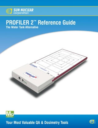
  • 1. PROFILER 2™ Reference Guide The Water Tank Alternative s u Your Most Valuable QA & Dosimetry Tools n
  • 2. Reference Guide, PROFILER 2™ © Copyright 2005-2008 by Sun Nuclear Corporation. All rights reserved. The information contained in this technical manual and the accompanying software program is protected by copyright and all rights are reserved by Sun Nuclear Corporation. Copying, duplicat- ing, selling, or otherwise distributing any part of this product without the prior written consent of Sun Nuclear Corporation is prohibited. Sun Nuclear Corporation reserves the right to make periodic modifications of this product without obligation to notify any person or entity of such revision. This guide is written for: PC software: version 1.3 Firmware: version 1.2.4 PROFILER 2™, Profiler™, IC PROFILER™, SRS PROFILER™, Daily QA3™, and ATLAS QA™ are trademarks of Sun Nuclear Corporation. Other trademarks or trade names are the property of their respective owners. Any changes or modifications not expressly approved by Sun Nuclear Corporation could void the user's authority to operate this equipment. Document 1174011, Rev F, 22 August 2008 Sun Nuclear Corporation 425A Pineda Court Melbourne, Florida 32940-7508 telephone + 1 321-259-6862 fax +1 321-259-7979 e-mail: contactus@sunnuclear.com http://www.sunnuclear.com Sun Nuclear Corporation is an ISO 13485:2003 registered company EMERGO EUROPE Molenstraat 15 2513 BH, The Hague The Netherlands Phone: +31.70.345.8570 Fax: +31.70.346.7299 ii
  • 3. Preface This section provides information about the latest PROFILER 2 firmware version (1.2.4), lists the new features in PROFILER 2 software version 1.3, describes the conventions used in the PRO- FILER 2 documentation, and lists safety instructions for using the PROFILER 2. Firmware Version 1.2.4 Firmware version 1.2.4 or higher must be installed on the PROFILER 2 for proper operation with software release 1.3. If firmware version 1.2.4 or higher is not installed on the device, the user is prompted that a firmware update is required to save array calibrations or dose calibrations to flash memory. Firmware version 1.2.4 also allows the software to automatically read device information (such as hardware version, product ID, and serial number) without accessing the device memory directly. The latest PROFILER 2 firmware can be downloaded from the Sun Nuclear Corporation web site, www.sunnuclear.com. See “Installing Firmware” on page 19 for installation instructions. Software Version 1.3 Note: For software version 1.3 to operate properly, new firmware must be installed. See “Firmware Version 1.2.4” . Version 1.3 of PROFILER 2 software adds the following new features: Data Plot View The View panel has a new tab, Data Plot. The Data Plot view provides a visual display of beam analysis parameters over the duration of the measurement. It can be used with saved files or real- time. The plottable options are flatness, beam center, field size, point symmetry, dose per Pulse, pulses/sec, dose rate, reference value, sensor voltage (or distance), and TPR (dose at depth). The Data Plot view is only for multi-frame files, Import Water Tank Measured Files Water tank data can now be imported into the software. The imported data can be displayed, com- pared, and manipulated using any of the PROFILER 2 tools. The supported import filters include Pinnacle (Philips), Mephysto (PTW), and OmniPro (Welhoffer). Smoothing The Control > Smooth Data menu option invokes a gaussian smoothing algorithm which is applied to the data before display/analysis. The extent of the smoothing is selected in the ‘Setup Parameters’ dialog box. This option is disabled by default. Analysis Panel Changes • The analysis panel now provides a horns parameter for photon beams and 90% electron posi- tion parameter for electron beams. The horns parameter shows the percent difference between the left horn and CAX in one panel, and the percent difference between the right horn and CAX in another panel. The 90% electron parameter display shows the outermost position on the left and right of the value which is 90% of the maximum found within the profile. • The Varian acceptance formula for flatness has been added to the flatness options. Preface iii
  • 4. Beam Edge Interpolation The default beam edge interpolation method has been improved. This arctangent method is more accurate than the previous linear penumbra interpolation method. The user can still select the lin- ear method in the Setup Parameters, if desired. Invert X and Y-Axes When ‘Invert’ is selected, the X-axis and Y-axis profiles of the selected file are inverted 180 degrees horizontally on the graph. In previous software releases only the Y profile was inverted. Top Plate Field Size Compensation A new option in the Configure Analysis dialog box allows the software to factor in the inherent buildup of the attached device when reporting the measured field size for calculating light/radia- tion field coincidence. If enabled, the software reports the field size at the detector plane; otherwise, it reports the field size at the overlay. Prompt to Resave if Files are Changed The software automatically detects if changes have been made to a file header, array calibration, or dose calibration, and when the user closes the window it prompts the user to “re-save”. Automatically Find Device When the software is launched it automatically searches all ports for an attached device. Zoom Options • A button has been added to the Data toolbar that allows the user to normalize all displayed graphs to physical center and zoom to the 85-110% view. • A new option in the ‘Setup Parameters’ dialog box allows the user to select if zoom will be permitted along the vertical and horizontal scales, or if only the vertical axis should be zoomed and the horizontal axis should remain fixed at the length of the array. File Name Suggestioning When saving data, the software will automatically suggest a file name based on the current date. The user can modify the file name, if desired. Set Energy Quicklist A ‘set energy’ option has been added to the Setup menu. The user can select an energy from the quick list, or choose the option to enter a custom value. The energy can also be selected using the Analysis panel context (right-click) menu. Array Calibration Improvements • The Array Calibration ‘Results’ window now displays a legend to identify the profile for each step of the calibration. • The on-screen array calibration instructions have been modified for clarity. • When calculating calibrated detectors by Field Size, the Array Calibration window displays the selected region with a blue box over the graphical template. • Array calibration files can be saved in a format that is compatible with older versions of ATLAS QA software. Default Mode and Data Type If the first file opened is a single file (*.prs) and it contains a dose calibration factor, the data type will default to Dose; otherwise the default data type is Normalized. If the first file opened is a multi- frame file (*.prm), the mode will default to Inst. Rate; otherwise the default mode is Total Dose. Orientation Offsets when Exporting in SNC ASCII When exporting data in SNC ASCII format, the export dialog now includes an option to apply ori- entation offsets to the data. If this option is selected, the orientation offsets specified in the file header are applied to the detector positions before the data is exported. iv Preface
  • 5. User Definable Background Collection Time The background collection time is now user-configurable. The range is from 10 to 600 seconds, and the default is 20 seconds. User Definable Collection Interval The sampling time (time between updates) can now be defined in the Setup Parameters dialog box. There are separate settings for continuous radiation and pulsed radiation. On-Graph Display Toolbar • An On-Graph Display toolbar has been added to the left side of the view panel. This toolbar contains buttons with graphical representations of the axes display options, such as all four axes, primary axes only, diagonal profiles only, or an individual axis. • The On-Graph Display toolbar to the left of the view panel also provides a new drop down menu to select the type of analysis parameter that will be displayed in the Graph view and Data view. The options are: None, Beam Center, Point Values, CAX Point Difference, Local Point Difference, Point Ratio, Varian Point Difference, Area Average, and Area. The options in bold type are new in this software release. • The On-Graph Display toolbar has a Project to 100cm checkbox which adjusts all loaded pro- files to 100 SSD before analysis and display. Conventions Button Name or Entry Bold typeface indicates the following: • A button name (i.e.,”…click the Edit button”), OR • An entry that the user must type (i.e., “Enter the username ADMIN...”), OR • An item for which an entry must be selected and the entry itself (i.e., “...select Photon from the Type list box...” Manual Titles Italicized typeface indicates the title of a manual (i.e., “See the Reference Guide or Online Help...”). Menu Options Bold italicized typeface indicates a menu option (i.e., “...select Setup > Preferences from the menu”). User Messages/Cross References Text within double quotes indicates the following: • A message displayed to the user (i.e., “...the message “Your devices are ready to use” is dis- played in the taskbar.”), OR • A cross referenced subsection in this manual (i.e., “...see “Measurement Buttons” on page...” Window/Dialog Box Names Text within single quotes indicates a window or dialog box name (i.e., “...the ‘Program Prefer- ences’ dialog box is displayed.” Symbols The following symbols are used in this document and in Sun Nuclear Corporation’s product labels. ! WARNING: Possible impact to personal safety. Preface v
  • 6. ! CAUTION: Important notation. Note: Important or supporting information. Go To: Provides guidance for which procedure to perform next. Manufacturer’s Identification (name and address). Date of Manufacture. Serial Number. Catalog Number. Consult instructions for use. Authorized representative in the European Community. Operating Information • Read the entire manual before using the product. • Use the product only within normal laboratory conditions maintained for human comfort: 18 to 30° C (64 to 86° F), 20 to 80% relative humidity. • This unit is not to be used as a standard during the calibration of a radiation source. However, the device can be calibrated to read absolute dose using data from a known source. • If the device cannot be calibrated to match the readings of a known standard, return it to the manufacturer for repair. • In this manual, CAUTIONS are used to indicate the possibility of damage to equipment. • Inspect cables periodically for damage. Return damaged cables to Sun Nuclear Corporation for repair or replacement if any mechanical or electrical degradation is suspected. vi Preface
  • 7. Safety Instructions Read and follow the following common-sense safety instructions: • Do not use the equipment with any power that does not match the power ratings listed on the power supply. • Do not permit water or any other liquids to spill onto or into the instrument or associated equipment. • Do not permit any short circuit of AC power that may be hazardous to users. • Do not use any power cord or power supply that is damaged or has broken insulation. Replace them immediately. • To protect insulation, never pull on the cable to disconnect the power cord from a wall socket; always grasp the plug. • Do not open or disassemble any device. Access to the inside of the device is for trained per- sonnel only. There are no user-repairable parts inside. Return all devices to the factory for repair. • When connected to AC power, position the device so that the plug is easily disconnected and is not obstructed. Warnings and Cautions CAUTION: Any changes or modifications not expressly approved by Sun Nuclear Cor- ! poration could void the user’s authority to operate this equipment. Preface vii
  • 8. This page is intentionally left blank. viii Preface
  • 9. Contents Preface . . . . . . . . . . . . . . . . . . . . . . . . . . . . . . iii Setting Up the USB Port . . . . . . . . . . . . . . . . . . . . 15 Firmware Version 1.2.4 . . . . . . . . . . . . . . . . . . . . . . iii USB Drivers for Windows Vista . . . . . . . . . . . . 15 Software Version 1.3 . . . . . . . . . . . . . . . . . . . . . . . . iii USB Drivers for Windows XP and 2000 . . . . . . 18 Data Plot View . . . . . . . . . . . . . . . . . . . . . . . . . . iii Verifying Installation of USB Drivers. . . . . . . . . 19 Import Water Tank Measured Files . . . . . . . . . . iii Removing the USB Drivers . . . . . . . . . . . . . . . . 19 Smoothing . . . . . . . . . . . . . . . . . . . . . . . . . . . . . iii Installing Firmware . . . . . . . . . . . . . . . . . . . . . . . . 19 Analysis Panel Changes . . . . . . . . . . . . . . . . . . . iii Setting up the Serial Port. . . . . . . . . . . . . . . . . . . . 20 Beam Edge Interpolation . . . . . . . . . . . . . . . . . . iv Launching the Software and Connecting . . . . . . . 20 Invert X and Y-Axes. . . . . . . . . . . . . . . . . . . . . . . iv Launching Software . . . . . . . . . . . . . . . . . . . . . 20 Top Plate Field Size Compensation . . . . . . . . . . iv Finding the Port . . . . . . . . . . . . . . . . . . . . . . . . 20 Prompt to Resave if Files are Changed . . . . . . . iv Find Device . . . . . . . . . . . . . . . . . . . . . . . . . 20 Automatically Find Device . . . . . . . . . . . . . . . . . iv To Select a Specific Port . . . . . . . . . . . . . . . 20 Zoom Options. . . . . . . . . . . . . . . . . . . . . . . . . . . iv Connecting Multiple Instruments . . . . . . . . . . . . . 21 File Name Suggestioning . . . . . . . . . . . . . . . . . . iv Shutdown. . . . . . . . . . . . . . . . . . . . . . . . . . . . . . . . 21 Set Energy Quicklist . . . . . . . . . . . . . . . . . . . . . . iv Removing PROFILER 2 Software . . . . . . . . . . . . . 21 Array Calibration Improvements. . . . . . . . . . . . . iv Software Removal (Windows Vista) . . . . . . . . . 21 Default Mode and Data Type . . . . . . . . . . . . . . . iv Software Removal (Windows XP) . . . . . . . . . . . 21 Orientation Offsets when Exporting in SNC ASCII Section 3. About PROFILER 2 Software . . . . 23 iv Graphical User Interface . . . . . . . . . . . . . . . . . . . . 23 User Definable Background Collection Time . . . v Menu Options . . . . . . . . . . . . . . . . . . . . . . . . . . . . 24 User Definable Collection Interval . . . . . . . . . . . v File Menu Options . . . . . . . . . . . . . . . . . . . . . . . . . 26 On-Graph Display Toolbar . . . . . . . . . . . . . . . . . v Import > Planned Dose . . . . . . . . . . . . . . . . . . 26 Conventions. . . . . . . . . . . . . . . . . . . . . . . . . . . . . . . v Options > Dose Map Orientation . . . . . . . . 27 Button Name or Entry. . . . . . . . . . . . . . . . . . . . . v File > Import >Watertank Measured. . . . . . . . 28 Manual Titles . . . . . . . . . . . . . . . . . . . . . . . . . . . v Select a Profile to Display Dialog Box . . . . . 28 Menu Options. . . . . . . . . . . . . . . . . . . . . . . . . . . v PT Data Offsets Dialog Box . . . . . . . . . . . . . 29 User Messages/Cross References. . . . . . . . . . . v File > Export > SNC ASCII . . . . . . . . . . . . . . . . 29 Window/Dialog Box Names . . . . . . . . . . . . . . . . v File > Export> DQA Measurement . . . . . . . . . 30 Symbols. . . . . . . . . . . . . . . . . . . . . . . . . . . . . . . . . . v File > Export > ADAC ASCII. . . . . . . . . . . . . . . 31 Operating Information . . . . . . . . . . . . . . . . . . . . . . . vi Edit > Edit Header . . . . . . . . . . . . . . . . . . . . . . 32 Safety Instructions . . . . . . . . . . . . . . . . . . . . . . . . vii Editing the File Header. . . . . . . . . . . . . . . . . 35 Warnings and Cautions . . . . . . . . . . . . . . . . . . . . . vii Using Default Header Entries . . . . . . . . . . . 35 Section 1. About the Instrument. . . . . . . . . . . 1 Tools > Collect Background. . . . . . . . . . . . . . . 35 Intended Use . . . . . . . . . . . . . . . . . . . . . . . . . . . . . . 1 Tools > Calibrate Array. . . . . . . . . . . . . . . . . . . 36 Description . . . . . . . . . . . . . . . . . . . . . . . . . . . . . . . 1 Edit SSD and Field Size . . . . . . . . . . . . . . . . 37 Features. . . . . . . . . . . . . . . . . . . . . . . . . . . . . . . . . . 2 Array Calibration Dialog Box (During Applications. . . . . . . . . . . . . . . . . . . . . . . . . . . . . . . 2 Calibration) . . . . . . . . . . . . . . . . . . . . . . . . . . 38 More Applications . . . . . . . . . . . . . . . . . . . . . . . 2 Tools > Calibrate Dose. . . . . . . . . . . . . . . . . . . 39 Parts and Accessories. . . . . . . . . . . . . . . . . . . . . . . 3 Tools > Download Code . . . . . . . . . . . . . . . . . 40 Setup Overview . . . . . . . . . . . . . . . . . . . . . . . . . . . . 4 Tools > Save Calibration to Flash. . . . . . . . . . . 40 Construction . . . . . . . . . . . . . . . . . . . . . . . . . . . . . . 5 Tools > Concatenate . . . . . . . . . . . . . . . . . . . . 41 Precision Template. . . . . . . . . . . . . . . . . . . . . . . 6 Setup > Parameters . . . . . . . . . . . . . . . . . . . . . 42 End Panel. . . . . . . . . . . . . . . . . . . . . . . . . . . . . . . . . 7 Setup > Analysis . . . . . . . . . . . . . . . . . . . . . . . 43 Power/Data Interface (P/DI). . . . . . . . . . . . . . . . . . . 7 Setup > Set Energy . . . . . . . . . . . . . . . . . . . . . 46 Cables . . . . . . . . . . . . . . . . . . . . . . . . . . . . . . . . . . . 8 Setup > View Calibration . . . . . . . . . . . . . . . . . 46 Finding Additional Information . . . . . . . . . . . . . . . . 8 Setup > Electron Wedge Calibration . . . . . . . . 47 Using Online Help. . . . . . . . . . . . . . . . . . . . . . . . 8 Setup > Wedge Configuration . . . . . . . . . . . . . 48 Specifications . . . . . . . . . . . . . . . . . . . . . . . . . . . . . 9 Setup > Serial Port . . . . . . . . . . . . . . . . . . . . . . 49 Help > About . . . . . . . . . . . . . . . . . . . . . . . . . . 49 Section 2. Software Setup . . . . . . . . . . . . . . 13 Context Menus . . . . . . . . . . . . . . . . . . . . . . . . . . . 50 Overview . . . . . . . . . . . . . . . . . . . . . . . . . . . . . . . . 13 Toolbar Area. . . . . . . . . . . . . . . . . . . . . . . . . . . . . . 51 Single Installation . . . . . . . . . . . . . . . . . . . . . . . . . 13 Acquisition Toolbar . . . . . . . . . . . . . . . . . . . . . . 51 Multiple Installations . . . . . . . . . . . . . . . . . . . . . . . 13 Display Toolbar . . . . . . . . . . . . . . . . . . . . . . . . . 52 USB Connection . . . . . . . . . . . . . . . . . . . . . . . . . . 14 Dose Calibration Toolbar . . . . . . . . . . . . . . . . . 52 Serial Connection . . . . . . . . . . . . . . . . . . . . . . . . . 14 Array Calibration Toolbar . . . . . . . . . . . . . . . . . 52 Serial Connection with P/DI . . . . . . . . . . . . . 14 Data Toolbar . . . . . . . . . . . . . . . . . . . . . . . . . . . 53 Serial Port Alternatives . . . . . . . . . . . . . . . . 15 Contents ix
  • 10. Status Toolbar . . . . . . . . . . . . . . . . . . . . . . . . . 53 Viewing a Saved Calibration File. . . . . . . . . . . . 92 Movie Player Toolbar . . . . . . . . . . . . . . . . . . . . 54 Calculating Calibrated Detectors for Small Fields On Graph Display Toolbar . . . . . . . . . . . . . . . . 54 93 Legend Panel. . . . . . . . . . . . . . . . . . . . . . . . . . . . . 55 Selecting Calibrated Detectors By Field Size . . 93 Legend Panel Details . . . . . . . . . . . . . . . . . . . . 55 Selecting Calibrated Detectors By Profile Shape . View Panel . . . . . . . . . . . . . . . . . . . . . . . . . . . . . . . 57 93 Graph View . . . . . . . . . . . . . . . . . . . . . . . . . . . . . . 58 Dose Calibration . . . . . . . . . . . . . . . . . . . . . . . . . . 94 Graph View Details . . . . . . . . . . . . . . . . . . . . . . 58 Adding a Dose Measurement. . . . . . . . . . . . . . 94 Data Points . . . . . . . . . . . . . . . . . . . . . . . . . . . . 59 Saving a Dose Calibration To Flash . . . . . . . . . 96 Graph Scale . . . . . . . . . . . . . . . . . . . . . . . . . . . 59 Changing the Dose Calibration Factor . . . . . . . 96 Zoom. . . . . . . . . . . . . . . . . . . . . . . . . . . . . . . . . 59 Setting Up A Default Dose Calibration . . . . . . . 96 Hiding a Profile . . . . . . . . . . . . . . . . . . . . . . . . . 60 Removing A Dose Calibration Value . . . . . . . . . 96 Normalizing the Graph . . . . . . . . . . . . . . . . . . . 61 Subtract Background . . . . . . . . . . . . . . . . . . . . 97 If Normalization Settings Do Not Match Data Recalibration Interval . . . . . . . . . . . . . . . . . . . . . . . 97 Type . . . . . . . . . . . . . . . . . . . . . . . . . . . . . . . 61 Section 5. Measuring Radiation . . . . . . . . . . 99 On Graph Symmetry. . . . . . . . . . . . . . . . . . . . . 61 Positioning PROFILER 2 . . . . . . . . . . . . . . . . . . . . 99 Graph View Context Menu . . . . . . . . . . . . . . . . 62 Loading Calibration References . . . . . . . . . . . . . . 99 Header View . . . . . . . . . . . . . . . . . . . . . . . . . . . . . 62 Array Calibration File . . . . . . . . . . . . . . . . . . . . . 99 Copy and Paste Header Fields . . . . . . . . . . . . . 63 Dose Calibration Value . . . . . . . . . . . . . . . . . . 100 Header View Context Menu . . . . . . . . . . . . . . . 63 Inherent Buildup and Physical Depth . . . . . . . . . 101 Data View . . . . . . . . . . . . . . . . . . . . . . . . . . . . . . . 64 Measuring A Single Profile . . . . . . . . . . . . . . . . . 101 Beam Tuning View . . . . . . . . . . . . . . . . . . . . . . . . 66 Starting the Profile Measurement . . . . . . . . . 101 Data Plot View . . . . . . . . . . . . . . . . . . . . . . . . . . . . 68 Checking the Gain. . . . . . . . . . . . . . . . . . . . . . 101 Plot Settings Details . . . . . . . . . . . . . . . . . . . . . 69 Saving the Profile . . . . . . . . . . . . . . . . . . . . . . 102 Analysis Panel . . . . . . . . . . . . . . . . . . . . . . . . . . . . 70 Multiple Frame Capture . . . . . . . . . . . . . . . . . . . . 103 Analysis Panel Details . . . . . . . . . . . . . . . . . . . 70 Collecting Multiple Frame Data . . . . . . . . . . . 103 Changing the Analysis Panel Elements . . . . . . 72 Concatenating Two Measurements . . . . . . . . . . 103 Editing the Analysis Panel Parameters. . . . . . . 73 Concatenation Procedure . . . . . . . . . . . . . . . . 104 Edit Field Parameters . . . . . . . . . . . . . . . . . 73 Continuous Radiation . . . . . . . . . . . . . . . . . . . . . 106 Edit Penumbra Parameters . . . . . . . . . . . . . 74 Checking Electron Energy With a Wedge . . . . . . 106 Edit Light Field and SSD Parameters . . . . . 74 Electron Energy Wedge Setup . . . . . . . . . . . . 106 Edit Flatness Parameters. . . . . . . . . . . . . . . 74 Electron Energy Wedge Calibration . . . . . . . . 106 Edit Symmetry Parameters . . . . . . . . . . . . . 75 Collect Data . . . . . . . . . . . . . . . . . . . . . . . . 106 Edit Energy Analysis Parameters. . . . . . . . . 75 Load Electron Energy Files . . . . . . . . . . . . 107 Edit Wedge Parameters. . . . . . . . . . . . . . . . 76 To Add a New Calibration Set . . . . . . . . . . 107 Edit Configuration Parameters . . . . . . . . . . 76 Apply Calibration . . . . . . . . . . . . . . . . . . . . 108 Setting the Machine Energy in the Header . . . 77 Taking a Measurement . . . . . . . . . . . . . . . . . . 108 Changing the Analysis Panel Position . . . . . . . 78 Photon Wedge Measurements . . . . . . . . . . . . . . 109 Hiding Items . . . . . . . . . . . . . . . . . . . . . . . . . . . 78 Beam Tuning . . . . . . . . . . . . . . . . . . . . . . . . . . . . 110 Drag and Drop Positioning . . . . . . . . . . . . . . . . . . 78 Overview . . . . . . . . . . . . . . . . . . . . . . . . . . . . . 110 Section 4. Calibrating the System. . . . . . . . . 81 Using the Beam Tuning Display . . . . . . . . . . . 110 Array Calibration . . . . . . . . . . . . . . . . . . . . . . . . . . 81 Data Analysis Using the Data Plot. . . . . . . . . . . . 111 Array Calibration Fixture . . . . . . . . . . . . . . . . . . 81 Overview . . . . . . . . . . . . . . . . . . . . . . . . . . . . . 111 Background Measurements . . . . . . . . . . . . . . . 82 Using the Data Plot Display . . . . . . . . . . . . . . 111 Automatic Background . . . . . . . . . . . . . . . . 82 Data Interpretation. . . . . . . . . . . . . . . . . . . . . . . . 112 Manual Background. . . . . . . . . . . . . . . . . . . 82 Section 6. Viewing Files and Printing . . . . . 113 Array Calibration Conditions. . . . . . . . . . . . . . . 82 Opening and Saving Files . . . . . . . . . . . . . . . . . . 113 Array Calibration Procedure . . . . . . . . . . . . . . . . . 83 Selecting File Type . . . . . . . . . . . . . . . . . . . . . 113 Calibration Setup . . . . . . . . . . . . . . . . . . . . . . . 83 Saving Measured Data . . . . . . . . . . . . . . . . . . 114 Calibration Steps . . . . . . . . . . . . . . . . . . . . . . . 84 Duplicating a File . . . . . . . . . . . . . . . . . . . . . . 114 Overview . . . . . . . . . . . . . . . . . . . . . . . . . . . 84 Re-Opening a File . . . . . . . . . . . . . . . . . . . . . . 114 Step A . . . . . . . . . . . . . . . . . . . . . . . . . . . . . 84 Closing a File. . . . . . . . . . . . . . . . . . . . . . . . . . 114 Step B . . . . . . . . . . . . . . . . . . . . . . . . . . . . . 85 Clearing a File . . . . . . . . . . . . . . . . . . . . . . . . . 114 Step C . . . . . . . . . . . . . . . . . . . . . . . . . . . . . 86 Hiding a File . . . . . . . . . . . . . . . . . . . . . . . . . . 114 Step D . . . . . . . . . . . . . . . . . . . . . . . . . . . . . 87 Changing Colors . . . . . . . . . . . . . . . . . . . . . . . . . 114 Viewing the Array Calibration Results . . . . . . . 88 Comparing Profiles . . . . . . . . . . . . . . . . . . . . . . . 115 Saving the Array Calibration File. . . . . . . . . . . . 89 Movie Playback . . . . . . . . . . . . . . . . . . . . . . . . . . 116 Saving Array Calibration to Flash Memory . . . . 89 Reports . . . . . . . . . . . . . . . . . . . . . . . . . . . . . . . . 117 Calibration with Saved Files . . . . . . . . . . . . . . . 90 Print Options . . . . . . . . . . . . . . . . . . . . . . . . . . 117 Loading a Saved Calibration File . . . . . . . . . . . 91 Printing Reports . . . . . . . . . . . . . . . . . . . . . . . 119 x Contents
  • 11. Printing Screens . . . . . . . . . . . . . . . . . . . . . . . 119 Import Filter Updates . . . . . . . . . . . . . . . . . . . 150 Importing Water Tank Measured Files . . . . . . . . 150 Section 7. Importing/Exporting Data. . . . . . 121 Water Tank File Import Procedure . . . . . . . . . 151 Importing Planned Dose Files . . . . . . . . . . . . . . . 121 Exporting Data . . . . . . . . . . . . . . . . . . . . . . . . . . . 152 Import Filter . . . . . . . . . . . . . . . . . . . . . . . . . . 121 SNC ASCII Export . . . . . . . . . . . . . . . . . . . . . . 153 TPS Dose Maps . . . . . . . . . . . . . . . . . . . . . . . 121 From Menu. . . . . . . . . . . . . . . . . . . . . . . . . 153 About Dose Maps . . . . . . . . . . . . . . . . . . . . . 121 By Copying . . . . . . . . . . . . . . . . . . . . . . . . . 153 Import Filter - Supported File Types. . . . . . . . 122 DQA3 Measurement Export . . . . . . . . . . . . . . 154 About EPIDose Files . . . . . . . . . . . . . . . . . 122 Pinnacle Export . . . . . . . . . . . . . . . . . . . . . . . . 154 About DICOM Files . . . . . . . . . . . . . . . . . . 122 Header fields . . . . . . . . . . . . . . . . . . . . . . . 154 PROFILER 2 Plan Grid Resolution . . . . . . . . . 122 Data Orientation . . . . . . . . . . . . . . . . . . . . . 155 Preparing Dose Maps for Import . . . . . . . . . . 123 Wedge and Circular Collimator . . . . . . . . . 155 Exporting 3D Line ERGO++ Files . . . . . . . . . 123 Export Procedure . . . . . . . . . . . . . . . . . . . . 155 Exporting AccuKnife AccuSoft XL Files . . . . . 124 Exporting Pinnacle3 (Philips) Files . . . . . . . . . 124 Section 8. Interpreting Measurements . . . . 157 Exporting BrainLAB Brain Scan Files . . . . . . . 127 Assuring Accurate Measurements . . . . . . . . . . . 157 Exporting CMS Files . . . . . . . . . . . . . . . . . . . . 127 Calibration . . . . . . . . . . . . . . . . . . . . . . . . . . . . 157 Focus and XIO files . . . . . . . . . . . . . . . . . . 127 Reporting Hardware or Software Faults . . . . . 157 Generate a General Dose Plan Export File 127 Calibration Concepts . . . . . . . . . . . . . . . . . . . . . . 157 Generate a Beam Map File Using the Decimal Array Calibration . . . . . . . . . . . . . . . . . . . . . . . 157 Utility . . . . . . . . . . . . . . . . . . . . . . . . . . . . . 128 Calibration Files. . . . . . . . . . . . . . . . . . . . . . . . 157 Exporting Elekta Precise Plan Files . . . . . . . . 129 Theory of Calibration Using Wide Fields . . . . 158 Exporting Memorial Sloan Kettering Cancer Care Profile Storage And Data Format. . . . . . . . . . . . . 159 Files . . . . . . . . . . . . . . . . . . . . . . . . . . . . . . 129 Saving a Profile . . . . . . . . . . . . . . . . . . . . . . . . 159 Exporting MDS Nordion Helax TMS Files . . . 130 PROFILER 2 File Formats . . . . . . . . . . . . . . . . 159 Overly Complex DICOM File Format . . . . . 130 SRS Profiler File Formats . . . . . . . . . . . . . . . . 159 Exporting NOMOS CORVUS Files . . . . . . . . . 131 Profiler 1 File Formats. . . . . . . . . . . . . . . . . . . 160 Exporting Nucletron Files . . . . . . . . . . . . . . . . 131 Analysis of a Profile . . . . . . . . . . . . . . . . . . . . . . . 160 Nucletron PLATO File . . . . . . . . . . . . . . . . 131 Field Size . . . . . . . . . . . . . . . . . . . . . . . . . . . . . 162 Nucletron Oncentra TP File . . . . . . . . . . . . 132 Beam Center . . . . . . . . . . . . . . . . . . . . . . . . . . 163 Exporting PerMedics Odyssey Files . . . . . . . 133 Light/Radiation Field Coincidence . . . . . . . . . 163 Exporting Prowess Panther Files . . . . . . . . . . 134 Penumbra . . . . . . . . . . . . . . . . . . . . . . . . . . . . 163 Exporting Radionics XKnife Files . . . . . . . . . . 134 Flatness. . . . . . . . . . . . . . . . . . . . . . . . . . . . . . 163 Exporting RAHD Alpha 3D Pro Files. . . . . . . . 136 Flatness Calculation by Variance . . . . . . . . 163 Exporting Siemens KonRad Files . . . . . . . . . . 136 Ratio (IEC) Flatness Calculation . . . . . . . . . 164 Exporting TGM ARTP (Topslane) Files . . . . . . 137 Varian Flatness Calculation . . . . . . . . . . . . 164 Exporting Varian Files . . . . . . . . . . . . . . . . . . . 137 Symmetry . . . . . . . . . . . . . . . . . . . . . . . . . . . . 164 CadPlan File . . . . . . . . . . . . . . . . . . . . . . . . 137 CAX Point Difference Symmetry . . . . . . . . 165 Eclipse File. . . . . . . . . . . . . . . . . . . . . . . . . 138 Local Point Difference Symmetry . . . . . . . 165 Exporting Files in DICOM File Format . . . . . . 138 Point Ratio (Ratio IEC) Symmetry . . . . . . . 165 DICOM CR image file . . . . . . . . . . . . . . . . 139 Varian Point Difference Symmetry. . . . . . . 166 Exporting Files in SunCOM File Format . . . . . 139 Area Average Symmetry . . . . . . . . . . . . . . 166 SunCOM File Specification. . . . . . . . . . . . . . . 139 Area Symmetry . . . . . . . . . . . . . . . . . . . . . 167 SunCOM Optional Header Information . . . 140 Horn Values . . . . . . . . . . . . . . . . . . . . . . . . . . . . . 167 SunCOM Required Keywords . . . . . . . . . . 140 90% Position . . . . . . . . . . . . . . . . . . . . . . . . . . . . 168 Example SunCOM File. . . . . . . . . . . . . . . . 141 Beam Interpolated Flatness and Symmetry . . . . 168 Using the PROFILER 2 Import Filter. . . . . . . . 141 Beam Edge Interpolation . . . . . . . . . . . . . . . . . . . 169 Aligning Plan Dose Maps to PROFILER 2 . . . 142 Smoothing . . . . . . . . . . . . . . . . . . . . . . . . . . . . . . 169 Beam Center Offset. . . . . . . . . . . . . . . . . . 143 Calculating Calibrated Detectors For Small Fields . . Rotation . . . . . . . . . . . . . . . . . . . . . . . . . . . 143 169 Measuring an Equivalent Profile. . . . . . . . . . . 144 Profile Comparison . . . . . . . . . . . . . . . . . . . . . . . 170 Import Window Display . . . . . . . . . . . . . . . . . 145 Percent Difference . . . . . . . . . . . . . . . . . . . . . 170 TPS Import Window Menu Options . . . . . 145 Compare Index . . . . . . . . . . . . . . . . . . . . . . . . 170 TPS Import Window Toolbar . . . . . . . . . . . 145 Data Type and Mode Selection . . . . . . . . . . . . . . 171 Inverting Imported Files . . . . . . . . . . . . . . . . . 146 Overview . . . . . . . . . . . . . . . . . . . . . . . . . . . . . 171 Check for Dose Map Inversion . . . . . . . . . 147 Normalized . . . . . . . . . . . . . . . . . . . . . . . . . 171 Excluding Import Filters . . . . . . . . . . . . . . . . . 148 Inst Rate and Avg Rate Modes. . . . . . . . . . . . 171 Importing a Slice Or Volume File . . . . . . . . . . 148 Concatenated And Double Profiles . . . . . . . . 172 TPS File Import - Troubleshooting . . . . . . . . . 149 Electron Energy Wedge Analysis . . . . . . . . . . . . 172 Opening Plan Files. . . . . . . . . . . . . . . . . . . 149 Electron Energy Calculated by Slope Analysis 172 Error Messages . . . . . . . . . . . . . . . . . . . . . 149 Contents xi
  • 12. Electron Energy Calculated by Intercept Analysis . Detector Layout and Geometry . . . . . . . . . . . 182 172 ATLAS QA Test Plan . . . . . . . . . . . . . . . . . . . . . . 182 Photon Energy Wedge Analysis . . . . . . . . . . . . . 173 Importing a PROFILER 2 Array Calibration File 183 Calculation 1 . . . . . . . . . . . . . . . . . . . . . . . . . . 173 Setting up the Scheme Tree . . . . . . . . . . . . . . 184 Calculation 2 . . . . . . . . . . . . . . . . . . . . . . . . . . 173 Setting Up the Template for Beam Tracking . 185 Calculation 3 . . . . . . . . . . . . . . . . . . . . . . . . . . 173 Calibrating the QA Template . . . . . . . . . . . . . 186 Real Time Studies During Accelerator Adjustment . . Measurement with ATLAS QA . . . . . . . . . . . . . . 187 174 Preparing for Measurement . . . . . . . . . . . . . . 187 Compare in Accelerator QA . . . . . . . . . . . . . . 174 Section 11. Maintaining Your System. . . . . 191 Fixed Wedge QA . . . . . . . . . . . . . . . . . . . . . . 175 Maintaining Hardware . . . . . . . . . . . . . . . . . . . . . 191 Moving (Dynamic, Virtual) Wedge QA . . . . . . 175 Parts and Repairs . . . . . . . . . . . . . . . . . . . . . . 191 About Profile Acquisition. . . . . . . . . . . . . . . . . . . 175 Storage . . . . . . . . . . . . . . . . . . . . . . . . . . . . . . 191 Radiation Measurement . . . . . . . . . . . . . . . . . 175 Cleaning . . . . . . . . . . . . . . . . . . . . . . . . . . . . . 191 Section 9. PROFILER 2 Accessories . . . . . . 177 Disposal and Recycling. . . . . . . . . . . . . . . . . . 191 Isocentric Mounting Fixture (IMF). . . . . . . . . . . . 177 Maintaining Software and Firmware . . . . . . . . . . 191 Purpose. . . . . . . . . . . . . . . . . . . . . . . . . . . . . . 177 Verify Software Version Number . . . . . . . . . . 191 Description . . . . . . . . . . . . . . . . . . . . . . . . . . . 177 Updating Software and Firmware. . . . . . . . . . 192 IMF Installation . . . . . . . . . . . . . . . . . . . . . . . . 178 Installing Firmware . . . . . . . . . . . . . . . . . . . . . 192 Varian . . . . . . . . . . . . . . . . . . . . . . . . . . . . . 178 Troubleshooting. . . . . . . . . . . . . . . . . . . . . . . . . . 193 Siemens . . . . . . . . . . . . . . . . . . . . . . . . . . . 178 LED Indications . . . . . . . . . . . . . . . . . . . . . . . . 193 Elekta . . . . . . . . . . . . . . . . . . . . . . . . . . . . . 179 PROFILER 2 Troubleshooting . . . . . . . . . . . . . 193 Operation . . . . . . . . . . . . . . . . . . . . . . . . . . . . 180 Minimizing Radiation Damage. . . . . . . . . . . . . . . 193 Contacting Client Solutions . . . . . . . . . . . . . . . . . 194 Section 10. Profiler 2 with ATLAS QA . . . . 181 About ATLAS QA . . . . . . . . . . . . . . . . . . . . . . . . . 181 Index . . . . . . . . . . . . . . . . . . . . . . . . . . 195 PROFILER 2 Display in ATLAS QA . . . . . . . . . . . 181 xii Contents
  • 13. 1 About the Instrument Intended Use The Model 1174 Profiler 2 has two intended uses. Its primary intended use is QA measurement and analysis of the radiation output profile across the beam of an ionizing radiation treatment machine (LINAC or Cobalt 60). Its secondary intended use is the measurement of beam data in radiotherapy departments for dose modeling in the treatment planning computer. ! WARNING: This product is intended to be used under the direction of a quali- fied medical physicist. Description PROFILER 2 measures the radiation intensity along X and Y axes in a beam of ionizing radiation. The instrument is used to test the output of a radiation therapy device such as a linear accelerator (linac). PROFILER 2 is ideal for machine quality assurance, including beam modeling, verification of dose, beam shape measurement, beam steering adjustments, light-field coincidence, electron energy, and measurement of 30 cm dynamic wedges. Figure 1-1. PROFILER 2 instrument for accelerator beam QA The PROFILER 2 has 139 solid-state detectors at 4 mm spacing situated along X and Y axes to allow simultaneous measurement in two perpendicular planes. The Y-array with 83 detectors, has a maximum field of 30 cm at 100 cm SSD. The X-array, with 57 detectors, has a maximum field size of 20 cm at 100 SSD. If necessary, larger field sizes are possible by taking concatenated mea- surements at 100 cm SDD, or by taking a single measurement at a shorter SSD. PROFILER 2 uses the same 25 meter cable as other Sun Nuclear products. The cable connects the PROFILER 2 to a small power supply located outside the linac bunker. A computer is required to communicate with the PROFILER 2 and display the data. Intended Use 1
  • 14. The PROFILER 2 software operates in Windows. Both rate and integrated profiles are measured and displayed. The rate profile is a real time update of the beam intensity; each update can be saved for later playback. There is no limit on the beam duration or integration. The data acquisition cycle may be set to be triggered by accelerator pulses such that data is transferred while the beam is off. Features • Simultaneous measurement on both X and Y axes • 4 mm detector spacing • Field sizes up to 20 x 30 cm • Measures each accelerator pulse (dose per pulse) • Trigger detectors that respond to the beam in microseconds • Frame capture (up to 14 frames per second) and play back • Measurement of dynamic wedges up to 30 cm • Real-time measurement - profile and analysis data displayed instantly • Beam tuning display shows dynamic changes in beam characteristics to see immediate results of adjustments to the linac • Data plot display provides a visual representation of the beam characteristics over time • Ability to save profiles to disk • On-screen comparison of saved profiles • Concatenation of two measurements to measure beams as wide as 60 cm • No limit on beam duration or integration • Import water tank measured files and TPS dose maps. • Export measurements to Pinnacle TPS. • Daily software trending using the ATLAS software (optional) • Optional Isocentric Mounting Fixture (IMF) places detectors at center of rotation and allows measurement at all gantry angles Applications Typical uses of the PROFILER 2 may include the following: • Commissioning—Before a TPS can be used to treat a patient, a series of tests must be per- formed to establish the dosimetric properties of the accelerator that the TPS will use to deliver its plan. PROFILER 2 accurately measures dosimetric information that can be exported to a Pinnacle TPS. • Periodic QA measurements—weekly, quarterly, or annual measurements can provide assur- ance that the beam and the MLC are functioning properly. Saved standard measurements can be compared to the periodic measurements to verify the exposure is the same. • IMRT validation—Treatment planning files can be imported and their profiles can be directly compared to the corresponding measured profiles. • Machine adjustment—The PROFILER 2 can be used to verify that adjustments to the equip- ment result in the desired beam shape, alignment, and dose. The machine can be checked and adjusted for flatness, symmetry, penumbra, light-radiation coincidence, and field size on either axis. The 4 mm spacing of PROFILER 2’s detectors lets you see flatness anomalies along the beam. In Beam Tuning view, the results of the adjustment are immediately dis- played, and you can quickly adjust the machine to specifications. More Applications In addition to simple profile measurements, you can use PROFILER 2 for additional applications: • Concatenated measurement—Profiles of large beams, up to 60 x 20 cm, can be graphed by making two separate measurements and concatenating the resulting data, creating a single graph. Using a PROFILER 2, offset the array to capture one half of the beam. Center the cross 2 Section 1. About the Instrument
  • 15. hairs on an offset detector location, selected as the pivot point. Then make an exposure. When the data is received, select Concatenate from the menu, rotate the PROFILER 2 180 degrees around the selected offset pivot point, and make a second exposure. The second measurement is concatenated to the first by the software, and the two measurements are displayed as a single graph. • Multiple frame capture—Multiple frame capture is like a taking a “movie.” You collect a regular sequence of profiles over time. • The playback options let you play back the collected profiles at variable speeds, using the frame capture playback bar in the software. • Multiple frame capture lets you study the characteristics of transient events during warm-up, which may be important in IMRT applications. • Continuous radiation—PROFILER 2 measures continuous radiation beams as well as pulsed accelerator beams. This allows you to check machines such as cobalt-60 and certain X-ray sources. • Electron energy verification wedge—The electron energy verification wedge lets you verify electron energy with a wedge phantom. After calibration and exposure, the PC software cal- culates electron energy by slope or intercept analysis. • Photon wedge analysis—Dynamic and virtual wedge routines can be viewed during and after the wedge is formed. The measurement can be viewed, stored, and compared. • Beam data export—Beam data can be exported to a Pinnacle Treatment Planning Computer (TPC) for beam modelling. Parts and Accessories After unpacking, identify the following parts and accessories: 14 15 1 2 3 4 11 10 11 9 8 7 6 5 No. Part Number Qty Description 1 1174300 1 PROFILER 2 assembly 2 741008 1 Power converter, switching, 110-240 VAC, 1-phase, 50-60 Hz to 18 VDC 3 801008 1 Line power cord, IEC Plug to USA style 4 022230 1 Power/Data Interface (P/DI) Figure 1-2. Parts available with the PROFILER 2 Parts and Accessories 3
  • 16. No. Part Number Qty Description 5 801038 1 Power/serial data cable, 8-pin DIN, 25 m 6 801037 1 Power/serial data test cable, 8-pin DIN, 1.2 m 7 801032 1 Serial cable, 9-pin D type, 2 m 8 801041 1 USB cable, 2 m 9 1174030 1 Software CD (including PDF copies of documentation) 10 1174350 1 Calibration fixture, clear Lucite 11 1174354 2 Extension rail, calibration fixture 12 1174012 1 Getting Started guide (not shown) 13 117081 - Electron energy verification wedge, aluminum (optional) (not shown) 14 1174101 1 Build-up plate, Virtual Water, 1 x 30 x 35 cm 15 1174102 1 Build-up plate, Virtual Water, 2 x 30 x 35 cm 16 1174103 - Build-up plate, Virtual Water, 5 cm thick (optional) (not shown) 17 1175000-1 - Isocentric mounting fixture (specify linac manufacturer when ordering) (optional) (not shown) 18 1174000-5 - Case, carrying (optional) (not shown) Figure 1-2. Parts available with the PROFILER 2 The optional buildup plates (numbers 14 & 15 in the above table) may be required if you calibrate at higher energies. Setup Overview The PROFILER 2 is quick and easy to use. To make a beam measurement, place the PROFILER 2 instrument on the treatment table and connect it to the computer. Then expose it to the beam. As PROFILER 2 is exposed to radiation, the software instantly displays the acquired dose on the monitor. • In the treatment room, place the PROFILER 2 on the couch aligned to the lasers and directly under the accelerator beam. CAUTION: To prevent damage to the electronics, do not directly irradiate the electron- ! ics section (raised area) of the instrument. • Connect the instrument to the P/DI unit in the control room with the 25-meter power/data cable (threaded permanently through the cable tray or temporarily under the door). • In the control room, install the PROFILER 2 software on a Windows computer. • Connect the P/DI power supply to the power outlet and then to the P/DI unit. • Connect the P/DI to the computer using a USB or serial cable. See “USB Connection” on page 14 or “Serial Connection” on page 14. • Launch the software and initiate communication with the instrument. See “Launching the Software and Connecting” on page 20. • Perform array and dose calibrations (if not already done). See “Calibrating the System” on page 81. • Collect a measurement. See “Measuring Radiation” on page 99. As dose is being delivered, radiation profiles are displayed graphically and numerically. • Review results, analyze measurements, compare exposures, and save files for later use. 4 Section 1. About the Instrument
  • 17. Control Room Treatment Room Figure 1-3. Using PROFILER 2 Construction The instrument consists of a single flat housing with the detector arrays at one end and the elec- tronics section at the other end. • Array Section—The array section shows the location of the detectors mounted on the under- lying circuit board as well as field size marks for proper alignment. The array detectors, shown by small black dots, are spaced 4 mm apart. A precision alignment template is attached to the top of the array section. • Electronics Section—The analog and digital electronics are located inside the raised cover at one end of the instrument, below the line indicated with the text “KEEP THE DIRECT BEAM ABOVE THIS LINE. EXPOSURE MAY VOID WARRANTY.” The electronic components can be damaged by radiation if exposed to the direct beam.1 CAUTION: Keep the electronics section out of the direct beam. Do not allow the direct ! beam to fall outside of the detector area or you could damage the instrument. Pro- longed exposure of the electronics to direct radiation could void your warranty! 1. This device contains optichromic radiation dosimeters in the electronics area. To maintain warranty, direct irradiation to the electronics must be avoided. The dosimeters will be read if this device is returned for service. An indication of direct irradiation to the electronics will VOID the warranty. Construction 5
  • 18. Precision Template The PROFILER 2 precision alignment template is shown below. Last detector in Y-axis array (83) Alignment grid Common center detector (Y=42, X=29) First detector in X-axis array (01) Last detector in X-axis array (57) Array section Build-up alignment hole First detector in Y-axis array (01) Bubble level Electronics section Figure 1-4. Detector Locations and Geometry • Alignment grid—The black rectangular alignment grids are for aligning the PROFILER 2 with the cross hairs and light field of the accelerator. Grids are provided for 10 x 10, 15 x 15, 20 x 20, and 20 x 30 cm. • Detector location marks—The small black dots show the physical location of the detectors in the X-Y plane. Each dot has a number which corresponds to the detector number in the display. • Alignment holes—There are two alignment holes in the bottom portion of the white area which provide key alignment for build-up plates. The build-up plates have matching pegs that fit into the holes. • Bubble level—A bubble level, mounted in the top surface, is used with the leveling feet on the bottom of the PROFILER 2 to adjust the array perpendicular to the beam axis. 6 Section 1. About the Instrument
  • 19. End Panel The PROFILER 2 end panel has the following connectors and LEDs: Figure 1-5. End Panel Connections and Indicators • REF—Reference detector for future application. • PWR/DATA—Power input from the PROFILER 2 power supply and input/output of serial data. • A, B, C, D—LED status lights for troubleshooting by Sun Nuclear technicians. See “Trouble- shooting” on page 193. Power/Data Interface (P/DI) The P/DI (Figure 1-6) routes power to the instrument and translates communications between the instrument and a personal computer. An external power converter automatically adapts to any power source within the range of 100-240 VAC, 1 phase, 47-63 Hz. With the P/DI, two types of computer connection are possible: USB (Universal Serial Bus) and serial. Each type of connection takes a different cable. Both types of cables are shipped with PRO- FILER 2. Figure 1-6. Power/Data Interface (P/DI) End Panel 7
  • 20. Cables The following cables are supplied: • Power cord—a standard 3-wire, grounded power cord; connects to wall socket. • Power/Data cable—25-meter round cable with two 8-pin DIN connectors. Connects the PRO- FILER 2 to the P/DI. The cable carries both power and data between the PROFILER 2 and the P/DI. The connector pins are 1:1 and may be connected to the PROFILER 2 and P/DI with either end. (A similar 1.2-meter cable is used as a test cable.) • Power converter—connects the power cord to the P/DI (power/data interface) located in the control room. Supplies 18 VDC to the P/DI. • USB cable—a standard Universal Serial Bus cable to connect the P/DI to your computer. • Serial cable—a standard PC serial cable (RS-232) with M/F, 9-pin D-connectors to connect the P/DI to your computer. Finding Additional Information The following information about PROFILER 2 is available: • Tool Tip Hints—If the cursor hovers over a button or a function tab, a message appears in an adjacent pop-up window. For example, if you hover the cursor over the controls on the toolbar, little windows appear that contain the name of the button or function. • Tip of the Day—The Tip of the Day box provides helpful tips and describes useful features to help you learn more about the instrument. The Tip of the Day box opens automatically when the program is launched (if enabled) or it can be opened from the Help menu. Click the arrow buttons to scroll through the tips. • Quick Start Guide—a single page document distributed with each new PROFILER 2. This doc- ument provides abbreviated instructions to help you set up the device quickly and easily. • User’s Guide —the brief, printed document distributed with each new PROFILER 2. This doc- ument is a shortened version of the Reference Guide. • Reference Guide—an electronic document (PDF) that is available on the distribution CD and the SNC web site, www.sunnuclear.com. The Reference Guide contains detailed information about PROFILER 2 including reference data, step-by-step operating procedures, and details of calculations. Using Acrobat Reader (www.adobe.com), you can open, view, and print the Reference Guide. When viewing the Reference Guide on your monitor, use hyperlinks to jump from the table of contents, index, cross-reference, or Acrobat bookmark directly to a topic. • Online Help—Windows Help that is available on the menu bar when the PROFILER 2 software is running. The Online Help contains most of the same information included in the Reference Guide. Using Online Help To get detailed help information, click Help > Contents on the menu. The Online Help opens in a viewer (Figure 1-7). Figure 1-7. Online Help 8 Section 1. About the Instrument
  • 21. The left part of the window consists of four panes: Contents, Index, Search, and Favorites. Top- ics are organized sequentially in the Contents or alphabetically in the Index. You can also perform a full-text search and mark topics you use in Favorites. Double-clicking any item in the table of contents, alphabetical index, and search results will dis- play the topic you selected in the right side of the window. Click the arrow buttons at the top of the topic to advance to the next topic or return to the previous one. Click the hyperlinked (under- lined) text to jump to a related topic. Click the Back button on the toolbar to return to the start of the jump. Specifications Table 1-1. PROFILER 2 Specifications Category Characteristic PROFILER 2 Model 1174 Detector Array Quantity of detectors 139 solid state detectors Detector type Radiation-hardened silicon diodes Detector spacing 4 mm Array width, X axis 22.4 cm, 57 detectors Array height, Y axis 32.8 cm, 83 detectors Center detector The center detector is common to both X and Y axes Inherent buildup Water equivalent plastic, 1.00 cm Total buildup to detector 1.00 ± 0.1 g/cm2 junction Inherent backscatter Acrylic or polycarbonate,1.8 cm Buildup plates Water-equivalent plastic, 1, 2 (supplied), and 5 cm thick (optional) Radiation measured • Electrons, 6 MeV to 25 MeV • Photons, Co-60 to 25 MV Beam limits Maximum dose per pulse: 7 cGy/number of pulses/10 ms period Maximum pulse 600 pulses per second repetition Alignment Light field alignment 10x10 cm, 15x15 cm, 20x20 cm, 20x30 cm template Tolerance marks ± 2 mm at the light field corners Cross hair rotation 2 mm diameter circle at the center of light field boxes Array detectors Identified by number and located by black dot Detector location Actual detector position on pc board aligned within 0.25 mm of light field boxes Measurement Simultaneous detector Dedicated MOSFET operational amplifier, low leakage, low electronics measurement input offset bias Amplifier feedback Capacitor Trigger detectors One below each detector. Array acquisition time 1.7 milliseconds Array acquisition 15 per second frequency Automatic offset Net charge per pulse compensation Capacitor Reset FET switch Analog to digital four, bi-polar, 16 bit converters Gain selection Binary: 1, 2, 4, 8 (4 is default) Calibration Correction factors Relative correction factors for each array detector stored in PC calibration files. Array calibration Array is factory calibrated using patented wide field calibration, US Pat# 6,125,335. Absolute dose calibration Absolute dose calibration of center detector using PC algorithm Energies Electron beam energies can be calibrated with the electron wedge accessory and the calibrations can be stored in the software. Specifications 9
  • 22. Table 1-1. PROFILER 2 Specifications (Continued) Category Characteristic PROFILER 2 Model 1174 Construction Circuit board Single circuit board for high reliability; mounted between water- equivalent plastic on top and acrylic or polycarbonate base, which provides an EMI shield Dimensions 25.6 x 52.0 x 6.0 cm (10.0 x 20.5 x 2.4 in.) Weight 5 kg (11 lb.) Top Durable alignment template Leveling Planar bubble level with three adjustment feet Buildup • 1 x 30 x 35.2 cm Virtual Water • 2 x 30 x 35.2 cm Virtual Water • 5 x 30 x 35 2.cm Virtual Water (optional) Connections and POWER/DATA 8 pin DIN, provides power to PROFILER 2 and bi-directional Accessory Ports serial data between PC and PROFILER 2 LED’s A, B, C, D: Status indicators EXT REF LEMO connector for external reference detector. Cables POWER/DATA 8-pin DIN, 25 m, connects PROFILER 2 to P/DI Serial 9-pin D, M/F, 2 m, connects P/DI to computer USB 4-pin A and B plugs, 2 m, connects P/DI to computer Power cord IEC straight plug line cord, 3 conductor, 2 m P/DI (Power/Data Voltage input + 18 VDC from power converter Interface) Voltage output + 18 VDC to PROFILER 2 via 8-pin DIN connector Data communication Bidirectional between PROFILER 2 and PC Indicator LEDs Power, Tx, Rx Connectors • 9-pin serial to PC • USB to PC • 5-mm socket for +18 VDC input • 8 pin DIN Size 7.0 x 12.3 x 3.5 cm (2.8 x 4.8 x 1.4 in) Weight 0.20 kg (0.44 lb.) Power Converter Converter type Switching, general purpose IEC 320, Class I power inlet for straight cable entry Supply voltage range 100 to 240 VAC, automatically switching; 48-62 Hz (mains) DC power output +18 VDC, 20 watts System Computer minimum Minimum: Pentium III, 128 MB RAM, 4 MB VGA video card requirements requirements capable of at least 1024 x 768 (16 MB video RAM recom- mended), minimum 16-bit color depth, free serial or USB port, 20 MB of free hard disk space available. Operating system Windows Vista (32-bit), XP (32-bit), and 2000 Environment Operating Normal laboratory conditions maintained for human comfort • 18 to 30° C (64 to 86° F) • 20 to 80% relative humidity Storage • –30 to 50° C (–22 to 122° F) • 10 to 90% relative humidity, non-condensing Firmware Operates from flash memory. Updates to firmware may be downloaded from PC when available. 10 Section 1. About the Instrument
  • 23. Table 1-1. PROFILER 2 Specifications (Continued) Category Characteristic PROFILER 2 Model 1174 PC Software Distribution CD or download from web site Display format 3-panel display, simultaneously showing • Legend—list of currently open files • Data—graph, header data, numerical dose values, real-time beam tuning, or real-time data plots. • Analysis—calculated beam analysis values for selected file Data View Options Five data viewing options; selectable by tab: • Graph view—Displays profile graphs. • Header view—Displays header information for open files. • Data view—Provides a tabular data display (numerical val- ues). • Beam view—Displays real-time, immediate results of beam tuning adjustments. • Data Plot view—Provides a visual representation of beam analysis parameters over the duration of the measurement for detailed analysis. Can be used with saved files or real- time. See also “View Panel” on page 57. Profile Display (Graph • 2 panel—display profiles of both X and Y axes View) • 1 panel—display either X or Y axis. Files Opens and displays up to 10 files including files measured by the Profiler classic and Profiler 1. Analysis Values calculated using selectable definitions of parameter analysis • Flatness • Symmetry (point and area) • Output (units of cGy, dose and rate) • Field size • Beam center • Light/radiation field coincidence • Penumbra • Beam stabilization time • Dose per pulse • Photon energy • Electron energy • PDD (with water buildup reservoir accessory assuming feasi- bility) • Wedge angle analysis (fixed or dynamic) Calibration • Wide field calibration utility for array correction to common center detector • Dose calibration of center detector Rate/dose Measures inst. rate, avg rate, or total dose in terms of corrected counts, dose, or normalized values. Reports Produces detailed printed or PDF reports for all files. Data export • Export to SNC ASCII—Export of all files to clipboard (text for- mat) or spreadsheet • Export measurements from detectors in the equivalent loca- tion of Daily QA3 detectors. • Export to planning system—Exports beam dosimetry data to a Pinnacle planning system for beam modeling Data Import Treatment planning system files and water tank files can be imported. File Open PROFILER 2 files Imports, displays, and compares three types of PROFILER 2 files: single-frame file, multiple-frame file (movie), and concate- nated file. IC PROFILER files Imports, displays, and compares three types of IC PROFILER files: single-frame file, multiple-frame file (movie), and concate- nated file. Profiler1 files Imports, displays, and compares all original Profiler file formats except 3D Specifications 11
  • 24. Table 1-1. PROFILER 2 Specifications (Continued) Category Characteristic PROFILER 2 Model 1174 File Import Water tank measured Supports the following: Pinnacle files (*.dat); Mephysto files files (*.exp); or OmniPro files (*.asc). Treatment planning sys- Imports, displays, and compares data from the following treat- tem dose maps ment planning systems: • 3Dline Ergo • AccuKnife: AccuSoft XL • Philips: Pinnacle3 • Brain Lab: Brain Scan • CMS: FOCUS or XIO • DICOM: RTDOSE, EPID (RTIMAGE), or CR (RTIMAGE) • Elekta: Precise Plan • EPIDose • MAPcalc • Memorial Sloan Kettering Cancer Care • MDS Nordion Helax TMS • Nomos: CORVUS • Nucletron: PLATO and OnCentra • PerMedics: Odyssey • Prowess: Panther • Radionics XKnife • RAHD: Alpha 3D Pro • Siemens: KonRad • TGM ARTP • TomoTherapy Hi Art • Varian: CadPlan and Eclipse • SunCOM Also allows import of Film. TPS Import rotation and Imported treatment planning system files can be rotated and offset offset to display off-axis profiles. Comparative measured pro- files of plans can be made by exposing PROFILER 2 with the same rotation and offset to planned dose. 12 Section 1. About the Instrument
  • 25. 2 Software Setup Overview The PROFILER 2 application software collects the instrument measurements and displays graphs of the radiation measured by the detectors. The software is available on the CD that is furnished with the PROFILER 2, or it can be downloaded from the Sun Nuclear web site (http:// www.sunnuclear.com). Single Installation 1 Place the CD in the drive of the computer. A copyright notice screen appears. 2 Read the notice. If you agree, click Accept. A menu (Figure 2-1) appears. Figure 2-1. Installation Menu 3 On the menu, click Software. 4 Follow the on-screen directions to complete the installation. The program icon will appear on the desktop. 5 Click Exit to close the installation menu. Multiple Installations Only one copy of the PROFILER 2 Windows software is required per computer, regardless of the number of PROFILER 2s being used with that computer. If you are using two or more PROFILER 2s with the computer, the software keeps the calibration and data files separate for each PRO- FILER 2. When connecting to a PROFILER 2, the software identifies the serial number of the connected PROFILER 2 and creates a unique serial number directory for each PROFILER 2 instrument. During measurement, the setup template includes the serial number, which is validated against the PRO- FILER 2 instrument communicating data to the PC. Overview 13
  • 26. If you have two or more computers, you are permitted to install the PROFILER 2 software on each one. USB Connection 1 Connect the cables as shown. Note: Do not plug the USB cable into the PC until after the software is installed. Figure 2-2. Typical USB Port Connection 2 Plug the power converter cord into a 110 to 240 VAC, 1-phase, 50-60 Hz power source. Note: If using the USB port and Windows Vista, XP, or 2000, Windows should detect the USB port automatically and install the drivers. For more information, see “Setting Up the USB Port” below. Serial Connection Serial Connection with P/DI 1 Connect the serial cable between the PC’s serial port and the COM port on the P/DI (Figure 2-3). 2 Connect the instrument to the P/DI with the power/data cable. 3 Plug the power converter into an outlet with 110 to 240 VAC, single phase, 50-60 Hz. 4 Connect the power converter to the P/DI. 14 Section 2. Software Setup
  • 27. Figure 2-3. Typical Serial Port Connection Serial Port Alternatives If you want to use a serial connection and your computer does not have a serial port, several alter- native methods may allow you to connect to the instrument. You can obtain the necessary equipment from computer stores, catalogs, and on-line merchants. • Serial port card—If your computer is a desktop, you may be able to install a serial port card in an empty PCI slot. • PCMCIA card to serial port adapter—if your computer is a laptop, you may be able to install a PCMCIA card to serial port adapter in the card slot. To use these adapters, follow the manufacturer’s instructions and observe the following steps: 1 Set up the adapter per manufacturer’s instruction. 2 In the setup, identify the serial port as COM 1 through COM 10 (higher numbers are not supported). 3 Connect the serial cable between the PROFILER 2 and the serial port adapter. 4 Power up normally. Setting Up the USB Port USB Drivers for Windows Vista The following procedure is for Windows Vista. If you are using a different operating system see “USB Drivers for Windows XP and 2000” on page 18. 1 With PROFILER 2 software installed (but not launched) and the PROFILER 2 instrument con- nected and powered up, plug the USB cable into the control room computer. If you previously installed the drivers for this or another Sun Nuclear product, skip to Step 11 below. 2 If you are installing the drivers for the first time, the ‘Found New Hardware Wizard’ opens (Fig- ure 2-4). The wizard displays three option buttons: Locate and install driver software (recommended), Ask me again later, or Don’t show this message again for the device. Setting Up the USB Port 15
  • 28. Figure 2-4. ‘Found New Hardware’ Wizard 3 Click the Locate and install driver software (recommended) button. 4 If Windows requests permission to continue, click Continue. • If your computer is connected to the Internet and the Windows Automatic Update feature is turned ON, Windows searches for drivers on the Internet, and installs them (if it finds them). Then skip to Step 11 below. • If Windows does not find the drivers on the Internet, or your computer is not connected to the Internet, or the Windows Automatic Update feature is turned off, continue with Step 5 below. ! CAUTION: There are TWO USB drivers to be installed. Install the first driver, then repeat the procedure for the second driver. See Step 10 below. 5 If the ‘Insert the disc…’ dialog box opens, click the I don’t have the disc. Show me other options. button (Figure 2-5). Figure 2-5. Click “I don’t have the disc, Show me other options.” 6 If the ‘Window couldn’t find driver software for your device’ dialog box is displayed, click the Browse my computer for driver software (advanced) button (Figure 2-6). 16 Section 2. Software Setup