LI-ION BATTERY TESTING FROM MANUFACTURING TO OPERATION PROCESS
•
2 gefällt mir•1,056 views

In every moment of functioning the Li-Ion battery must provide the power required by the user, to have a long operating life and to and to provide high reliability in operation. The methods for analysis and testing batteries are ensuring that all these conditions imposed to the batteries are met by being tested depending on their intended use.

Empfohlen
Empfohlen
Weitere ähnliche Inhalte
Was ist angesagt?
Was ist angesagt? (20)
Andere mochten auch
Andere mochten auch (20)
Ähnlich wie LI-ION BATTERY TESTING FROM MANUFACTURING TO OPERATION PROCESS
Ähnlich wie LI-ION BATTERY TESTING FROM MANUFACTURING TO OPERATION PROCESS (20)
Mehr von International Journal of Technical Research & Application
Mehr von International Journal of Technical Research & Application (20)
Kürzlich hochgeladen
Kürzlich hochgeladen (20)
LI-ION BATTERY TESTING FROM MANUFACTURING TO OPERATION PROCESS
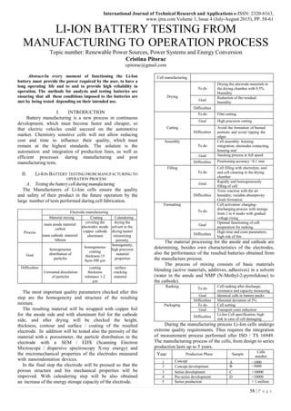
- 1. International Journal of Technical Research and Applications e-ISSN: 2320-8163, www.ijtra.com Volume 3, Issue 4 (July-August 2015), PP. 58-61 58 | P a g e LI-ION BATTERY TESTING FROM MANUFACTURING TO OPERATION PROCESS Topic number: Renewable Power Sources, Power Systems and Energy Conversion Cristina Pitorac cpitorac@gmail.com Abstract-In every moment of functioning the Li-Ion battery must provide the power required by the user, to have a long operating life and to and to provide high reliability in operation. The methods for analysis and testing batteries are ensuring that all these conditions imposed to the batteries are met by being tested depending on their intended use. I. INTRODUCTION Battery manufacturing is a new process in continuous development, which must become faster and cheaper, so that electric vehicles could succeed on the automotive market. Chemistry sensitive cells will not allow reducing cost and time to influence their quality, which must remain at the highest standards. The solution is the automation and integration of production lines, as well as efficient processes during manufacturing and post manufacturing tests. II. LI-ION BATTERY TESTING FROM MANUFACTURING TO OPERATION PROCESS A. Testing thebatterycellduring manufacturing The Manufacturers of Li-Ion cells ensure the quality and safety of their product in the future operation by the large number of tests performed during cell fabrication. Electrode manufacturing Material mixing Coating Calendering Process main anode material: carbon main cathode material: lithium covering the electrodes anode copper cathode aluminum drying the solvent in the drying tunnel minimizing porosity Goal homogeneous distribution of particles homogeneous coating thickness:15 0µm-300 µm homogeneity, high precision material properties Difficulties Unwanted dissolution of particles coating thickness tolerance 1-2 µm surface cracking material The most important quality parameters checked after this step are the homogeneity and structure of the resulting mixture. The resulting material will be wrapped with copper foil for the anode side and with aluminum foil for the cathode side, and after drying will be checked the height, thickness, contour and surface / coating of the resulted electrode. In addition will be tested also the porosity of the material with a porosimeter, the particle distribution in the electrode with a SEM / EDX (Scanning Electron Microscope / dispersive spectroscopy X-ray energy) and the micromechanical properties of the electrodes measured with nanoindentation devices. In the final step the electrode will be pressed so that the porous structure and his mechanical properties will be improved. With calendering step will be also obtained an increase of the energy storage capacity of the electrode. Cell manufacturing Drying To do Drying the electrode materials in the drying chamber with 0.5% Humidity Goal Reduction of the residual humidity Difficulties Cutting To do Film cutting Goal High precision cutting Difficulties Avoid the formation of burned portions and avoid ripping the edges Assembly To do Cell assembly: housing integration, electrodes contacting, housing seal Goal Stacking process at full speed Difficulties Positioning accuracy ~0.1 mm Filling To do Cell filling with electrolyte, seal and cell cleaning in the drying chamber Goal Rapidly and homogeneously filling of cell Difficulties Toxic reaction with the air humidity, variable absorptivity Goals formation Formatting To do Cell activation: charging- discharging process with storage from 2 to 4 weeks with gradual voltage rising Goal Optimal functioning of cell: preparation for ranking Difficulties High time and costs parameters; high risk of fire The material processing for the anode and cathode are determining, besides own characteristics of the electrodes, also the performance of the resulted batteries obtained from the manufacture process. The process of mixing consists of basic materials blending (active materials, additives, adhesives) in a solvent (water in the anode and NMP (N-Methyl-2-pyrrolidone) to the cathode). Ranking To do Cell ranking after discharge, resistance and capacity measuring Goal Identical cells in battery packs Difficulties Maximal deviation of 5% Packaging To do Cell sorting Goal Transport costs reduction Difficulties Li-Ion Cell specification, high risk in case of cell damaging During the manufacturing process Li-Ion cells undergo extreme quality requirements. Thus requires the integration of measurement process performed after ISO / TS 16949. The manufacturing process of the cells, from design to series production lasts up to 5 years. Year Production Phase Sample Cells number 1 Concept A ~1000 2 Concept development B ~5000 3 Series development C >10000 4 Pre-series development D >10000 5 Series production > 1 million
- 2. International Journal of Technical Research and Applications e-ISSN: 2320-8163, www.ijtra.com Volume 3, Issue 4 (July-August 2015), PP. 58-61 59 | P a g e The necessary data for production of the battery cells, such as: specifications, tolerances, process parameters, reactions plan, test methods, etc. are included in the control plan of the manufacturing process. Control plan exists for each component (anode, cathode, and separator). Each fabricated cell has a history that can be traced with the help of an identification number during the manufacturing process. The production of battery cells is an extremely difficult process that requires a large number of quality measurements. For example in the production of cathodes are described 70 measurements and 25 tests that will be made during the manufacturing process. The difficulty consists in that augmented cell tests may be performed only at the end of the manufacturing process. For a correct product development during the manufacturing process of the electrode is essential, in addition to quality control the implementation of characterization methods. The quality controls ensures the reproduction of the manufacturing process and minimize the number of rejects cells. The production machines/processes and process parameters must be correlated with the intermediate and final product parameters and also with the operating parameters of the resulted electrochemical battery. The test results of mechanical, electrical and electrochemical parameters characterization of electrodes are showing the correlation between machines / processes of production and operating characteristics of resulted cell. Tests Material mixing Suspension Phase electrical conductivity flow ability adsorption BET isotherm X-ray refractometry spectroscopy Powder dispersion stability Phase rheology particle size distribution mass concentration energy and surface tension Coating Electrode phase Mechanical: Adhesion Nanoindentation Structure: Porosimetry Computed tomography Optical: SEM EDX Electrical: AFM conductivity (atomic force microscope) Current transit conductivity in 4 points Electrochemistry: Tests of strength and long life impedance spectroscopy Process Measurements: Coating thickness Karl Fischer titration method TGA Thermogravimetric analysis Ultrasound scan Calendering Micro- and nanostructure of the electrodes determine the kinetics of transport of ions and electrons in the cell, the key to maximizing the energy density and power of the battery. It is necessary to adjust these structures depending on the type of vehicle in that will be implemented the resulted battery (EV, PHEV and HEV). Power density is determined of ions and electrons transport. The coating thickness and the irreversible capacity loss will determine the energy density. The temperature density determines the battery life time. Putting into operation of a power cell is recommended to be done with gradual increase of power, especially after storage for several months. During formatting, the cell will be "activated" and subject to a series of tests, including OCV test, after which it will accumulate certain quality and operating parameters with which will decide if the cell will be or will be not included in the successive steps of the battery manufacturing. The cell formatting includes: Charge discharge cycle Altering EOL Test Ranking Storage tests Loading and unloading processes of the cells change local concentrations inside cells. Thus, loss of voltage during these processes is also dependent on the range-concentration inside the cell battery, giving importance to characterize voltage depending on the time t and the applied current I. The higher the current, the higher the voltage loss and lesser measured final capacity. Formatting / aging / testing and correct diagnosis are quality factors that directly influence the production cost reduction, safety and lifetime of the battery cell. Sources of error are mainly: - Side reactions - Water - Homogeneity - Self discharge - Short circuit - Inserts of Li A testing scenario could be: - 1st altering phase 28h/25 grdC - Pre-charging - 2nd altering phase 24h/25 grdC - 1st ranking - 3rd altering phase 15 days/ 25 grdC - 2nd ranking - Final audit - Storage test B. Cell testing after manufacturing The problem of testing cells after the process of production is that it is sealed, not allowing the application of sensors inside it. Technically possible external measurements temperature (T), voltage (U) and current (I) are easy to perform and provides information, following the application of calculation formulas, about the power, energy, capacity and operational status of the SOH of the cell. It can also carry out measurements, such as post-mortem microscopy, ion chromatography, porosimetry. A stationary classical analysis is to define the curve dependency toward voltage and cell capacity. This analysis is used to determine the maximum capacity of the cell
- 3. International Journal of Technical Research and Applications e-ISSN: 2320-8163, www.ijtra.com Volume 3, Issue 4 (July-August 2015), PP. 58-61 60 | P a g e depending on the current I and analysis of capacity loss during aging, resulting in calculation of SOH. Battery cells will be subject to: Thermal performance tests - shows the influence of ambient temperature on cell performance tested. Capacity tests are generally power test carried out at temperatures between -30 ° C and 50 ° C. Cold start tests - check tested cell power at low temperatures (-30° C) Capacity Tests - check the ability of cells to discharge at different current rates Pulse power tests - determine the dynamic response of the cell under test by applying pulses of loading and unloading in order to determine its strength and available energy Self-discharge tests - characterized the capacity loss of lithium based cells without being used. Li-Ion cells have a longer life of 10 years with a self- discharge rate of 2-3% per month. Energy efficiency tests - determine the energy capacity of the battery by applying certain specific energy profiles. Cyclic life tests- demonstrates that the cell may be subject to different paternal and levels of energy use of available capacity. Calendar life Tests - demonstrates the degradation of a cell for a certain length of time with a minimum use. Reference performance tests - set of tests that are performed periodically over the life of the cell to describe the state and its degradation during testing. For operational safety reasons, in addition to the above described tests, will be effectuated a series of abusive tests describing the risk situation such as: short-circuit, overload, accident, overheating and so on. C. Li-Ion battery pack testing The analyzed problems in the case of batteries are related to power, energy, borders of functioning and response to external system of the battery. Based on the basic measurements (U, I, T) will be derived the values for the characteristic parameters such as SOC, SOH, energy density, power density, capacity etc. Because the battery cooling will be effected by means of a Tub, will be very important and writing papers temperatures. Because the battery cooling will be effectuated trough an exterior system it will be very important to determine the temperature map. Batteries and battery module(s) shall be subject of the following tests: - Impedance spectroscopy tests - special tests that verify the thermal behavior of the controller modules of the battery - Thermal tests - check the battery behavior at various temperatures (-30 ° C <->52 ° C) the performance of lithium based cells decreases with temperature - Level combined testing of cell life - combines the cyclization tests with the tests of storage at high temperatures with the objective to validate the behavior of the battery under stress conditions - Vibration tests - vibration tests on x, y and z axes help to identify the weaknesses points of the battery construction. Vibration tests can be conducted also in climatic chambers where temperature and humidity can be strictly controlled - Operating tests - tests to validate the operation of the battery in normal conditions and extremes temperature. In the case of battery system (battery + BMS) will be checked the battery monitoring and control of the battery trough BMS. Although each cell is different from the other, the system works as a single unit, the cells are simultaneously performing the same processes. In every moment is important to identify the cell with the farthest behavior from the others (the "bad" cell). The protocols of testing the battery performance are developed in function of type of vehicle in which will be implemented. Test procedures are generally adopted by existing standards (FreedomCar Battery Testing, Battery Testing Eucar etc.). Phase Tests BMS developing HIL Testing BMS verification and validation Battery Pack developing Battery pack verification and validation Battery module fabrication Module cyclisation Module balancing Battery pack fabrication EOL testing Battery pack cyclisation Battery pack testing with different driving cycles Battery pack balancing HIL Tests (Hardware in the Loop) allow, in the design phase, the BMS testing under real operating conditions, so it can be checked and validated. HIL tests are implying the simulation of physical input quantities and digital connections with external battery pack and the monitoring system reactions during operation compared with project requirements. Testing during design phase involves trying its battery pack under extreme temperature cycles of charging and discharging, vibration, humidity, thermal shock, or various combinations thereof. Such attempts include a series of performance tests before and after the application of one or more stressors on the battery pack. Tests carried out during manufacture of battery modules are dedicated to check the connections between the cells of battery with the main points of interest their resistance during charging and discharging cycles and their behavior at high temperatures. Besides these tests will be also checked the cooling system of the module, the sensors and the cell balancing. Testing the complete package of the battery (battery pack + BMS) is made before final assembly point (End of Line). At this point the tests ensure the smooth functioning of battery system and its components and subsystems in use. These tests involve checking the safety systems and the operation and communication with BMS. After completing the tests of functionality, the complete package of batteries is subjected to charge discharge cyclization and different tests with different driving profiles in order to validate its functionality in real conditions on the electric/hybrid vehicle. Complete battery packs are also subject to routine cell balancing in order to bring each cell voltage to a nominal value or to set the state of charge SOC to an appropriate level for the delivery and storage. III. TESTING AUTOMATION An automatic test field will ensure the money save and the time loss by programming and care of the test and test
- 4. International Journal of Technical Research and Applications e-ISSN: 2320-8163, www.ijtra.com Volume 3, Issue 4 (July-August 2015), PP. 58-61 61 | P a g e field. The system which need to be automatized is the one formed from test bench, test object and the test procedure. The test field is formed from one or more such systems. To have a successfully automatized test field must be identified the fall in which a new test has to be implemented. The new test other will meet all three characteristics of the test field system other will meet two of all three characteristic other will meet only one of all three characteristic other will meet none of all three characteristic, moment in which is needed to be identified from which of the three characteristic of the test field system is the new test closer. The test field is formed on one hand of the software, and the other hand of the hardware. The hardware side consist of test benches, measurement technique and test object. The software side consist of the database of the test field. The database will contain the test bench data, the test procedures and the characteristic data of the test objects. According to the new test the database will be richer with the new data which must be added in order to fulfill the new needed test. The test procedure data will contain all the test programmed in the database. The test bench data order will contain all the necessary data for the operation of the test bench (cooling, safety, etc.). The test object data will contain the characteristic data of the test object. This data will also include the software data of the tested object (BMS, CAN communication), test object data (manufacturer, weight, power, etc.) and the test object type (nominal and limit values) Working with links to the original information will allow in the field database to define only one time one new information. This structure helps to shorten the time needed programming test and automate them. One schematic hardware structure of a test field is shown above. These structure consist of a test bench. a user PC, and test bench control PC and an energy system. The energy systems is the heart of the structure because it controls the charge and discharge of the battery and it contains also an inverter due the operation will be dynamic and stabile. The communication between User PC and PC Control is type DDE (Dynamic Data Exchange). PC Control has installed the real time operation system QNX. It contains also a programmable controller SPS which is responsible for ensuring operational safety and receiving signals sent by the sensors and also actuators driving. The test results are also saved on this computer. The user PC with windows system will be used to programming the test procedures. IV. CONCLUSION Testing batteries is a process that requires time and money. Improving the process of testing can be performed after an international collaboration between testing centers. The collaboration could result in standardizing the test and analysis of results, which would directly influence the developmental market electric vehicles. Standardized testing procedures are crucial in comparing different technologies. REFERENCES [1]. Dipl.-Ing. Markus Plöger, Dr.-Ing. Hagen Haupt, Dipl.- Ing. Jörg Bracker, dSPACE GmbH, Germany ‘HIL Testing of Battery Management Systems’ Automobil Elektronik 10/2011 [2]. DHAMEJA, S. ‘Electric Vehicle Battery Systems’, 2001 [3]. USABC, ‘Electric vehicle battery test procedures manual’, 1996 Seminar, ‘, 2014 [4]. FreedomCar, ‘FreedomCAR Battery Test Manual’, 2003 [5]. US Department of energy, ‘Battery Test Manual for Plug- [6]. In Hybrid Electric Vehicles’, 2008 [7]. www.batteryuniversity.com