International Journal of Engineering Research and Development
•
1 gefällt mir•193 views

Electrical, Electronics and Computer Engineering, Information Engineering and Technology, Mechanical, Industrial and Manufacturing Engineering, Automation and Mechatronics Engineering, Material and Chemical Engineering, Civil and Architecture Engineering, Biotechnology and Bio Engineering, Environmental Engineering, Petroleum and Mining Engineering, Marine and Agriculture engineering, Aerospace Engineering.

Empfohlen
Weitere ähnliche Inhalte
Was ist angesagt?
Was ist angesagt? (20)
Andere mochten auch
Andere mochten auch (16)
Ähnlich wie International Journal of Engineering Research and Development
Ähnlich wie International Journal of Engineering Research and Development (20)
Mehr von IJERD Editor
Mehr von IJERD Editor (20)
Kürzlich hochgeladen
Kürzlich hochgeladen (20)
International Journal of Engineering Research and Development
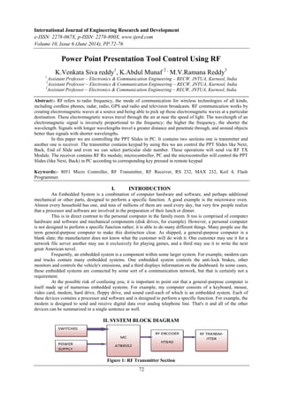
- 1. International Journal of Engineering Research and Development e-ISSN: 2278-067X, p-ISSN: 2278-800X, www.ijerd.com Volume 10, Issue 6 (June 2014), PP.72-76 72 Power Point Presentation Tool Control Using RF K.Venkata Siva reddy1 , K.Abdul Munaf 2 , M.V.Ramana Reddy3 1 Assistant Professor – Electronics & Communication Engineering – RECW, JNTUA, Kurnool, India 2 Assistant Professor – Electronics & Communication Engineering – RECW, JNTUA, Kurnool, India 3 Assistant Professor – Electronics & Communication Engineering – RECW, JNTUA, Kurnool, India Abstract:- RF refers to radio frequency, the mode of communication for wireless technologies of all kinds, including cordless phones, radar, radio, GPS and radio and television broadcasts. RF communication works by creating electromagnetic waves at a source and being able to pick up those electromagnetic waves at a particular destination. These electromagnetic waves travel through the air at near the speed of light. The wavelength of an electromagnetic signal is inversely proportional to the frequency; the higher the frequency, the shorter the wavelength. Signals with longer wavelengths travel a greater distance and penetrate through, and around objects better than signals with shorter wavelengths. In this paper we are controlling the PPT Slides in PC. It contains two sections one is transmitter and another one is receiver. The transmitter contains keypad by using this we are control the PPT Slides like Next, Back, End of Slide and even we can select particular slide number. These operations will send via RF TX Module. The receiver contains RF Rx module, microcontroller, PC and the microcontroller will control the PPT Slides (like Next, Back) in PC according to corresponding key pressed in remote keypad Keywords:- 8051 Micro Controller, RF Transmitter, RF Receiver, RS 232, MAX 232, Keil 4, Flash Programmer. I. INTRODUCTION An Embedded System is a combination of computer hardware and software, and perhaps additional mechanical or other parts, designed to perform a specific function. A good example is the microwave oven. Almost every household has one, and tens of millions of them are used every day, but very few people realize that a processor and software are involved in the preparation of their lunch or dinner. This is in direct contrast to the personal computer in the family room. It too is comprised of computer hardware and software and mechanical components (disk drives, for example). However, a personal computer is not designed to perform a specific function rather; it is able to do many different things. Many people use the term general-purpose computer to make this distinction clear. As shipped, a general-purpose computer is a blank slate; the manufacturer does not know what the customer will do wish it. One customer may use it for a network file server another may use it exclusively for playing games, and a third may use it to write the next great American novel. Frequently, an embedded system is a component within some larger system. For example, modern cars and trucks contain many embedded systems. One embedded system controls the anti-lock brakes, other monitors and controls the vehicle's emissions, and a third displays information on the dashboard. In some cases, these embedded systems are connected by some sort of a communication network, but that is certainly not a requirement. At the possible risk of confusing you, it is important to point out that a general-purpose computer is itself made up of numerous embedded systems. For example, my computer consists of a keyboard, mouse, video card, modem, hard drive, floppy drive, and sound card-each of which is an embedded system. Each of these devices contains a processor and software and is designed to perform a specific function. For example, the modem is designed to send and receive digital data over analog telephone line. That's it and all of the other devices can be summarized in a single sentence as well. II. SYSTEM BLOCK DIAGRAM Figure 1: RF Transmitter Section
- 2. Power Point Presentation Tool Control Using RF 73 Figure 2: RF Receiver Section The block diagram of power point presentation tool using RF contains RF transmitter and RF receiver. Figure 1 shows block diagram of RF transmitter in which switches are connected to AT89S52 by which we give the inputs like slide 1, slide2, start of slide, end of slide, etc. to AT89S52. Transmitter section transmits these commands to receiver section. At receiver section, RF receiver receives the commands and send them to receiver controller AT89S52. This controller will change the slides in PC according to input commands. One MAX 232 is used in receiver section for voltage conversions. III. HARDWARE AND SOFTWARE DESIGN 3.1 RF Transmitter and Receiver RF refers to radio frequency, the mode of communication for wireless technologies of all kinds, including cordless phones, radar, ham radio, GPS, and radio and television broadcasts. RF waves are electromagnetic waves which propagate at the speed of light, or 186,000 miles per second (300,000 km/s). The frequencies of RF waves, however, are slower than those of visible light, making RF waves invisible to the human eye. The frequency of a wave is determined by its oscillations or cycles per second. One cycle is one hertz (Hz); 1,000 cycles is 1 kilohertz (KHz); 1 million cycles is 1 megahertz (MHz); and 1 billion cycles is 1 gigahertz (GHz). A station on the AM dial at 980, for example, broadcasts using a signal that oscillates 980,000 times per second, or has a frequency of 980 KHz. A station a little further down the dial at 710 broadcasts using a signal that oscillates 710,000 times a second, or has a frequency of 710 KHz. With a slice of the RF pie licensed to each broadcaster, the RF range can be neatly divided and utilized by multiple parties. Every device in the United States that uses RF waves must conform to the Federal Communications Commission's (FCC) regulations. A baby monitor, for example, must operate using the designated frequency of 49 MHz. Cordless phones and other devices have their own designated frequencies. When an RF current is supplied to an antenna, it gives rise to an electromagnetic field that propagates through space. This field is sometimes called an RF field.RF field has a wavelength that is inversely proportional to the frequency. In the atmosphere or in outer space, if f is the frequency in megahertz and s is the wavelength in meters, then s = 300/f. The frequency of an RF signal is inversely proportional to the wavelength of the EM field to which it corresponds. At 9 kHz, the free-space wavelength is approximately 33 kilometers (km) or 21 miles (mi). At the highest radio frequencies, the EM wavelengths measure approximately one millimeter (1 mm). Figure 3: RF Transmitter and Receiver
- 3. Power Point Presentation Tool Control Using RF 74 3.2 Ranges of RF The RF spectrum is divided into several ranges, or bands. Designation Abbreviation Frequencies Free-space Wavelengths Very Low Frequency VLF 9 kHz - 30 kHz 33 km - 10 km Low Frequency LF 30 kHz - 300 kHz 10 km - 1 km Medium Frequency MF 300 kHz - 3 MHz 1 km - 100 m High Frequency HF 3 MHz - 30 MHz 100 m - 10 m Very High Frequency VHF 30 MHz - 300 MHz 10 m - 1 m Ultra High Frequency UHF 300 MHz - 3 GHz 1 m - 100 mm Super High Frequency SHF 3 GHz - 30 GHz 100 mm - 10 mm Extremely High Frequency EHF 30 GHz - 300 GHz 10 mm - 1 mm Table 1 Ranges of RF In order that a steady radio signal or "radio carrier" can carry information it must be changed or modulated in one way so that the information can be conveyed from one place to another. There are very many ways in which a radio carrier can be modulated to carry a signal, each having its own advantages and disadvantages. There are three main ways in which a radio communications or RF signal can be modulated: Amplitude modulation Frequency modulation Phase modulation Each type of modulation has its own advantages and disadvantages, and accordingly the are all used in different radio communications applications. 3.3 RF Encoder Figure 4: RF Encoder HT12E is an encoder integrated circuit of 212 series of encoders. They are paired with 212 series of decoders for use in remote control system applications. It is mainly used in interfacing RF and infrared circuits. The chosen pair of encoder/decoder should have same number of addresses and data format. Simply put, HT12E converts the parallel inputs into serial output. It encodes the 12 bit parallel data into serial for transmission through an RF transmitter. These 12 bits are divided into 8 address bits and 4 data bits. HT12E has a transmission enable pin which is active low. When a trigger signal is received on TE pin, the programmed addresses/data are transmitted together with the header bits via an RF or an infrared transmission medium. HT12E begins a 4-word transmission cycle upon receipt of a transmission enable. This cycle is repeated as long as TE is kept low. As soon as TE returns to high, the encoder output completes its final cycle and then stops.
- 4. Power Point Presentation Tool Control Using RF 75 Computer 3.4 RF Decoder Figure 5: RF Decoder HT12D is a decoder integrated circuit that belongs to 212 series of decoders. This series of decoders are mainly used for remote control system applications, like burglar alarm, car door controller, security system etc. It is mainly provided to interface RF and infrared circuits. They are paired with 212 series of encoders. The chosen pair of encoder/decoder should have same number of addresses and data format. In simple terms, HT12D converts the serial input into parallel outputs. It decodes the serial addresses and data received by, say, an RF receiver, into parallel data and sends them to output data pins. The serial input data is compared with the local addresses three times continuously. The input data code is decoded when no error or unmatched codes are found. A valid transmission in indicated by a high signal at VT pin. HT12D is capable of decoding 12 bits, of which 8 are address bits and 4 are data bits. The data on 4 bit latch type output pins remain unchanged until new is received. IV. INTERFACING 4.1 PC INTERFACE WITH MICRO CONTROLLER Figure 6: PC interface with microcontroller In this project PC is interfaced with the microcontroller through RS232 interface. Since the voltage levels of the microcontroller are different with that of the PC we use a voltage converter or the line driver such as MAX232 to make them RS232 compatible. 4.2 Transmitting circuit with 8051 Figure 7: Complete schematic of Transmitter
- 5. Power Point Presentation Tool Control Using RF 76 The above figure is a complete schematic of RF transmitter. In this 4x4 keypad is connected to Port 1 of 8051. RF encoder is connected to port 0 of 8051 micro controller through pull up resistors. RF transmitter and antenna is connected to rf encoder. 4.3 Receiving circuit with 8051 Figure 8: Complete schematic of Receiver The above figure shows complete schematic of receiver. The receiver section will receive the commands send by the transmitter section. RF receiver is connected to port 0 of 8051 micro controller through pull up resistors. 8051 has one serial port to which PC is connected. One max 232 is connected between UART and 8051 micro controller for voltage conversion. The receiver micro controller controls the slides in the system according to commands y the RF receiver. V. CONCLUSION This Project was mainly exploring the important tool for many people who were exchanging knowledge especially proceeding power-point presentation as one auxiliary tool. The presentator most proper position should be between the audience and screen of power-point and if this location is far away the mouse or keyboard it becomes difficult to control PPT and also if he want go for particular slide using mouse or keyboard is long process, so this Project helps us to control the PPTs for going to our desire slide using RF remote from far distance, so that the user not need to go to the keyboard or mouse to change the ppt and could be controlled with RF remote. REFERENCES [1]. FUN , I.C (2007).The serial communication control design of RS 232 with visual basic. Wenkuei information and press ltd. Company. [2]. “The study on design speech control power point presentation tool” by kune-yao chen and paper number is 978-1-4244-6527-9/10-IEEE 2010 paper. [3]. The design of speech control power point presentation tool using ARM 7 by P.Vishnu Kumar and Dr.T.Jaya Chandra Prasad, IJCTT, Volume 3, issue4 ,2012. [4]. The 8051 Microcontroller and Embedded Systems Using Assembly and C Second Edition By Muhammad Ali Mazidi Janice Gillispie Mazidi [5]. Huang, Y.F. Huang, G.H. Hu. Z.Y. (2005). Development of an expert system for tackling the public's perception to climate-change impacts on petroleum industry. Expert Systems with Applications, Volume 29, Issue 4, 817-829. [6]. Lin, S.C. (2003). Communication protocol of message package of BT Net. Master thesis, Electronic Engineering Department of Fen-Kai University. [7]. Fan, I. C. (2007). Visual basic and RS232 serial communication port. Wen-Qwei Information Ltd. Corp. [8]. www.atmel.com [9]. www.amtech.com